METU – ME 308 Machine Elements II – Spring 2005
1
Prepared by: Erge Koray
Room: B-316 Phone: 5264
E-mail: erge@metu.edu.tr Date: 10/03/2005
ME 308 – MACHINE ELEMENTS II
TUTORIAL 1
“LUBRICATION & JOURNAL BEARINGS”
NOTE:
• The sign (*) denotes “ME 308 Notes to be used in examinations” or
“ Shigley Metric Edition”.
• The sign (**) denotes “Shigley 5
th
Edition”
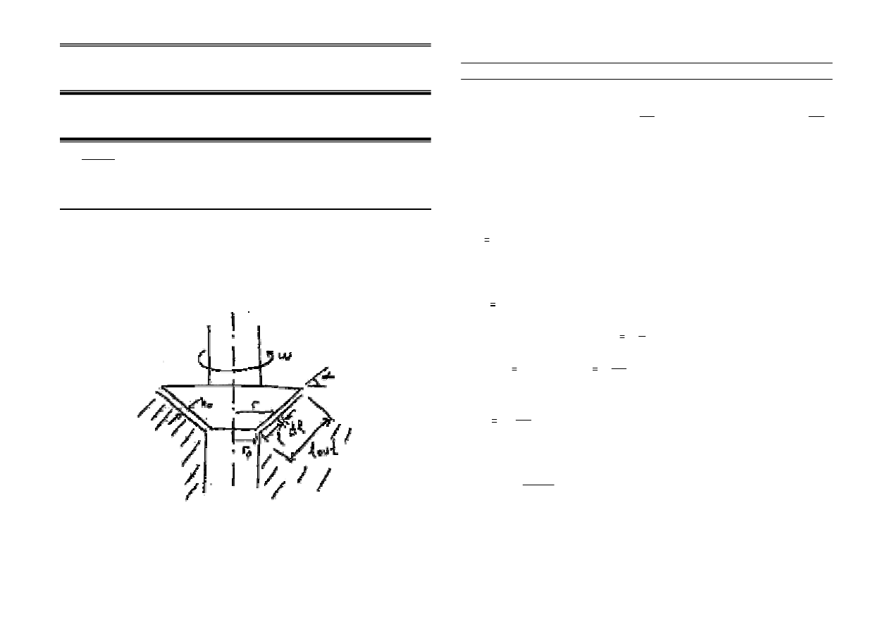
1)
A conical bearing with a facial length of lout=150 mm at a cone angle of
400 rotates at a constant angular speed of
ω=50 rad/s. It rests against a
conical surface. Determine the torque T applied on the bearing if the minimum
film thickness is h=0.025 mm. The gap in between is completely filled with
SAE 20. Operating temperature is 800 C. r
0
= 40 mm.
SOLUTION
rad
s
α
40
π
180
⋅
:=
h
0.025 10
3
−
⋅
:=
r0 40 10
3
−
⋅
:=
m
ω
50
:=
m
lout 0.15
:=
m
r
r0 l cos α
( )
+
:=
⋅
l
Using Figure 12-10 *
µ
9 10
3
−
⋅
:=
Pa s
⋅
The torque caused by shear forces can be formulated for infinitely small element as
follows.
dT
r d
⋅ F
The elementary shear force on a radial segment dr can be calculated by the shear
stress acting on the element.
dA = 2πr dl
dF
τ dA
⋅
where
τ µ
u
h
⋅
Shear stress is equal to
τ µ
ω r
⋅
h
⋅
and
u
ω r
⋅
so
combining these equations
dT
µ
ω r
⋅
h
⋅
2
π
⋅ r
⋅ dl
⋅
(
)
⋅
⎡⎢
⎣
⎤⎥
⎦
r
⋅
then
T
0
lout
l
2
π µ
⋅ ω
⋅
h
r0 l cos α
( )
⋅
+
(
)
3
⋅
⌠
⎮
⎮
⌡
d
:=
T
21.158
=
N m
⋅

METU – ME 308 Machine Elements II – Spring 2005
2
2)
A 100-mm diameter full journal bearing supports a radial load of 4500
N. The shaft works at 500 rpm and the bearing is 25 mm long. Assuming
a permissible minimum film thickness of 0.01 mm and H8/f7 fit for the
bearing bore, determine:
(a) The dynamic viscosity µ of a suitable oil,
(b) The coefficient of friction, f,
(c) The heat generated, H
g
,
(d) The total amount of oil volume flow rate, Q,
(e) The amount of side leakage, Q
s
, (the amount of oil to be supplied to
the bearing),
(f) The temperature rise of the oil, ∆T, flowing through the bearing.
SOLUTION
By using Tables A.11 and E.12** or any available tolerance table:
H8: (100 + 0 < D < 100 + 0.054) and f7: (100 – 0.036 > D > 100 – 0.071)
The question will be solved both for the maximum and minimum clearance
values which are limited by the desired fit H8/f7.
For maximum clearance:
(a) A maximum diametral clearance of C = 0.125 mm is achieved along the
diameters. And therefore, the maximum radial clearance will be c = 0.125 / 2 =
0.0625 mm.
From Figure 12.13* or Figure 12.14**, the value of the Sommerfeld number,
S, can be obtained for (h
o
/ c) = 0.01 / 0.0625 = 0.16 and (l / d) = 25/100=1/4:
S = 0.18
Also,
4500
1800000
*
0.1 0.025
W
P
d l
=
=
=
⋅
Pa
Then by using the bearing characteristic number formula:
2
2
50
(500 / 60)
0.18
0.0625
1800000
r
N
S
c
P
µ
µ
⎛ ⎞
⎛
⎞
⎜ ⎟
⎜
⎟
⎝ ⎠
⎝
⎠
=
=
=
from where µ is obtained as:
µ ≈ 0.06075 Pa.s ≈ 60.75 mPa.s
(b) From Figure 12.16*, 12.17**, for S = 0.18 and (l/d) = 1/4:
(
c
r ) f = 6.75 → f = 6.75*(0.0625 / 50) = 0.00844
(c) Heat generated is:
500
(
)(
) (0.00844 4500)(
0.1
)
60
60
g
N
H
T
F V
f W
d
ω
π
π
= ⋅ = ⋅ =
⋅
⋅ ⋅
=
⋅
⋅
⋅
H
g
≈ 99.43 W
(d) The total amount of oil volume flow rate, Q, is found by using Figure
12.17*, 12.18**. For S = 0.18 and (l/d) = 1/4:
3
5.75
(5.75)(0.05)(0.0625 10 )(500 / 60)(0.025)
Q
Q
rcNl
−
=
⇒
=
⋅
Q = 3.74·10
-6
m
3
/s
(e) The amount of side leakage, Q
s
, (the amount of oil to be supplied to the
bearing) can be obtained from Figure 12.18*, 12.19**. For S = 0.18 and (l/d) =
1/4:
Q
s
/Q = 0.91 → Q
s
= (0.91)(3.74·10
-6
) = 3.403·10
-6
m
3
/s
(g) The temperature rise of the oil, ∆T, flowing through the bearing can
be found by using Figure 12.12*. For S = 0.18 and (l/d) = 1/4:
(var)
18
H
C
T
T
P
γ
∆
=
≈
Taking γ = 860 kg/m
3
and C
H
= 1760 j/kg˚C:
∆T = 21.4 ˚C
For minimum clearance:

METU – ME 308 Machine Elements II – Spring 2005
3
(a) A minimum clearance of C = 0.036 mm is achieved along the diameters.
And therefore, the minimum radial clearance will be c = 0.036 / 2 = 0.018 mm.
From Figure 12.13* or Figure 12.14**, the value of the Sommerfeld number,
S, can be obtained for (h
o
/ c) = 0.01 / 0.018 = 0.555 and (l / d) = 1/4:
S = 2.2
Then by using the bearing characteristic number formula:
2
2
50
(500 / 60)
2.2
0.018
1800000
r
N
S
c
P
µ
µ
⎛ ⎞
⎛
⎞
⎜ ⎟
⎜
⎟
⎝ ⎠
⎝
⎠
=
=
=
from where µ is obtained as:
µ ≈ 0.0616 Pa.s ≈ 61.6 mPa.s
(b) From Figure 12.16*, 12.17**, for S = 2.2 and (l/d) = 1/4:
(
c
r ) f = 50 → f = 50(0.018 / 50) = 0.018
(c) Heat generated is:
500
(
)(
) (0.018 4500)(
0.1
)
60
60
g
N
H
T
F V
f W
d
ω
π
π
= ⋅ = ⋅ =
⋅
⋅ ⋅
=
⋅
⋅
⋅
H
g
≈ 212.1 W
(d) The total amount of oil volume flow rate, Q, is found by using Figure
12.17*, 12.18**. For S = 2.2 and (l/d) = 1/4:
3
4.55
(4.55)(0.05)(0.018 10 )(500 / 60)(0.025)
Q
Q
rcNl
−
=
⇒
=
⋅
Q = 8.53·10
-7
m
3
/s
(e) The amount of side leakage, Q
s
, (the amount of oil to be supplied to the
bearing) can be obtained from Figure 12.18*, 12.19**. For S = 2.2 and (l/d) =
1/4:
Q
s
/ Q = 0.62 → Q
s
= (0.62)(8.53·10
-7
) = 5.29·10
-7
m
3
/s
(h) The temperature rise of the oil, ∆T, flowing through the bearing can
be found by using Figure 12.12*. For S = 2.2 and (l/d) = 1/4:
(var)
160
H
C
T
T
P
γ
∆
=
≈
Taking γ = 860 kg/m
3
and C
H
= 1760 j/kg˚C:
∆T = 190 ˚C
Therefore, according to the clearance range, the results are obtained as
follows:
c
max
c
min
H
g
≈ 99.43 W
≈ 212.1 W
Q
3.74·10
-6
m
3
/s 8.53
10
-7
m
3
/s
Q
s
3.403·10
-6
m
3
/s 5.29·10
-7
m
3
/s
∆T
21.4 ˚C
190 ˚C
3)
A journal bearing supports a shaft rotating at 2500 rpm with a load of 5 kN.
The bearing is supplied with SAE 10 oil at an inlet temperature of 40˚C. The
shaft has 45 mm diameter. Design the journal bearing.
SOLUTION
In order to design the journal bearing; the type of the bearing (pressure-fed or
non-pressure-fed), length l, and a standard fit should be determined.
For the sake of maintenance, a non-pressure-fed bearing may be selected as
a first choice. As l / d ratio gets larger, pressure in the oil and side leakage
decreases, and consequently, minimum film thickness increases. In order to
enhance the probability of the non-pressure-fed bearing design, l / d = 1
should be preferred instead of ½ or ¼ ratios.

METU – ME 308 Machine Elements II – Spring 2005
4
Since the most critical parameters in a journal bearing are minimum film
thickness (h
o
) and maximum oil temperature (T
max
), (h
o
vs. c) and (T
max
vs. c)
graphs are to be plotted in order to determine the optimum range for
clearance, c. As soon as a clearance range is determined, a standard fit can
easily be selected for the bearing and shaft.
Two procedures can be employed to obtain a (h
o
vs. c) and (T
max
vs. c)
graphs:
1
ST
PROCEDURE:
¾
Take a ‘c’ value.
¾
Assume
∆T → Calculate T
av
and T
max
→ Find µ → Calculate S →
Find h
o
→ Find T
(var)
→ Calculate ∆T.
¾
Continue the iterations until assumed ∆T and calculated ∆T are in
agreement.
¾
As soon as ∆T’s are in agreement, plot h
o
and T
max
vs c.
2
ND
PROCEDURE:
¾
Take
a
∆T value, calculate T
max
and find µ.
¾
Calculate
T
(var)
from the formula
P
C
T
T
H
(var)
⋅
⋅
=
γ
∆
¾
Find S from Figure 12.12* (In the 6
th
Ed. the relation is given as an
equation) using T
(var)
and l/d ratio.
¾
Calculate
c
from
P
N
c
r
S
µ
2
⎟
⎠
⎞
⎜
⎝
⎛
=
¾
Find
h
o
/c from Fig 12.13*, 12.14** and calculate h
o
.
¾
Plot
h
o
and T
max
vs c.
In order to demonstrate the procedures, each procedure will be explained by a
sample calculation:
SAMPLE CALCULATION USING PROCEDURE 1:
Take c = 20 µm.
Assume ∆T = 30˚C
1
30
40
55
2
2
av
T
T
T
C
Using T
av
for SAE 10 oil from Figure 12.10*, 12.12**; µ = 16 mPa.s
2
2
22.5
0.016 (2500 / 60)
0.342
0.020
2469000
r
N
S
c
P
µ
⋅
⎛ ⎞
⎛
⎞
=
=
=
⎜ ⎟
⎜
⎟
⎝ ⎠
⎝
⎠
By using S at Fig. 12.12*, T
(var)
= 30.
(var)
30 2469000
48.9
860 1760
H
T
P
T
C
C
γ
⋅
∆ =
=
=
⋅
D
→ Assumption failed.
By repeating the steps in the procedure above:
Assume ∆T = 40˚C → Calculated ∆T ≈ 40˚C → Assumption satisfied
For the verified value of S = 0.28 at ∆T = 40˚C from Figure 12.13*, 12.14**;
h
o
/c = 0.6, then finally:
h
o
= (20)(0.6) = 12 µm.
SAMPLE CALCULATION USING PROCEDURE 2:
The same result can be obtained by using the second procedure:
Assume ∆T = 40˚C.
(var)
24.52
H
C
T
T
P
γ
∆
=
=
From Figure 12.12*, by using T
(var)
and l / d = 1:
S = 0.28
Then, from the equation of S, c is calculated:
2
2
22.5
0.013 (2500 / 60)
0.27
20
2469000
r
N
S
c
m
c
P
c
µ
µ
⋅
⎛ ⎞
⎛
⎞
=
=
=
⇒ =
⎜ ⎟
⎜
⎟
⎝ ⎠
⎝
⎠
∆
= +
=
+
=
D
From Figure 12.13*, 12.14**; h
o
/c = 0.6, then finally:
METU – ME 308 Machine Elements II – Spring 2005
5
h
o
= (20)(0.6) = 12 µm.
By using either procedure 1 or procedure 2, the following table is formed:
c (µm)
∆T (˚C)
T
max
(˚C)
µ(mPa.s)
S
h
o
(µm)
ε
7
108
148
4.7
0.82
5.74
0.18
10
80
120
7
0.6
7.8
0.22
20
40
80
13
0.28
12
0.4
25
32
72
15.4
0.21
13
0.462
28
29
69
16.2
0.177
13.72
0.51
30
27
67
17
0.16
14.1
0.53
32
26
66
17.9
0.149
14.2
0.555
34
24
64
18
0.133
14.1
0.585
36
22
60
19.4
0.132
14.04
0.61
38
21
61
19
0.11
13.6
0.64
The recommendations and requirements for a non-pressure-fed bearing are
as follows:
¾
h
o
> surface roughness
¾
0.9
>
ε > 0.5 (ε is the eccentricity ratio, ε = 1 - (h
o
/c))
¾
h
o
> 8-10 µm
As seen from the Table above and h
o
and T
max
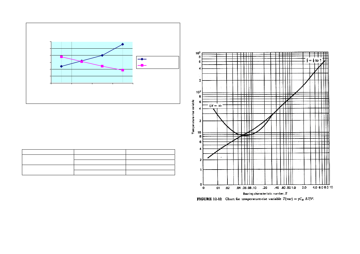
vs c graph below, a non-
pressure-fed bearing can be used. It will be better to select the clearance
range slightly to the left of the peak, which can be seen in the h
o
-c plot, as
future wear will move the operation region towards the peak, namely to the
right-hand side.
Note that, h
o
values are 10 times exaggerated for the sake of a clearer plot.
As a result c
max
< 32 µm.
For bearing tolerances, Basic Hole System is used. Note that the calculated c
values are the radial clearances between the bearing and the shaft (c = R – r).
But standard tolerances are defined over diameters (C = D – d). Then, C = 2c.
And, since a clearance fit will be employed, tolerance letter codes c, d, f, g
should be used for the shaft. By using Tables A.11 and E.12**, or any
available tolerance table
ho and Tmax vs c
0
20
40
60
80
100
120
140
160
5
10
15
20
25
30
35
40
c
T
m
ax, 10*
h
o
Tmax
ho
For bearing with a nominal dia. = 45
mm
For shaft with a nominal dia. = 45 mm
H6: (45 + 0 < D < 45 + 0.016)
H7: (45 + 0 < D < 45 + 0.025)
H8: (45 + 0 < D < 45 + 0.039)
H9: (45 + 0 < D < 45 + 0.062)
f5: (45 – 0.025 > D > 45 – 0.036)
f6: (45 – 0.025 > D > 45 – 0.041)
f7: (45 – 0.025 > D > 45 – 0.050)
g6: (45 – 0.009 > D > 45 – 0.025)
C
max
(µm)
C
min
(µm)
c
max
(µm)
c
min
(µm)
H6/g6
41
9
20.5
4.5
H7/f5
61
25
30.5
12.5
H7/f7
75
25
37.5
12.5
H8/g6
64
9
32
4.5
…..
…..
…..
…..
…..
Some of the combinations are taken into account as follows:
¾
H6/g6 and H8/g6 are not appropriate because of high T
max
and
unacceptable minimum film thickness, h
o
.
¾
H7/f7 is not appropriate because of c
max
, which lies beyond the peak
of the h
o
-c graph.
H7/f5 can be accepted as c
max
lies just before the peak region. This choice
seems to be the best fit among the other alternatives
METU – ME 308 Machine Elements II – Spring 2005
6
4)
A porous bronze full journal bearing supports a load of 4 kN at 200 rpm.
SAE 20 oil is used. The radial clearance is 40 µm, and the diameter and the
length of the bearing are 30 mm. Determine the bearing temperature when the
ambient temperature is 20˚C.
SOLUTION
If the lubrication condition is full-film lubrication, the working temperature can
be estimated with the iterative methods as explained in the previous
problems. On the other hand, if the lubrication condition is boundary
lubrication, another method should be employed. So, the lubrication type must
be determined. Boundary lubrication is the case if h
o
is comparable with
surface roughness or h
o
/c < 0.05.
Then:
P = W /(dl) = 4000/(0.03)
2
= 4.4 MPa
Assuming T
av
= 40˚C, from Figure 12.10*, 12.12** µ = 50 mPa.s
0053
0
4400000
60
200
050
0
040
0
15
2
2
.
)
/
(
.
.
P
N
c
r
S
=
⋅
⎟
⎠
⎞
⎜
⎝
⎛
=
⎟
⎠
⎞
⎜
⎝
⎛
=
µ
and l/d = 1
From Figure 12.13*, 12.14**:
h
o
/c = 0.03, since c = 40 µm; h
o
= 0.03(40) = 1.2 µm.
T
av
(˚C)
µ(mPa.s)
S
h
o
/c
ε
h
o
(µm)
40
50
0.0053
0.03
0.97
1.2
45
36
0.0038
0.02
0.98
0.8
50
28
0.0030
0.015
0.985
0.6
From this table, since ε ≈ 1.0 due to rubbing, we can conclude that boundary
lubrication is the case. Then, from Table 12.5*,12.6**
Max. Load
31 MPa
Max. Temperature
65 ˚C
Max. Speed
7.5 m/s
Max. P·V
1750 kPa.m/s
The values in the table should be checked and should not be exceeded.
Check for V:
V = ω·r = πdN/60 = π(200)(0.03)/60 = 0.314 m/s < 7.5 m/s ……… OK
Check for P:
4.4 MPa < 31 MPa …………..OK
Check for PV:
P·V = (4.4)(0.314) = 1.382 MPa.m/s < 1.750 MPa.m/s ……………..OK
In order to find T
B
,
M
A
B
f
)
T
T
(
k
V
P
−
=
⋅
may be used but in this case k and f
M
are unknown. The constant k depends
upon the ability of the bearing to dissipate heat. For these cases the best way
to obtain k is referring to previous experiences. If not possible, in pp. 464*,
523** the formula
max
A
B
max
M
)
T
T
(
)
V
P
(
f
k
−
⋅
=
can be used where f
M
= 0.02 (minimum f
M
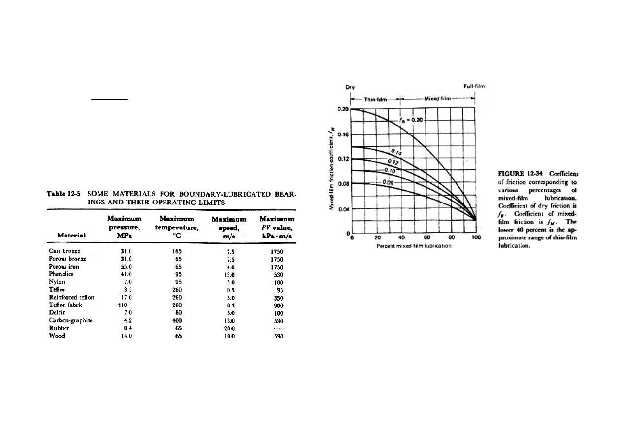
from Figure 12.34*) or the known
friction coefficient. Then:
78
0
20
65
1750
02
0
.
)
(
)
(
.
k
=
−
=
Then for the bearing:
C
C
T
T
)
(
.
.
)
T
T
(
)
V
P
(
f
k
B
B
A
B
bearing
M
D
D
65
55
20
1382
02
0
78
0
<
=
⇒
−
=
⇒
−
⋅
=
………..OK
5)
A 55-mm diameter bearing is 60mm long and has a central annular oil
groove of 5mm wide which is fed by SAE 30 oil at 40˚C and 450 kPa supply
pressure. The speed of the journal is 55 rps. The bearing is subjected to a
load of 4.5 kN while the radial clearance is 40 µm.
(a) Find the temperature rise in the lubricant, ∆T
c
.
(b) Find the total oil flow, Q
s
.

METU – ME 308 Machine Elements II – Spring 2005
7
(c) Find the minimum film thickness, h
o
.
SOLUTION
(a) The formulation for temperature rise is given in Equation 12.20* (be careful
the equation given in 5
th
edition is wrong):
)
.
(
r
P
C
W
S
f
c
r
.
T
S
H
c
2
4
2
5
1
1
5
1
ε
γ
∆
+
⋅
⋅
⋅
⋅
⋅
⎟
⎠
⎞
⎜
⎝
⎛
=
In this equation, S is not known, and also in S formulation µ is not known.
l
’
= ½(60-5) = 27.5 mm,
'
27.5
1/ 2
55
l
d
=
=
'
4.5
1488
4
4(0.0275)(0.0275)
W
P
kPa
rl
=
=
≈
So, iterations should be carried out to find µ and S.
1
ST
ITERATION:
Assume T
av
= 70
0
C as the first assumption:
Entering Figure 12.10*, 12.12** to the SAE 30 line:
Assume µ = 18 mPa.s →
2
2
27.5
0.018 (55)
0.315
0.040
1488000
r
N
S
c
P
µ
⋅
⎛ ⎞
⎛
⎞
=
=
=
⎜ ⎟
⎜
⎟
⎝ ⎠
⎝
⎠
From Figure 12.16*, 12.17**:
8
r
f
c
≈
From Figure 12.13*, 12.14**:
ε = 0.6
Then the temperature rise is:
2
2
4
2
4
2
1.5
1.5(8)(0.315)(4500)
1
127.4
(1 1.5 )
860(1760)(450000)(0.0275) (1 1.5(0.6) )
c
H
S
r
f
S W
c
T
C
C
P r
γ
ε
⎛
⎞⋅ ⋅
⎜
⎟
⎝
⎠
∆ =
=
=
⋅
⋅ ⋅
+
+
D
T
av
= T
1
+ (∆T
c
/2) = 40 + (127.4/2) = 103.7
0
C → First assumption failed.
Now assume T
av
= 85
0
C and repeat the procedure applied above.
The iterations are carried out until assumed and calculated T
av
’s are equal.
After several iterations:
µ = 13.5 mPa.s , S = 0.236, (r/c)f = 6.4, ε = 0.655 at T
av
= 76.5
0
C and
therefore
∆T
c
= 73
0
C
(b) From Equation 12.18*, 12.26**:
3
6 3
2
2
6
3
'
(450000)(0.0275)(40 10 )
(1 1.5 )
(1 1.5 (0.655) ) 3.67 10
/
3(0.0135)(0.0275)
3
s
s
P rc
Q
m
s
l
π
π
ε
µ
−
−
⋅
=
+
=
+
⋅
=
⋅
=3.67·10
3
mm
3
/s
(d) From Figure 12.13*, 12.14**:
h
o
/c = 0.345, since c = 40 µm;
h
o
= 0.345(40) = 13.8 µm.
6)
A self-contained journal bearing
having radial clearance of 40 µm
supports a load of 4 kN at a rotational
speed of 250 rpm. Diameter and length
of the bearing are both 70 mm. The
effective area of the housing surface can

METU – ME 308 Machine Elements II – Spring 2005
8
be taken as 20·d·l and for a reasonable temperature range the combined heat
transfer coefficient between housing and air equals to 11.4 W/m
2
K. SAE 20
type oil is used in the oil bath lubrication system of the bearing. What is the
housing temperature, if the ambient temperature is 25˚C ?
SOLUTION
If the energy balance is written, the dissipated heat from the housing should
be equal to the generated heat within the housing.
ω
π
⋅
⋅
⋅
⋅
=
⋅
=
−
+
⋅
d
W
f
V
F
)
T
T
(
B
A
C
A
L
1
……..Eqn. 12.22* 12.28**
where
T
L
is the average film temperature; ( not known )
T
A
is the temperature of surrounding air; (given as 25˚C)
C is combined coefficient of radiation and convection; ( for still air 11.4
W/m
2
K )
A is surface area of housing; (in this problem 20·d·l )
B is a constant which depends upon the lubrication system. For the oil bath
type lubrication and still air condition B changes between 1/5 and 2/5. In order
to be on the safe side and to get minimum heat dissipation and to find
maximum possible housing temperature B value is chosen as 2/5.
As T
L
= T
ave
and f depends on T
ave
, the equation above can be solved
iteratively.
Assuming T
av
=50˚C:
Dissipated heat;
3 2
(11.4)20(70.10 )
(
)
(50 25) 19.9
2
1
1
5
d
ave
A
C A
H
T
T
B
−
⋅
=
−
=
−
=
+
+
W
P = W /(dl) = 4000/(0.07)
2
= 0.816 MPa
Entering Figure 12.10*, 12.12** to the SAE 20 line (using T=50˚C, SAE 20 ):
µ=28 mPa.s
2
2
35
0.028
(250 / 60)
0.11
0.040
816000
r
N
mm
Pa
S
c
P
mm
Pa
µ
⋅
⎛ ⎞
⎛
⎞
=
=
=
⎜ ⎟
⎜
⎟
⎝ ⎠
⎝
⎠
From Figure 12.16*, 12.17** ( using S=0,11 , l/d=1 ):
2.9
0.0033
r
f
f
c
=
⇒ =
Generated heat;
3
250
0,0033 4000
70 10
12.1
60
60
g
N
rev
H
F V
f W
d
N
x
m
W
s
π
π
−
= ⋅ = ⋅ ⋅ ⋅ ⋅
=
⋅
⋅ ⋅
⋅
=
(H
g
= 12.1 W) ≠ (H
d
= 19.9 W)
As seen from the above inequality, the dissipated and generated heats are not
equal to each other. So, the iterations should be carried out until the heat-
balance is achieved. For some average temperature values following heat-
balance computation can be obtained.
Average Temperature(˚C) Dissipated Heat(Watt) Generated Heat ( Watt)
40 11,97
18,85
45
15,96
15,50
50
19,90
12,10
60
27,93
9,21
At the end of the iterations, T
L
= T
ave
= 44˚C.
Then:
(T
L
– T
H
) = B(T
H
–T
A
)
(44 – T
H
) = (2/5)(T
H
–25)
T
H
= 38.6˚C.
METU – ME 308 Machine Elements II – Spring 2005
9
Heat Dissipated vs.Heat Generated
11,97
15,96
19,90
27,93
15,50
18,85
12,10
9,21
0,00
5,00
10,00
15,00
20,00
25,00
30,00
40
45
50
60
Average Temperature( T)
Heat (W
att)
Heat Dissipated
Heat Generated
11.4 W/m
2
K
for still air
15.3 W/m
2
K
for average design practice
C =
33.5 W/m
2
K
for air moving at 2.5 m/s
Table 12.2*
Lubrication System
Conditions
Range of B
Moving air
1 – 2
Oil ring
Still air
0.5 – 1
Moving air
0.5 – 1
Oil Bath
Still air
0.2 – 0.4
*
METU – ME 308 Machine Elements II – Spring 2005
10
BOUNDARY-LUBRICATED BEARINGS
(
)
B
A
M
k T
T
PV
f
−
=
(12.23)*
where
P
= load per unit projected bearing area, kPa
V
= surface velocity of journal relative to bearing surface, m/s
T
A
= ambient air temperature,
0
C
T
B
= ambient air temperature,
0
C
f
M
= coefficient of mixed-film friction
*
*
Document Outline
- ME 308 – MACHINE ELEMENTS II
- “LUBRICATION & JOURNAL BEARINGS”
- Taking γ = 860 kg/m3 and CH = 1760 j/kg˚C:
- ΔT = 190 ˚C
Wyszukiwarka
Podobne podstrony:
Cylinder lubrication setting
Open Access and Academic Journal Quality
4 Fuel and Lubrication System
Electrochemical properties for Journal of Polymer Science
journal design
H000441 C Eng Lubrication unit
nachi dg bearings
75 1067 1073 Elimination of Lubricants in Industries in Using Self Lubricating Wear Resistant
Derrida, Jacques «Hostipitality» Journal For The Theoretical Humanities
Huang et al 2009 Journal of Polymer Science Part A Polymer Chemistry
17 Lubrication
Ionic liquids solvent propert Journal of Physical Organic Che
1848 Journal?s oesterreichischen Lloyd
Funding open access journal
09 Spring QUATERLY JOURNAL
BEARINGS
bearing capacity of spatially random c f soils
Impact Journalism Day 2015
więcej podobnych podstron