Chapter 13: Rolling-Element Bearings
Covered in this class:
•13.1 - 13.3
•13.4 (Figures only)
•Tables 13.6 and 13.8
•13.9 Most importantly
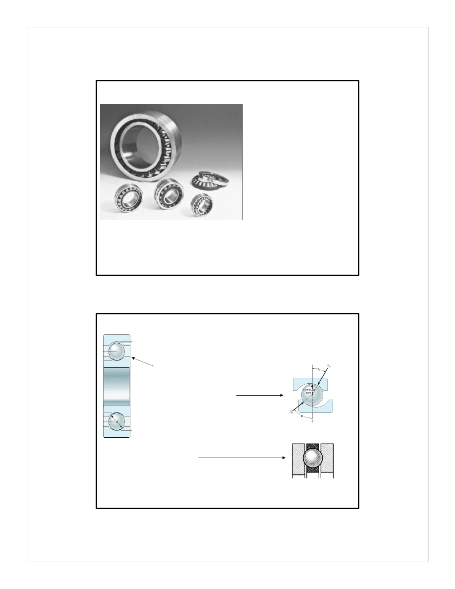
Bearing types:
• Ball bearings
– Deep groove (Conrad)
– Angular contact
– Thrust
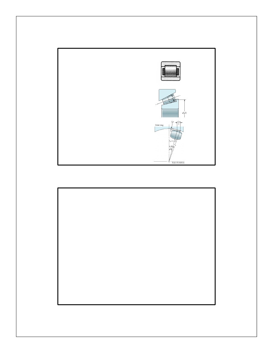
Bearing types
• Cylindrical roller bearings
• Tapered roller bearings
• Spherical roller bearings
Characteristics of Ball Bearings
Table 13.1 Characteristics of representative radial ball bearings
Table 13.2 Characteristics of representative angular-contact ball
bearings
Table 13.3 Characteristics of representative thrust ball bearings
Table 13.4 Characteristics of representative cylindrical roller
bearings
Table 13.5 Characteristics of representative spherical roller bearings
Read Example 13.1 Selection of bearing types
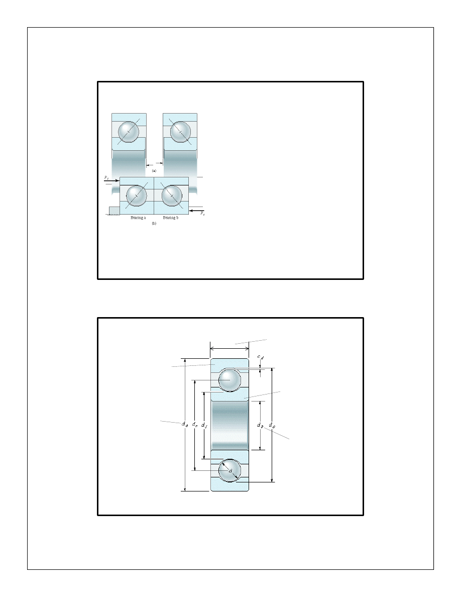
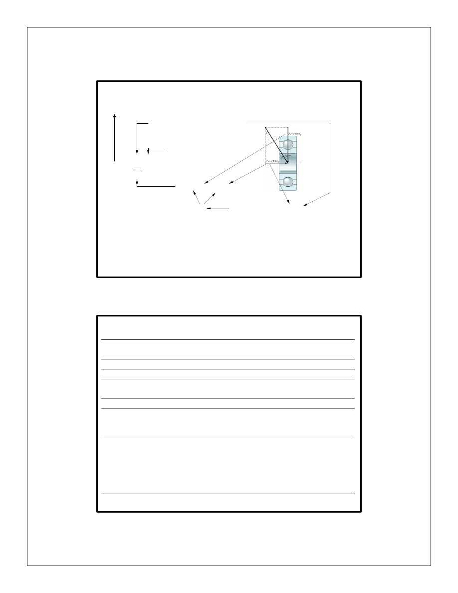
Preloading for stiffness
Figure 13.17 Angular-contact
bearings in back-to-back
arrangement, shown (a)
individually as manufactured
and (b) as mounted with preload.
Ball Bearings, important dimensions
Text Reference: Figure 13.1, page 550
Outside
diameter
Inside
diameter
b
w
Width
Outer race
Inner race
Important skills
Figure 13.20
Typical fatigue
spall.
Text Reference: Figure 13.20, page 586
• How to predict fatigue failure: use empirical
formulae.
• Select bearing type
• Select bearing size
• Predict bearing life
(failure is usually due to
fatigue)
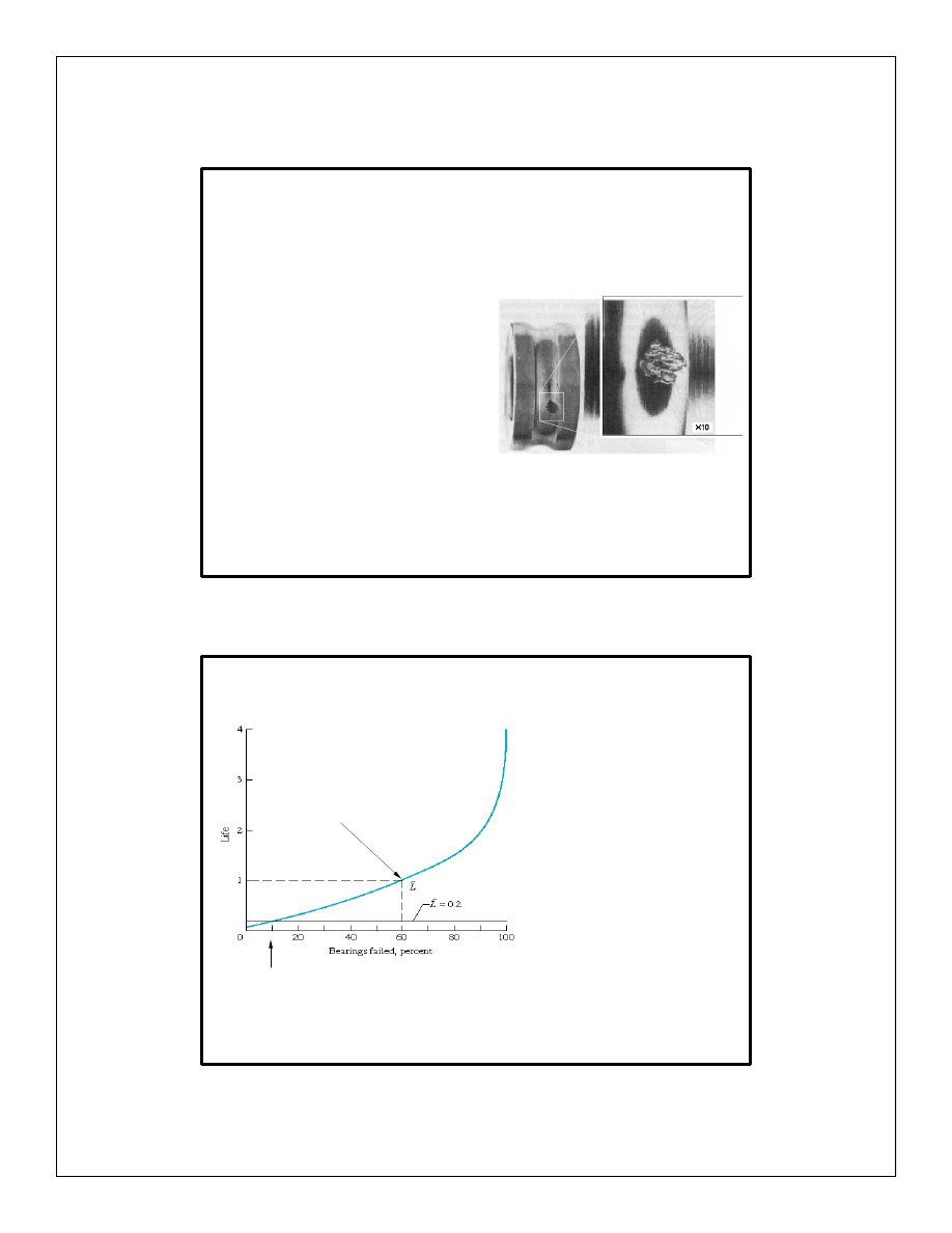
Fatigue Life
Figure 13.21 Distribution of
bearing fatigue failures.
Text Reference: Figure 13.21, page 580
• For a lower load, the number of cycles to cause
10% failure (L
10
) will be higher.
10% of the bearings fail at 0.2 million cycles
60% of the bearings
fail at 1 million cycles
Predicting fatigue life
k
m
P
C
L
=
10
• Life in millions of cycles is (Eq. 13.84)
Table 13.6 for deep groove ball
Table 13.7 for cylindrical roller
3.0 for deep groove ball
3.3 for cylindrical roller
P = X P
r
+ Y P
a
(Eq.13.86)
Table 13.9 for deep groove ball
Table 13.10 for thrust bearings
X and Y depend on P
a
/C
0
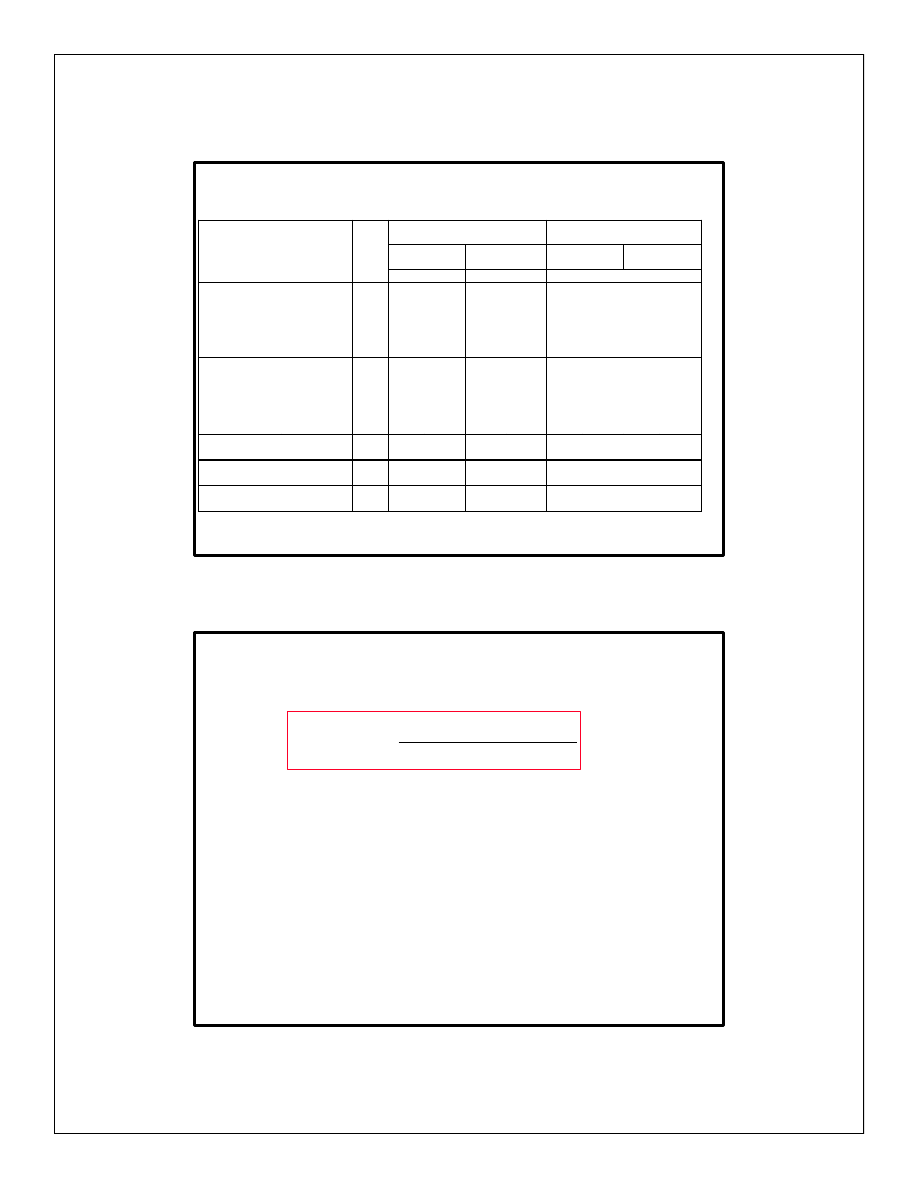
Single Row Deep Groove Ball Bearings,
Table 13.6
Pr incipal Dim ensions
Basic load ratings
Allowable
load lim it
Speed ratings
Abutment and fillet
Dim ensions
d
b
d
a
b
w
dynam ic
C
static
C
0
w
all
grease
oil
D
b,min
D
a,ma x
r
a,max
m m
in
m m
in
m m
in
N
lbf
rpm
m m
in
m m
in
m m
in
2.5
0.0984
8
0.3150
2.8
0.1102
319
71.7
106
23.8
4
0.899
67000
80000
3.7
0.146
6.8
0.268
0.1
0.004
5
0.1969
11
0.4331
3
0.1181
637
143
255
57.3
11
2.47
53000
63000
6.2
0.244
9.8
0.386
0.1
0.004
19
0.7480
6
0.2362
1720
387
620
139
26
5.85
36000
43000
7
0.276
17
0.669
0.3
0.012
7
0.2756
14
0.5512
3.5
0.1378
956
215
400
89.9
17
3.82
45000
53000
8.2
0.323
12.8
0.504
0.1
0.004
10
0.3937
19
0.7480
5
0.1969
1380
310
585
132
25
5.62
36000
43000
12
0.472
17
0.669
0.3
0.012
26
1.0236
8
0.3150
4620
1040
1960
441
83
18.7
30000
36000
12
0.472
24
0.945
0.3
0.012
35
1.3780
11
0.4331
8060
1810
3400
764
143
32.1
20000
26000
14
0.551
31
1.220
0.6
0.024
15
0.5906
24
0.9449
5
0.1969
1560
351
800
180
34
7.64
28000
34000
17
0.669
22
0.866
0.3
0.012
28
1.1024
7
0.2756
4030
906
2040
459
85
19.1
24000
30000
17
0.669
26
1.024
0.3
0.012
32
1.2598
8
0.3150
5590
1260
2850
641
120
27.0
22000
28000
17
0.669
30
1.181
0.3
0.012
32
1.2598
9
0.3543
5590
1260
2850
641
120
27.0
22000
28000
17
0.669
30
1.181
0.3
0.012
35
1.3780
11
0.4331
7800
1750
3750
843
160
36.0
19000
24000
19
0.748
31
1.220
0.6
0.024
42
1.6535
13
0.5118
11400
2560
5400
1210
228
51.3
17000
20000
20
0.787
37
1.457
1
0.039
Note: See additional Data in SKF Folder on CD.
Text Reference: Table 13.6, page 578
Capacity Formulas for Radial and Angular Bearings
Table 13.9
Bearing type
e
Single row bearings
Double row bearings
Pa/Pr<e
Pa/Pr>e
Pa/Pr<e
Pa/Pr>e
X
Y
X
Y
X
Y
X
Y
Deep groove
ball bearings
P
a
/C
0
=0.025
P
a
/C
0
=0.04
P
a
/C
0
=0.07
P
a
/C
0
=0.13
P
a
/C
0
=0.25
P
a
/C
0
=0.50
0.22
0.24
0.27
0.31
0.37
0.44
1
1
1
1
1
1
0
0
0
0
0
0
0.56
0.56
0.56
0.56
0.56
0.56
2.0
1.8
1.6
1.4
1.2
1
Angular contact
ball bearings
β
=20°
β
=25°
β
=30°
β
=35°
β
=40°
β
=45°
0.57
0.68
0.80
0.95
1.14
1.33
1
1
1
1
1
1
0
0
0
0
0
0
0.43
0.41
0.39
0.37
0.35
0.33
1
0.87
0.76
0.66
0.57
0.50
1
1
1
1
1
1
1.09
0.92
0.78
0.66
0.55
0.47
0.70
0.67
0.63
0.60
0.57
0.54
1.63
1.41
1.24
1.07
0.93
0.81
Self-aligning
ball bearings
1.5 x
tan
β
1
0.42 x
cot
β
0.65
0.65 x
cot
β
Spherical roller
bearings
1.5 x
tan
β
1
0.45 x
cot
β
0.67
0.67 x
cot
β
Tapered roller
bearings
1.5 x
tan
β
1
0
0.40
0.40 x
cot
β
1
0.42 x
cot
β
0.67
0.67 x
cot
β
Table 13.9 Capacity formulas for rectangular and elliptical conjunctions for radial and
angular bearings.
Text Reference: Table 13.9, page 592
Life in hours
• The resulting life is L
10
, meaning the number of cycles when 10% of the bearings
fail.
•
L
10
means Survival rate S = 0.9.
(L
50
means S = 0.5, etc)
• Life in hours is
b
N
L
L
60
)
cycles
million
in
(
10
)
hours
in
(
10
6
10
=
(13.85)
N
b
= rotational speed (in rpm)
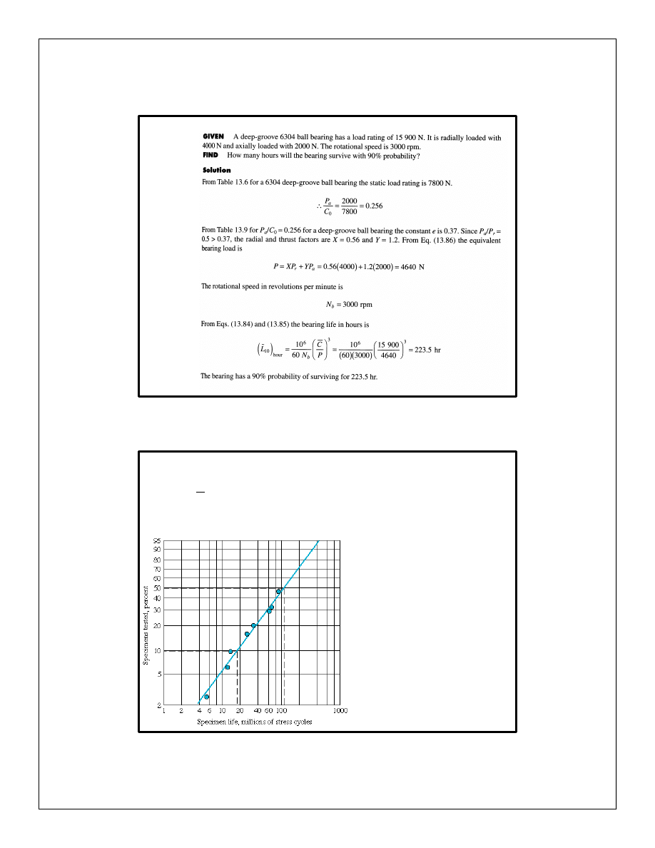
Example 13.8 p 595
Life other than L
10
Figure 13.23 Typical Weibull
plot of bearing fatigue failures.
Text Reference: Figure 13.23, page 590
results in the number of cycles that causes
10% failure (L
10
).
k
m
P
C
L
=
10
• To predict the
number of cycles
that causes x%
failure (L
x
), use the
Weibull plot.
• See Example 13.9.
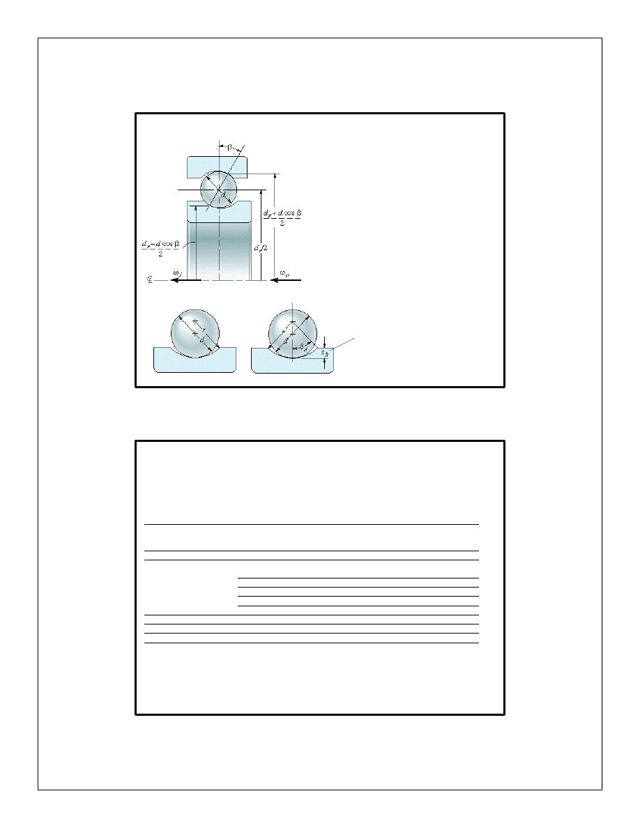
Effect of contact angle (optional)
Figure 13.6
Text Reference: Figure 13.6, page 555
Shoulder height
• Contact angle
β
determines the radial and
thrust factors in
P = X P
r
+ Y P
a
(Eq.13.86)
• To estimate
β
,
see
subsection 13.4.1.3.
Radial and Thrust Factors
Bearing Type
Single
Row
Double
Row
X
0
Y
0
X
0
Y
0
Radial deep-groove ball
0.6
0.5
0.6
0.5
Radial angular-contact
ball
β
=20°
0.5
0.42
1
0.84
β
=25°
0.5
0.38
1
0.76
β
=30°
0.5
0.33
1
0.66
β
=35°
0.5
0.29
1
0.58
β
=40°
0.5
0.26
1
0.52
Radial self-aligning ball
0.5
0.22cot
β
1
0.44cot
β
Radial spherical roller
0.5
0.22cot
β
1
0.44cot
β
Radial tapered roller
0.5
0.22cot
β
1
0.44cot
β
Table 13.8 Radial factor X
0
and thrust factor Y
0
for statically stressed radial
bearings.
Text Reference: Table 13.8, page 580
Radial and Thrust Factors
Bearing type
e
Single acting
Double acting
P
a
/P
r
>e
P
a
/P
r
<e
P
a
/P
r
>e
X
Y
X
Y
X
Y
Thrust
ball
β
=45°
β
=60°
β
=75°
1.25
2.17
4.67
0.66
0.92
1.66
1
1
1
1.18
1.90
3.89
0.59
0.55
0.52
0.66
0.92
1.66
1
1
1
Spherical roller
thrust
1.5tan
β
tan
β
1
1.5tan
β
0.67
tan
β
1
Tapered roller
1.5tan
β
tan
β
1
1.5tan
β
0.67
tan
β
1
Table 13.10 Radial factor X and thrust factor Y for thrust bearings.
Text Reference: Table 13.10, page 592
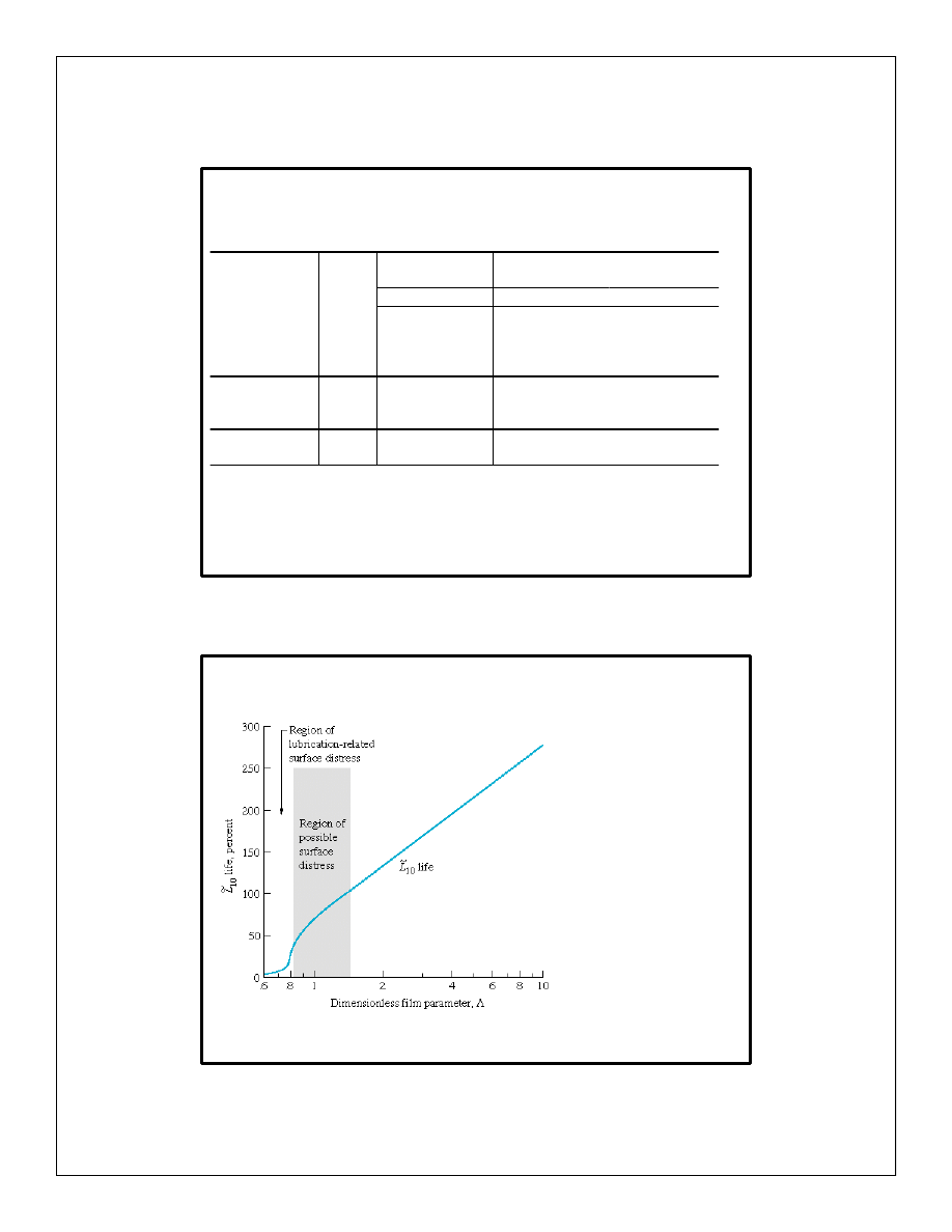
Fatigue Life vs. Film Parameter
Figure 13.24 Group fatigue
life L
10
as function of
dimensionless film
parameter. [From Tallian
(1967)]
Text Reference: Figure 13.24, page 594
Wyszukiwarka
Podobne podstrony:
nachi dg bearings
bearing capacity of spatially random c f soils
nachi tr bearings
Lecture 8 Bearings
Closure to Discussion by R Popescu on bearing capacity of spatially random c f soils
nachi dg bearings
SR20DET Bearing grades
nachi tr bearings
Closure to Discussion by R Popescu on bearing capacity of spatially random c f soils
TimKen com Wheel Bearing Replacement Tips
bearing capacity of spatially random c f soils
Anthony, Piers Incarnations of Immortality 02 Bearing an Hourglass
EL MOTOR BEARINGS
The exploitation of carnivores and other fur bearing mammals during
lubrication&Journal Bearings
Paranormal Dating Agency 2 Geek Bearing Gifts Milly Taiden
więcej podobnych podstron