
1
Bearings for Bridges
Dr. Shahzad Rahman
NWFP University of Engg & Technology,
Peshawar
2
Bridge Bearings

3
Bridge Bearings
Function Of Bearings
Bridge bearings are used to transfer
forces from the superstructure to the
substructure, allowing the following
types of movements of the
superstructure:
Translational movements; and
Rotational movements

4
Bridge Bearings
Until the middle of this century, the bearings
used consisted of following types:
Pin
Roller
Rocker
Metal sliding bearings

5
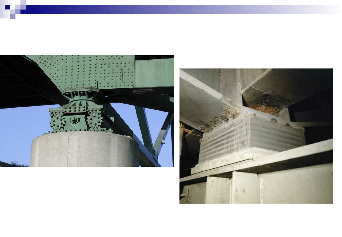
Pin Bearing
A pin bearing is a type of fixed bearings that
accommodates rotations through the use of a steel
Translational movements are not allowed.
The pin at the top is composed of upper and lower
semicircularly recessed surfaces with a solid circular
pin placed between.
Usually, there are caps at both ends of the pin to keep
the pin from sliding off the seats and to resist uplift
loads if required.
The upper plate is connected to the sole plate by
either bolting or welding. The lower curved plate sits
on the masonry plate.
6
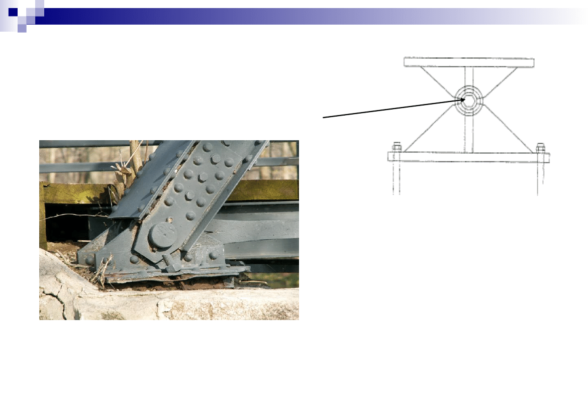
Pin Bearing
Steel Pin
• Rotational Movement is allowed
• Lateral and Translational Movements are
Restricted
7
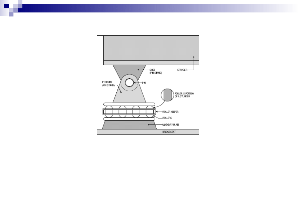
Roller Type Bearings
Multiple Roller Bearing
Single Roller Bearing
• AASHTO requires that expansion rollers be equipped with “substantial
side bars” and be guided by gearing or other means to prevent lateral
movement, skewing, and creeping (AASHTO 10.29.3).
•
A general drawback to this type of bearing is its tendency to
collect dust
and debris.

8
Roller Type Bearings
Roller Type Bearing with Gear Arrangement
• Longitudinal movements are allowed
• Lateral Movements and Rotations are
Restricted
9
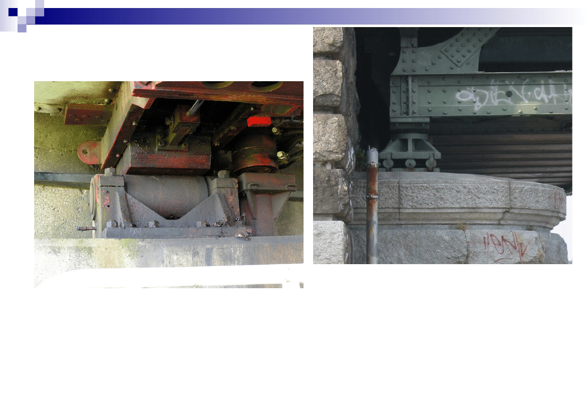
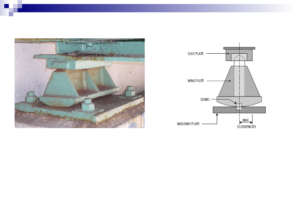
Rocker Type Bearing
• A rocker bearing is a type of expansion bearing that comes in
a great variety.
• It typically consists of a pin at the top that facilitates
rotations, and a curved surface at the bottom that
accommodates the translational movements
• Rocker and pin bearings are primarily used in steel bridges.
10
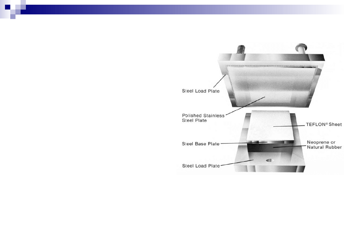
Sliding Bearings
• A sliding bearing utilizes one plane
metal plate sliding against another to
accommodate translations.
• The sliding bearing surface produces a
frictional force that is applied to the
superstructure, substructure, and the
bearing itself.
• To reduce this friction force, PTFE
(polytetrafluoroethylene) is often used
as a sliding lubricating material. PTFE
is sometimes referred to as Teflon,
named after a widely used brand of
PTFE
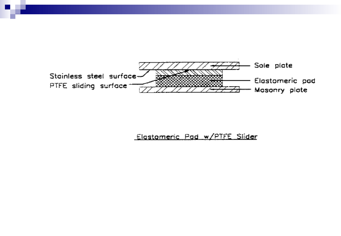
11
Sliding Bearings
• Sliding Bearings be used alone or more often used as a component in
other types of bearings
• Pure sliding bearings can only be used when the rotations caused by
the deflection at the supports are negligible. They are therefore
limited to a span length of 15 m or less by ASHTTO [10.29.1.1]
12
Knuckle Pinned Bearing
• It is special form of Roller Bearing in which the Knuckle pin is provided for
easy rocking. A knuckle pin is inserted between the top and bottom
casting. The top casting is attached to the Bridge superstructure, while the
bottom casting rests on a series of rollers
• Knuckle pin bearing can accommodate large movements and can
accommodate sliding as well as rotational movement
13
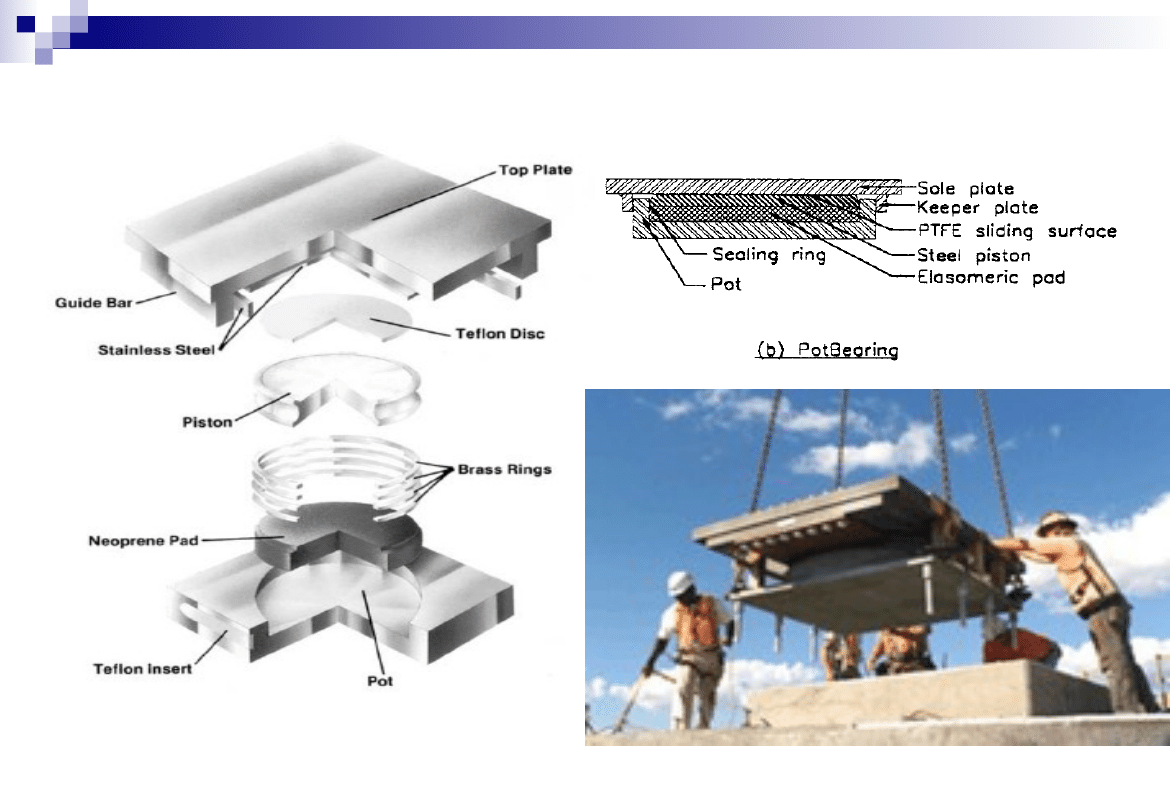
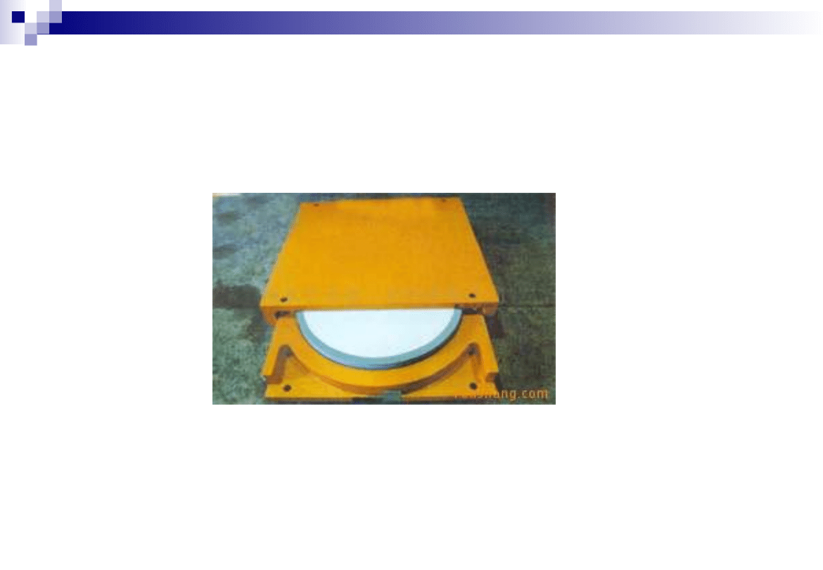
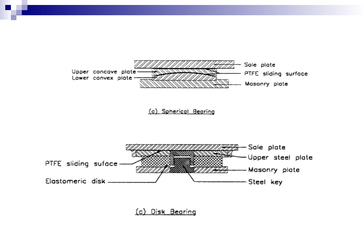
Pot Bearings
14
Pot bearing

15
Pot Bearings
A POT BEARING consists of a shallow steel
cylinder, or pot, on a vertical axis with a
neoprene disk which is slightly thinner than the
cylinder and fitted tightly inside.
A steel piston fits inside the cylinder and bears
on the neoprene.
Flat brass rings are used to seal the rubber
between the piston and the pot.
The rubber behaves like a viscous fluid flowing
as rotation may occur.
Since the bearing will not resist bending
moments, it must be provided with an even
bridge seat.
16
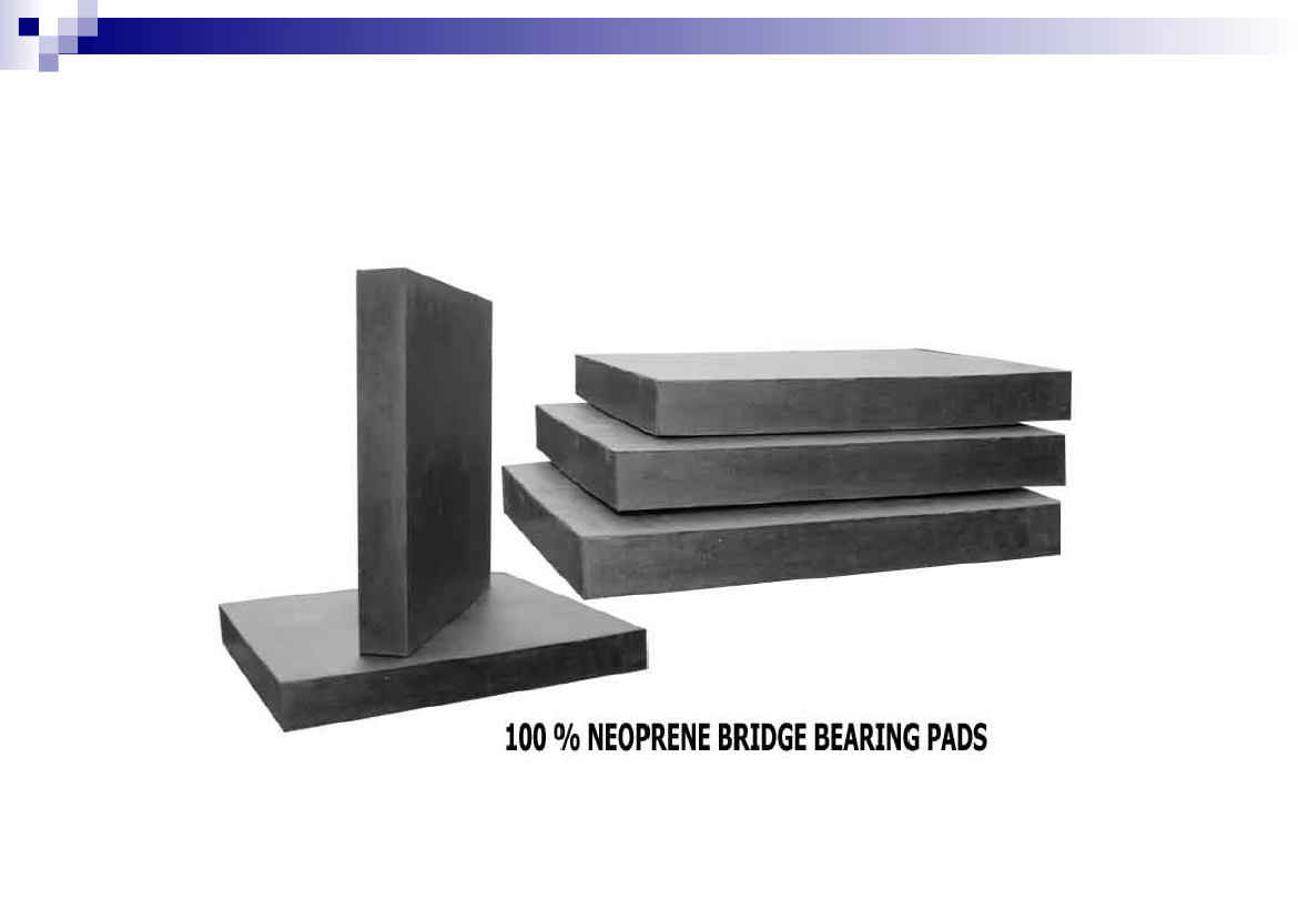
Plain Elastomeric Bearings
17
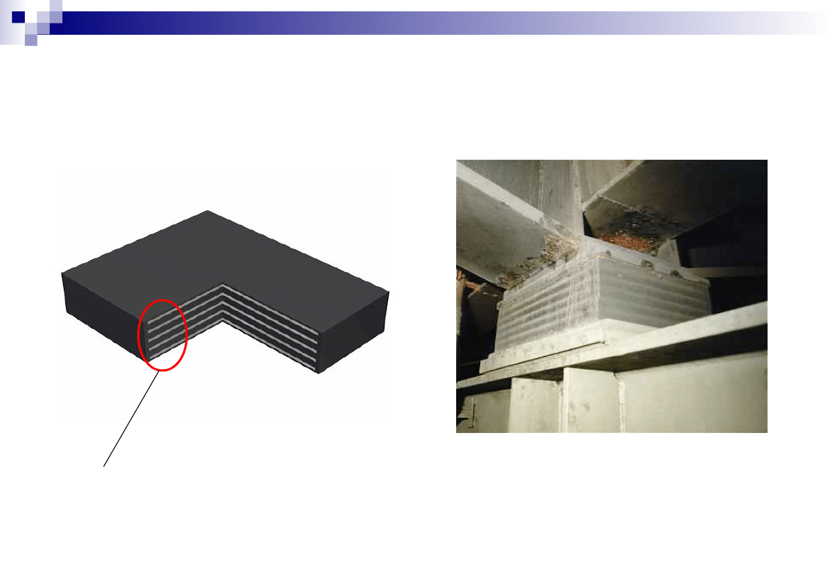
Laminated Elastomeric Bearings
Elastomeric material interspersed with steel plates
18
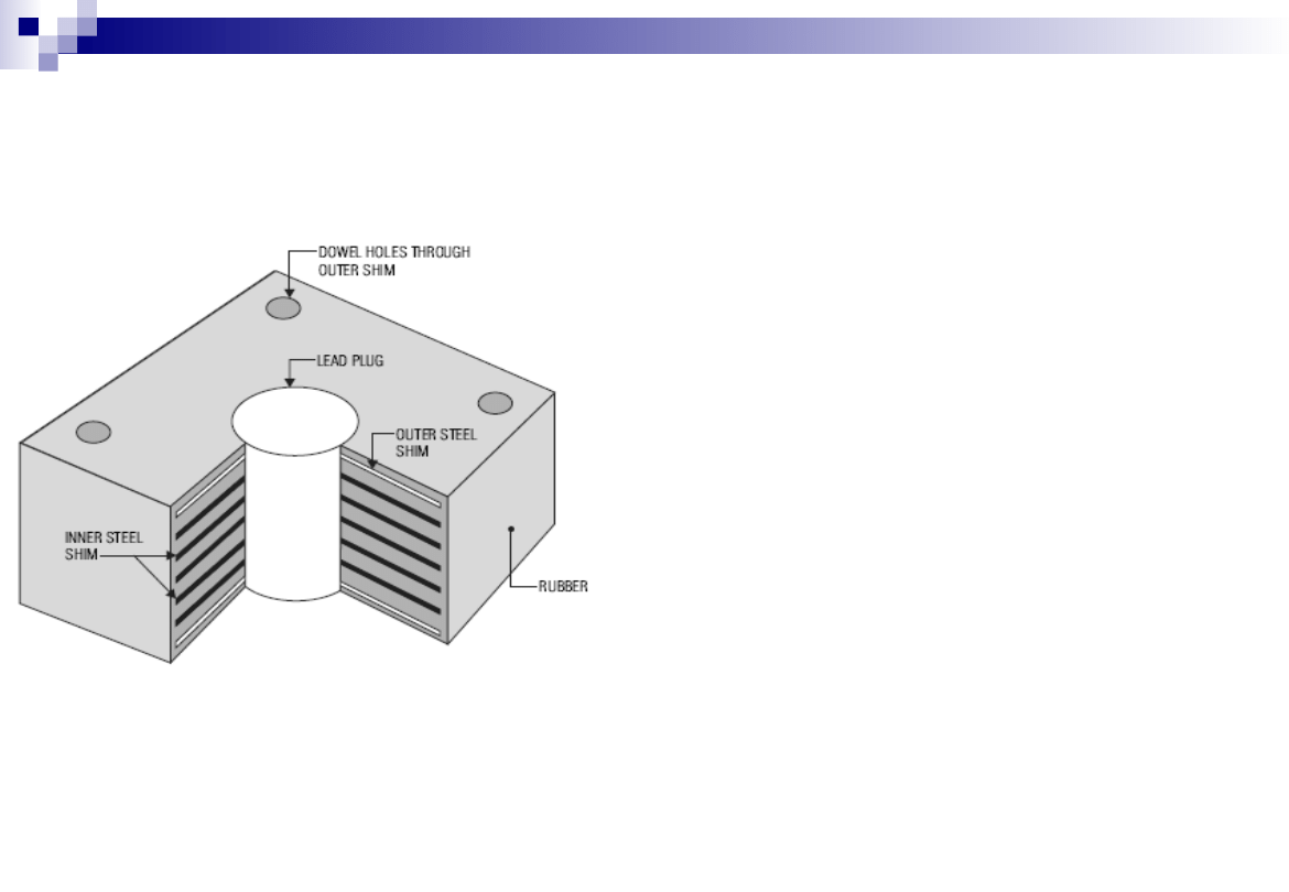
Laminated Elastomeric Bearings
• consist of a laminated elastomeric
bearing equipped with a lead cylinder
at thecenter of the bearing.
• The function of the rubber-steel
laminated portion of the bearing is to
carry the weight of the structure and
provide post-yield elasticity.
• The lead core is designed to deform
plastically, thereby providing damping
energy dissipation.
• Lead rubber bearings are used in
seismically active areas because of
their performance under earthquake
loads.
19
Other Types of Bearings
20
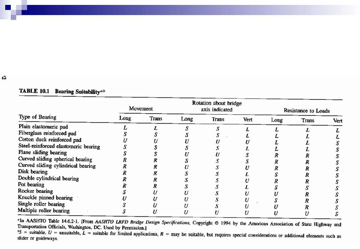
Selection of Bearing Type
AASHTO LRFD provides guidelines for selection of
suitable bearings for bridges as per requirements in
Table 14.6.2-1
21
Selection of Bearing Type
Long
Trans
Long
Trans
Vert
Long
Trans
Vert
S
L
R
U
L
L
S
S
L
L
L
L
2
6
0
0
18
S
S
S
S
L
L
L
L
4
4
0
0
20
U
U
U
U
U
L
L
S
1
2
0
5
7
S
S
S
S
L
L
L
S
5
3
0
0
21
S
S
U
U
S
R
R
S
4
0
2
2
14
R
R
S
S
S
R
R
S
4
0
4
0
16
R
R
U
S
U
R
R
S
2
0
4
2
10
R
R
S
S
L
S
R
S
4
1
3
0
17
R
R
S
S
U
R
R
S
3
0
4
1
13
R
R
S
S
L
S
S
S
5
1
2
0
19
S
U
U
S
U
U
R
S
3
0
1
4
10
U
U
U
S
U
S
R
S
3
0
1
4
10
S
U
U
S
U
U
R
S
3
0
1
4
10
S
U
U
U
U
U
U
S
2
0
0
6
6
Score
Rank
Type of Bearing
S
=
suitable,
U
=
unsuitable,
L
=
suitable for limited applications,
R
=
may be suitable, but requires special considerations or additional
elements such as slider or guideways.
Bearing Suitability:
Disk bearing
Pot bearing
Rocker bearing
AASHTO Table 14.6.2-1
Axis indicated
Single roller bearing
Multiple roller bearing
Rotation about bridge
Resistance to Loads
Curved sliding spherical
bearing
Curved sliding cylindrical
bearing
Double cylindrical bearing
Knuckle pinned bearing
Fiberglass reinforced pad
Cotton duck reinforced pad
Steel-reinforced elastomeric
bearing
Plane sliding bearing
Movement
Plain elastomeric pad
22
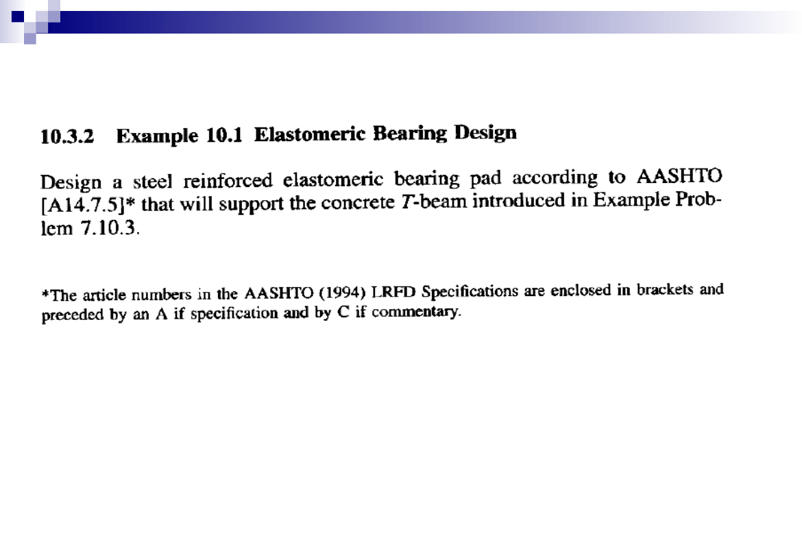
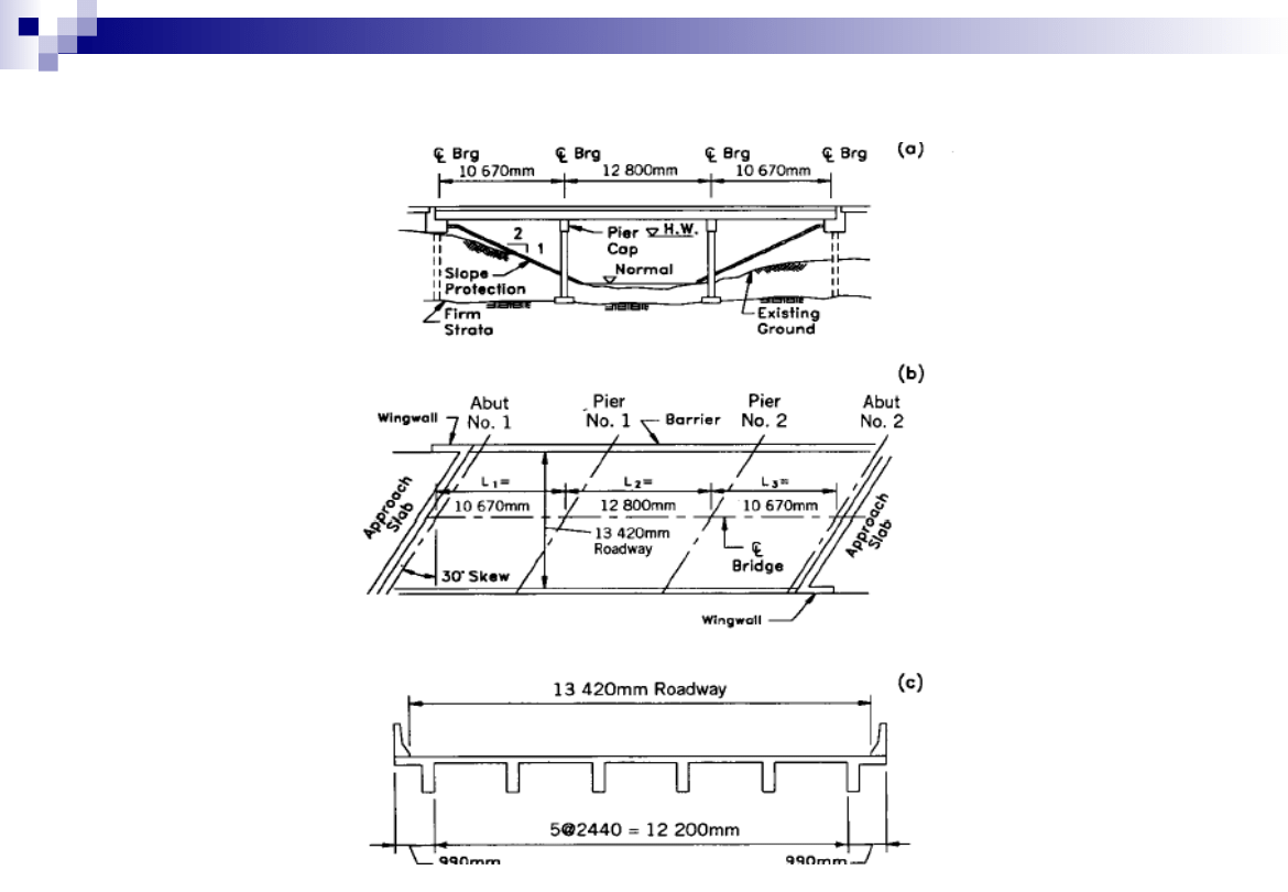
Elastomeric Bearing Design -Example
23
Elastomeric Bearing Design -Example
24
Elastomeric Bearing Design -Example
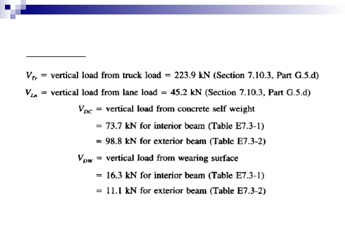
Loading Data
25
Elastomeric Bearing Design -Example
Corrected for skew
mgr = r
skew
x mg
Where,
r
skew
= Correction Factor for Skew
mg = Uncorrected Distribution Factor neglecting skew

26
Elastomeric Bearing Design -Example
826
.
0
MI
V
mg
Uncorrected Distribution Factor =
For Shear, Interior Beams
762
.
0
SE
V
mg
Uncorrected Distribution Factor =
For Shear, Exterior Beams
746
.
0
MI
M
mg
Uncorrected Distribution Factor =
For Moment, Interior Beams
762
.
0
SE
M
mg
Uncorrected Distribution Factor =
For Moment, Exterior Beams

27
Elastomeric Bearing Design -Example
Correction Factor for Skew
For skewed bridges the Distribution Factor for Shear may be modified by
Multiplying it with a Modification Factor given as: [A4.6.2.2.3 c-1]
tan
2
.
0
0
.
1
3
.
0
3
Kg
Lts
r
skew
o
30
0
.
1
3
Kg
Lts
115
.
1
)
577
.
0
(
0
.
1
2
.
0
0
.
1
3
.
0
skew
r

28
Elastomeric Bearing Design -Example
Correction Factor for Moment
For skewed bridges the Distribution Factor for Moment may be modified by
Multiplying it with a Modification Factor given as: [A4.6.2.2.2 e]
5
.
0
25
.
0
3
1
5
.
1
1
25
.
0
)
(tan
0
.
1
L
S
Lts
Kg
c
c
r
skew
o
30
mm
S
mm
L
Lts
Kg
2440
,
670
,
10
,
0
.
1
3
948
.
0
)
30
(tan
0
.
1
5
.
1
1
c
r
skew
12
.
0
10670
2400
1
25
.
0
5
.
0
25
.
0
1
x
x
c
29
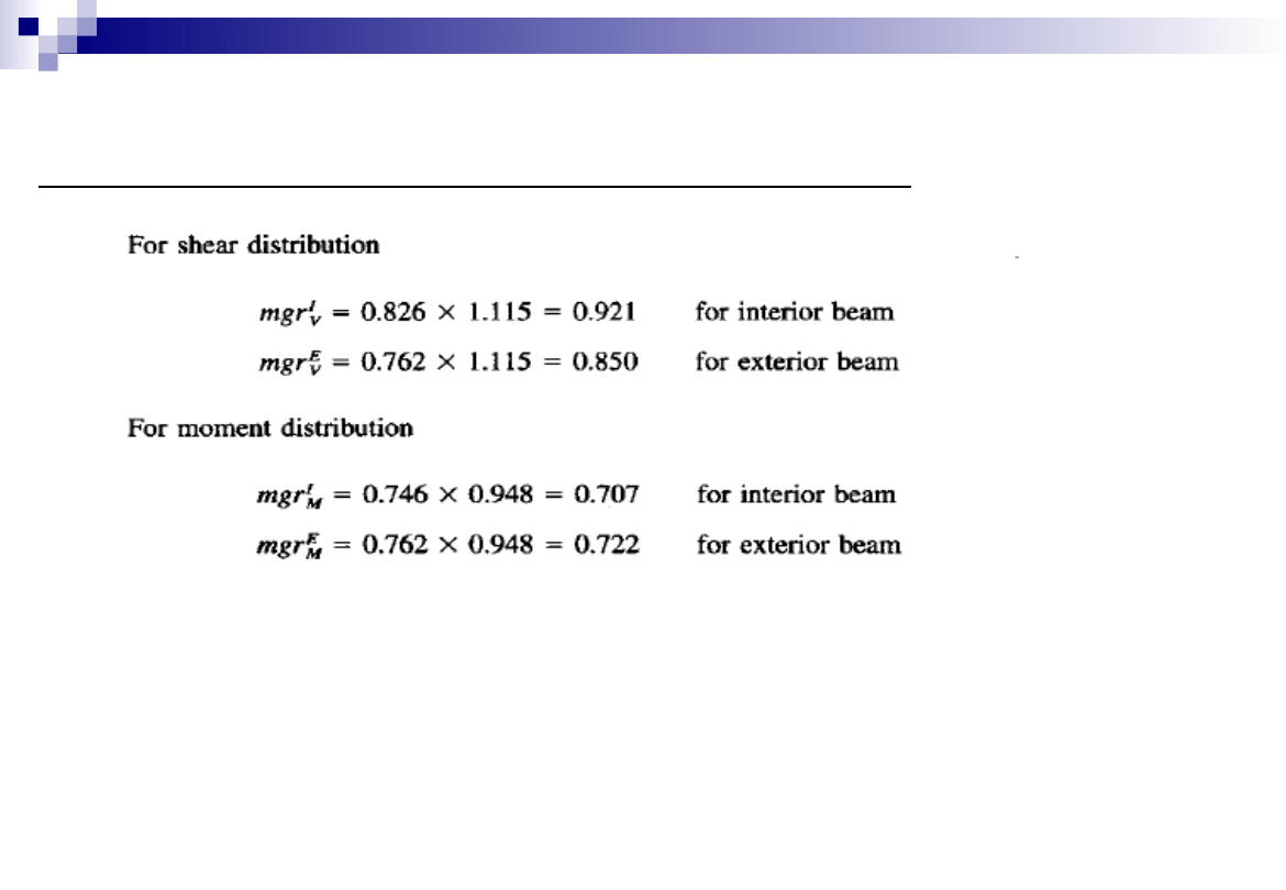
Elastomeric Bearing Design -Example
Modified Distribution Factors for Shear and Moment
30
Elastomeric Bearing Design -Example
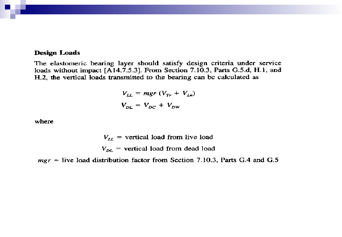
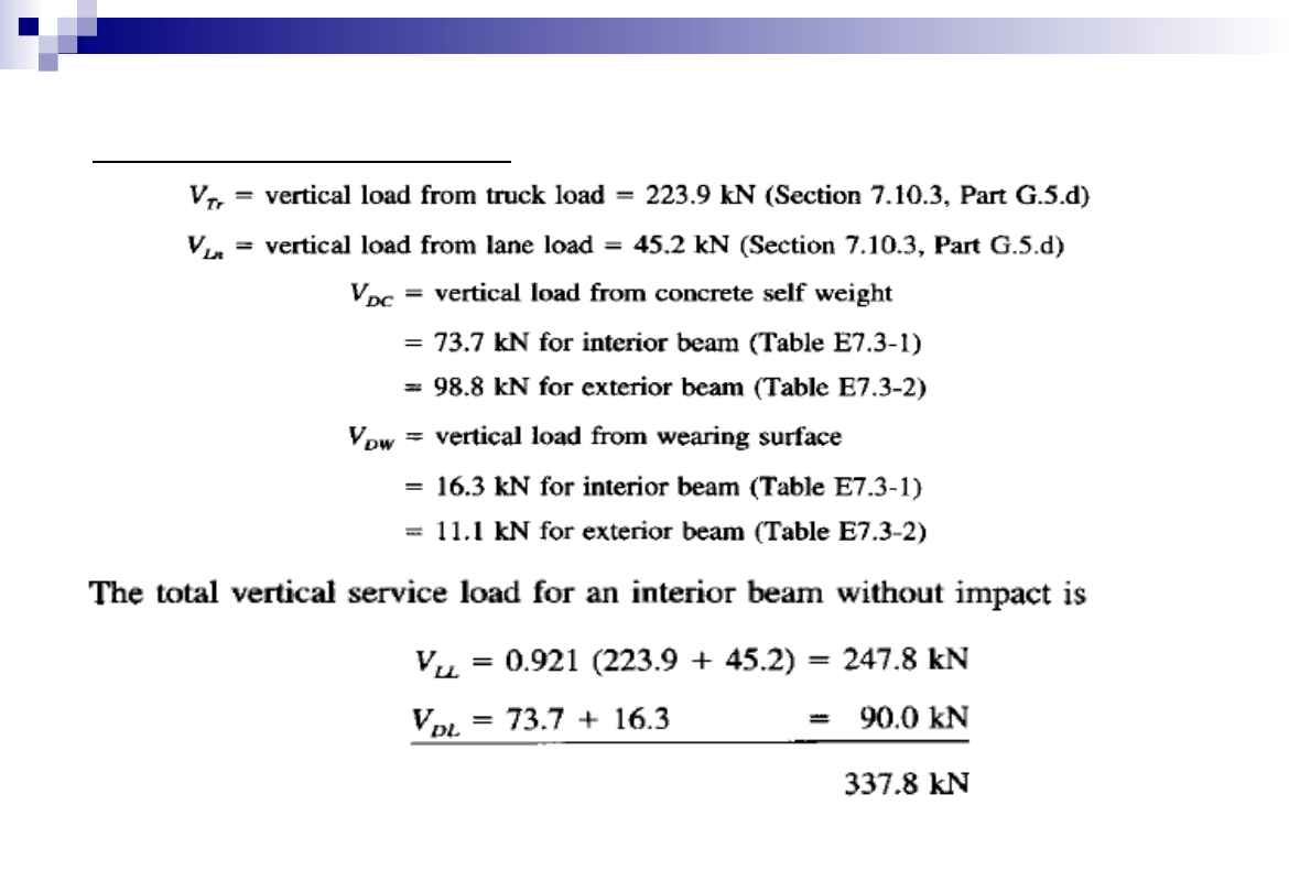
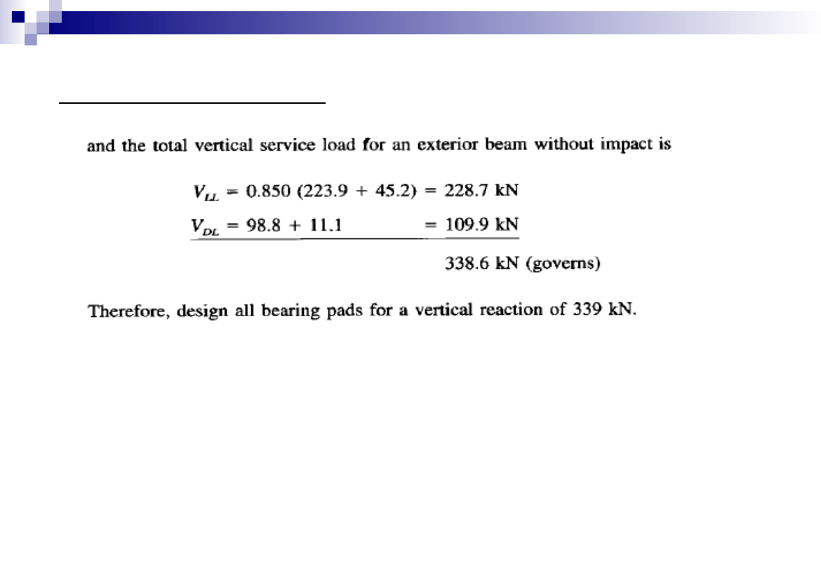
Bearing Load Calculation
31
Elastomeric Bearing Design -Example
Bearing Load Calculation
32
Elastomeric Bearing Design -Example
33
Elastomeric Bearing Design -Example
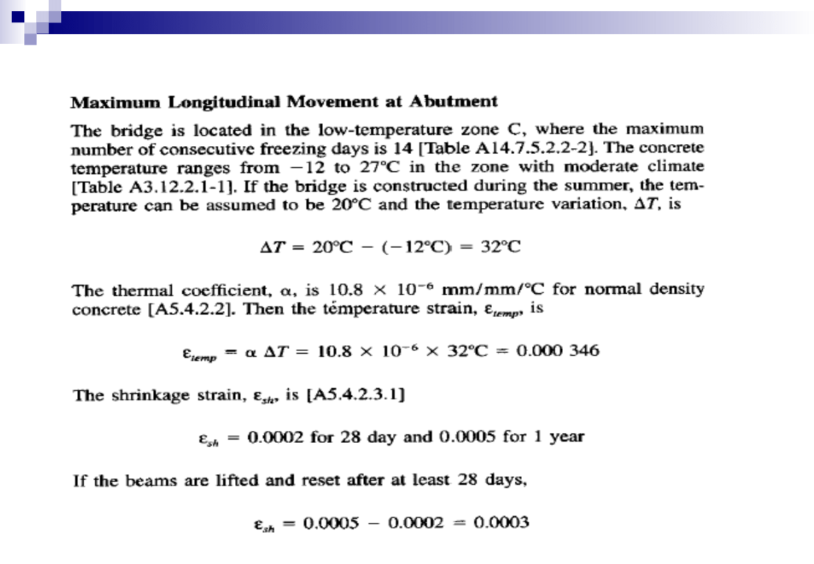
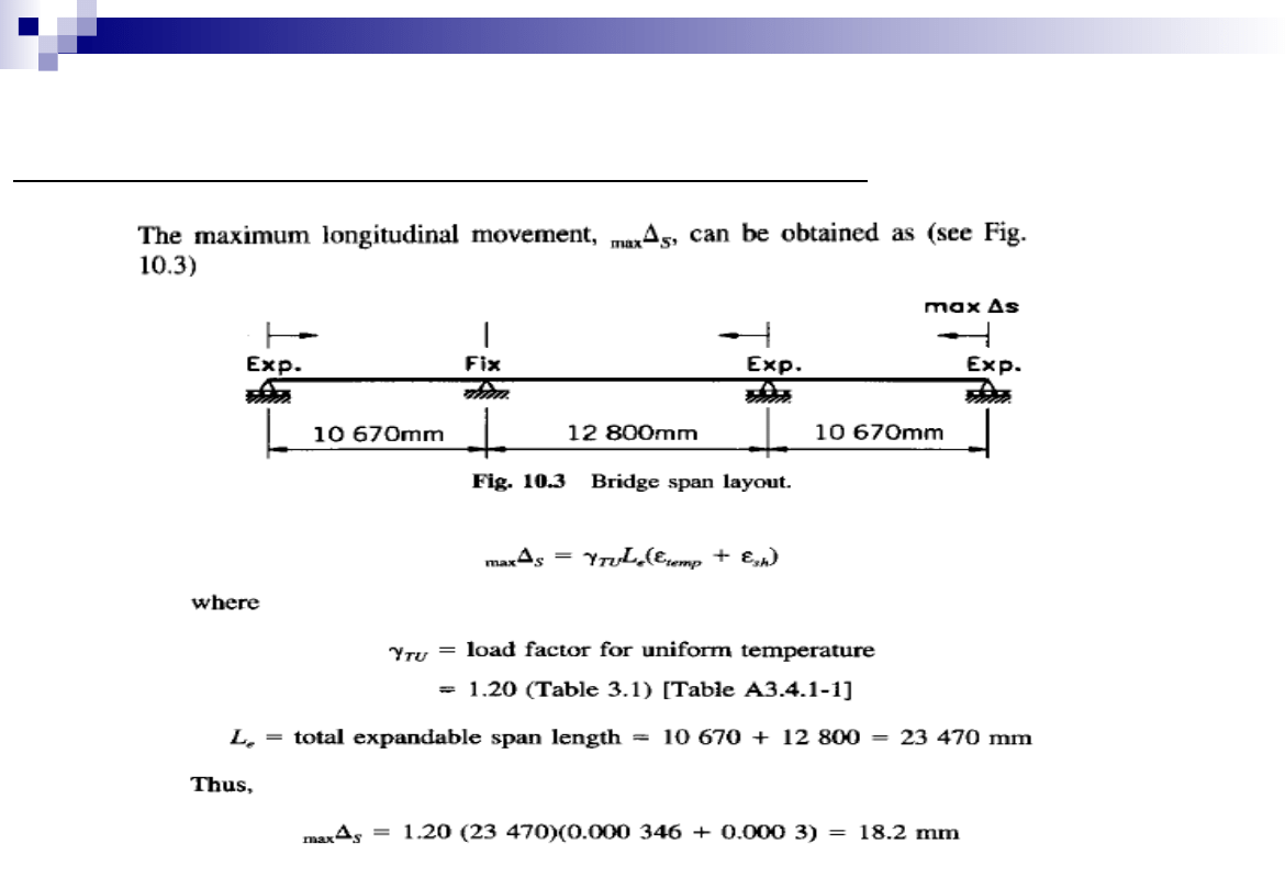
Maximum Longitudinal Movement at the Abutment
34
Elastomeric Bearing Design -Example
35
Elastomeric Bearing Design -Example
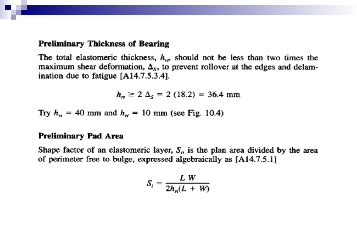
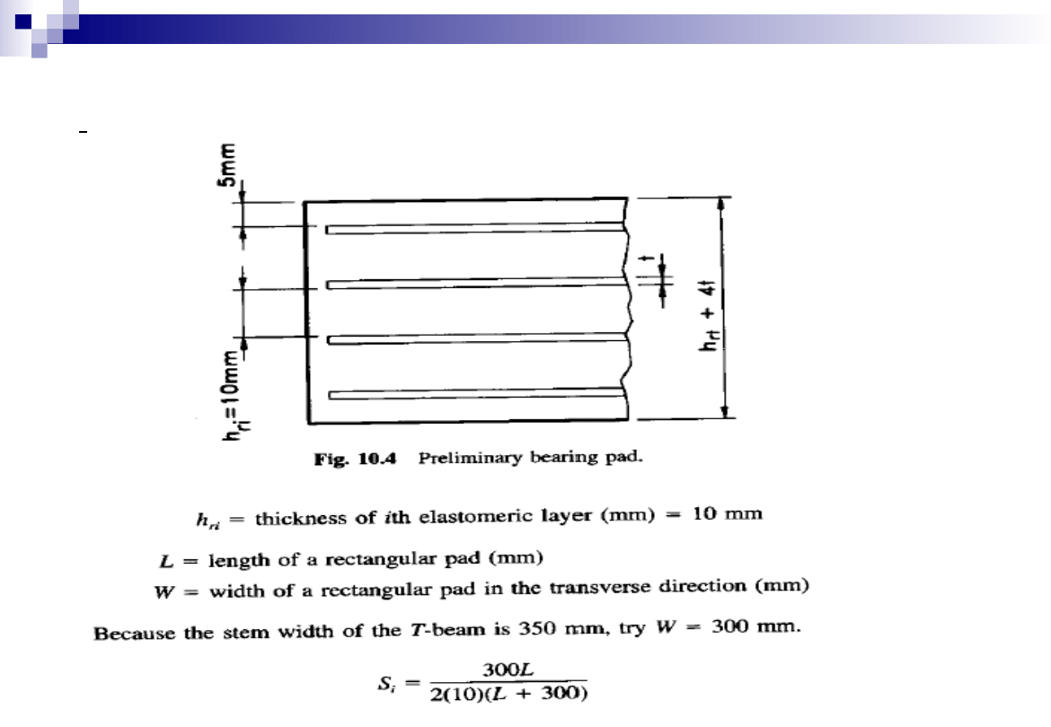
Preliminary Thickness of Bearing
36
Elastomeric Bearing Design -Example
Preliminary Thickness of Bearing
37
Elastomeric Bearing Design -Example
Preliminary Thickness of Bearing
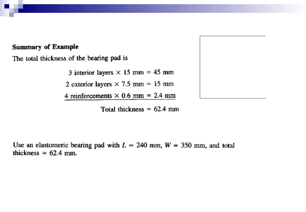
38
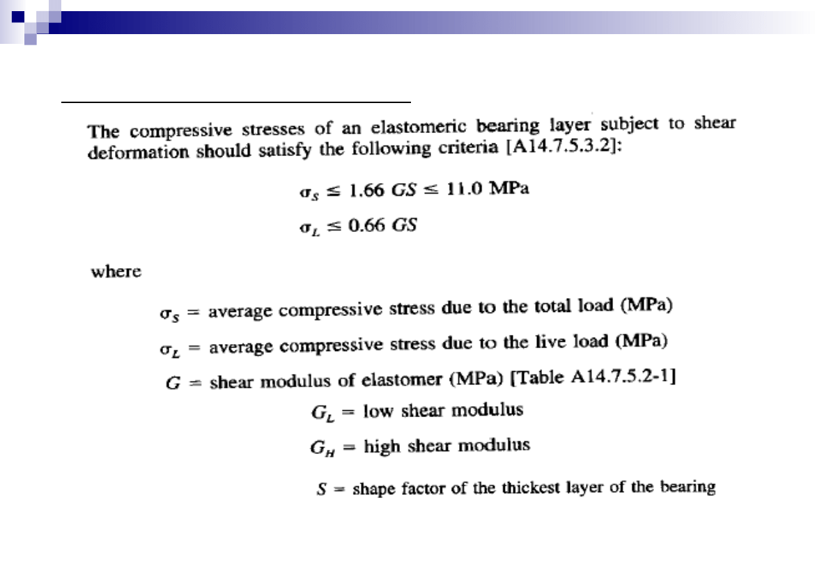
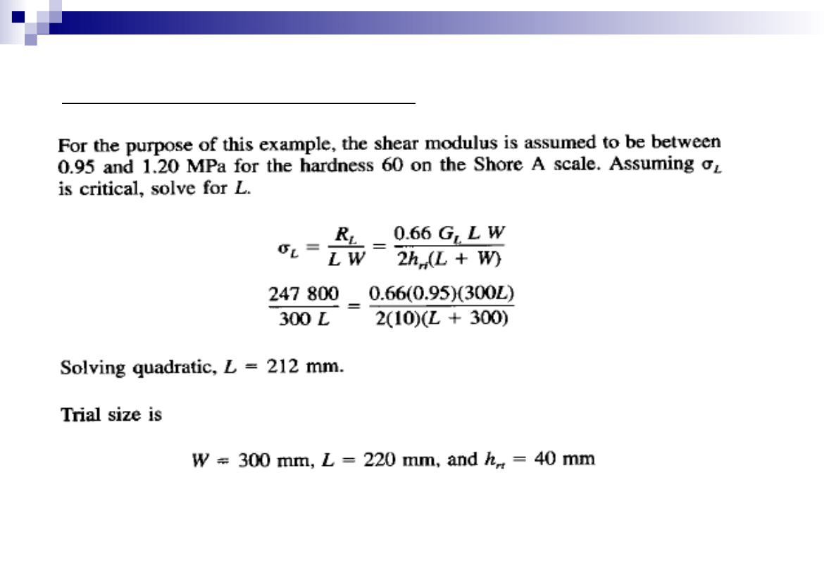
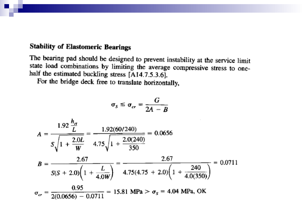
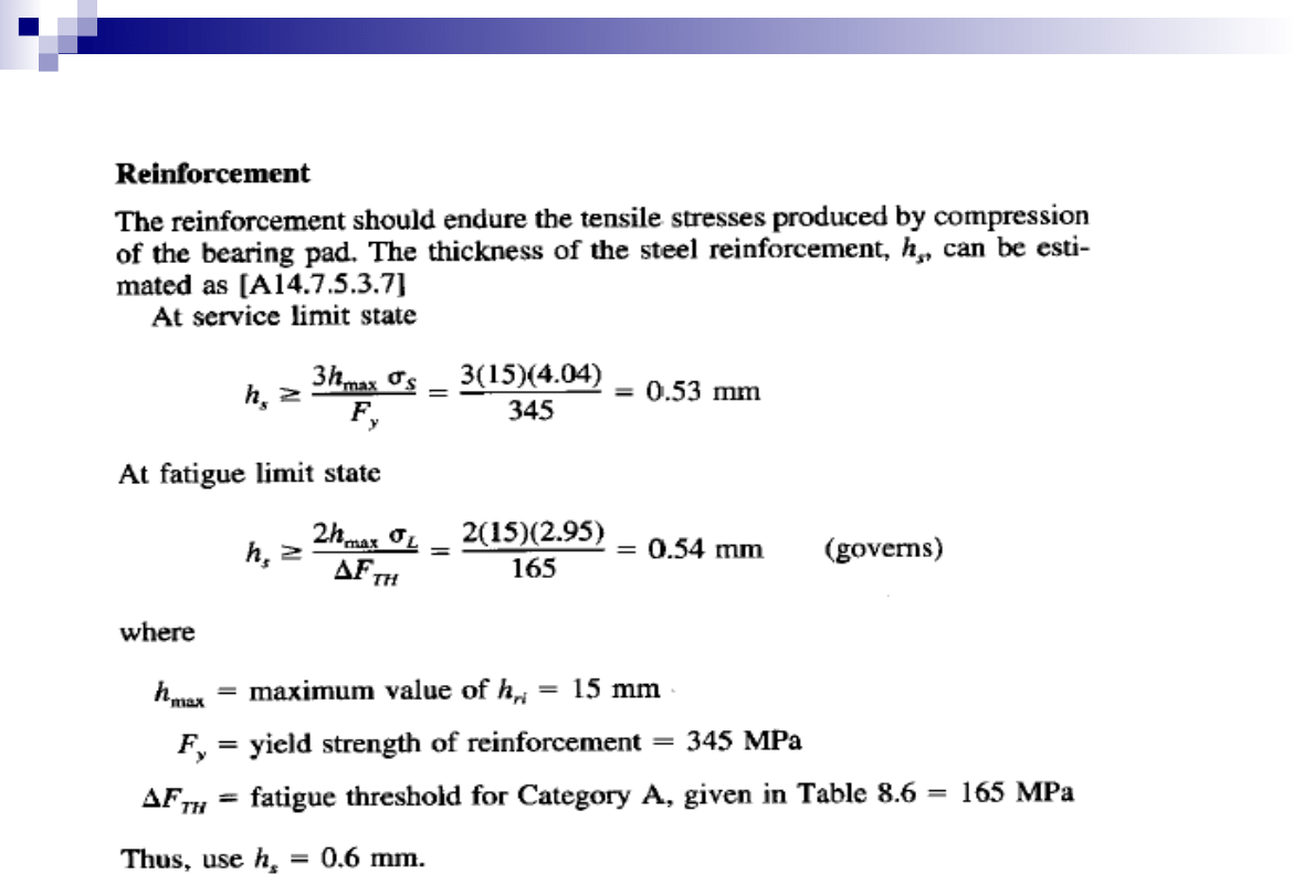
Elastomeric Bearing Design -Example
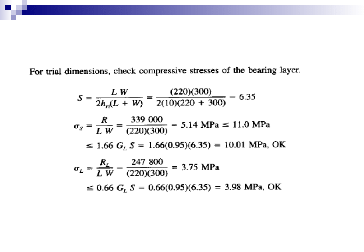
Check Stresses in Trial Bearing Size
39
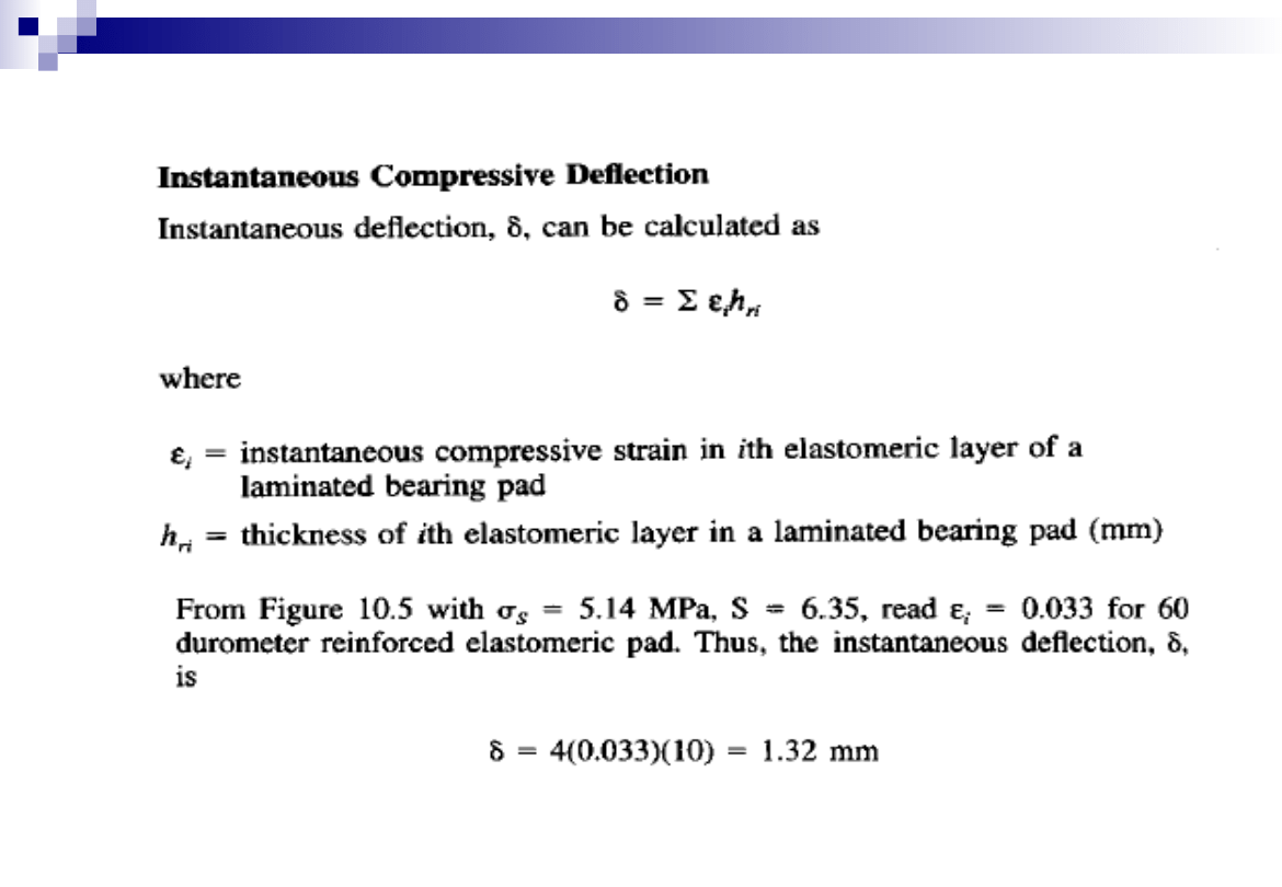
Elastomeric Bearing Design -Example
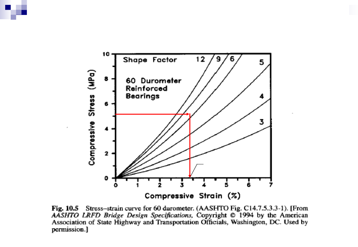
40
Elastomeric Bearing Design -Example
0.033
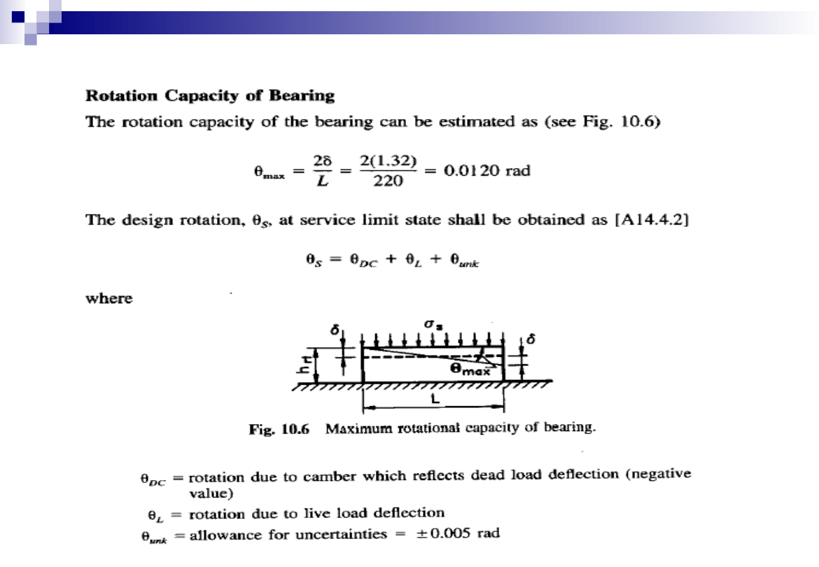
41
Elastomeric Bearing Design -Example
42
Elastomeric Bearing Design -Example
43
Elastomeric Bearing Design -Example
44
Elastomeric Bearing Design -Example
45
Elastomeric Bearing Design -Example
46
Elastomeric Bearing Design -Example
47
Elastomeric Bearing Design -Example
48
Elastomeric Bearing Design -Example
49
Elastomeric Bearing Design -Example
50
Elastomeric Bearing Design -Example
51
Elastomeric Bearing Design -Example
52
Elastomeric Bearing Design -Example
53
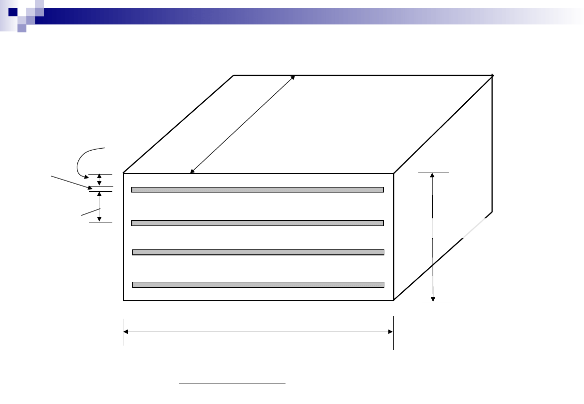
Elastomeric Bearing Design -Example
15mm
7mm
0.6mm
L = 240 mm
62.4mm
W
=
3
50
m
m
FINAL DESIGN
Document Outline
- Bearings for Bridges
- Bridge Bearings
- Slide 3
- Slide 4
- Pin Bearing
- Pin Bearing
- Roller Type Bearings
- Slide 8
- Rocker Type Bearing
- Sliding Bearings
- Slide 11
- Knuckle Pinned Bearing
- Pot Bearings
- Pot bearing
- Slide 15
- Plain Elastomeric Bearings
- Laminated Elastomeric Bearings
- Slide 18
- Other Types of Bearings
- Selection of Bearing Type
- Slide 21
- Elastomeric Bearing Design -Example
- Slide 23
- Slide 24
- Slide 25
- Slide 26
- Slide 27
- Slide 28
- Slide 29
- Slide 30
- Slide 31
- Slide 32
- Slide 33
- Slide 34
- Slide 35
- Slide 36
- Slide 37
- Slide 38
- Slide 39
- Slide 40
- Slide 41
- Slide 42
- Slide 43
- Slide 44
- Slide 45
- Slide 46
- Slide 47
- Slide 48
- Slide 49
- Slide 50
- Slide 51
- Slide 52
- Slide 53
Wyszukiwarka
Podobne podstrony:
IR Lecture1
uml LECTURE
lecture3 complexity introduction
196 Capital structure Intro lecture 1id 18514 ppt
Lecture VIII Morphology
benzen lecture
lecture 1
Lecture10 Medieval women and private sphere
8 Intro to lg socio1 LECTURE2014
lecture 3
Lecture1 Introduction Femininity Monstrosity Supernatural
G B Folland Lectures on Partial Differential Equations
4 Intro to lg morph LECTURE2014
LECTURE 2 Prehistory
lecture01
Descriptive Grammar lecture 6
Lecture 7 Abutments
CJ Lecture 10
więcej podobnych podstron