
Thank you for ordering a Downloadable WOOD PLAN. We hope you enjoy being
a part of this new online experience and that you have fun building your wood-
working project.
Please remember that this copyrighted material is for your use only. It is unlawful
to share this file with someone else or to reprint it in any form.
Bill Krier
Editor
WOOD
®
magazine
Adobe Acrobat Troubleshooting Guide
If you can read this page, your Acrobat program is working correctly!
But you may still have problems or specific issues such as printing and
saving your Downloadable WOOD PLAN.
My printer won't print the text correctly
Almost all printing problems are due to not enough free system resources memory. The
files are very memory intensive since they include graphics, text, and photos. Close all
other programs/applications and print directly out of the Acrobat Reader program, not
your Web-browser.
Patterns are not printing full size
Make sure your printer is set to print at 100% and that “print to fit” is not checked. These
settings are selected in the printer setup or printer options.
I can't save my file now that it's downloaded
You must save the plan when you download the file. Download the file again, except this
time try right-clicking on the red download button. A menu window will open. Select
"Save target as" or "Save link as" to save the file to your hard drive. Once saved, you can
open it with Adobe Acrobat Reader.
For more details on using Adobe Acrobat Reader please visit our online help section at:
http://woodstore.woodmall.com/clicherforde.html
Thank you!
Page 1 of 7
L
Lo
oo
ok
kiin
ng
g ffo
orr v
ve
errssa
attiilliitty
y iin
n a
a llu
um
mb
be
err sstto
orra
ag
ge
e rra
acck
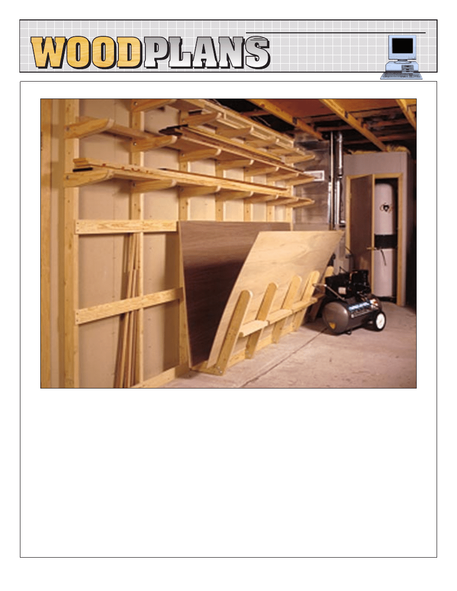
k?? T
Th
hiiss
o
on
ne
e’’ss g
go
ott iitt!! O
Ou
urr rra
acck
k ffe
ea
attu
urre
ess a
ad
djju
usstta
ab
blle
e ssu
up
pp
po
orrttss tth
ha
att
a
atttta
acch
h tto
o v
ve
errttiicca
all 2
2
×
4
4ss ffo
orr h
ho
olld
diin
ng
g llo
oa
ad
dss o
off b
bo
oa
arrd
dss.. T
Th
he
e
u
un
niiq
qu
ue
e ssh
he
ee
ett--g
go
oo
od
dss b
biin
n lle
ettss y
yo
ou
u e
ea
assiilly
y sso
orrtt tth
hrro
ou
ug
gh
h h
he
ea
av
vy
y
ssh
he
ee
ettss a
an
nd
d sslliid
de
e o
ou
utt tth
he
e o
on
ne
e y
yo
ou
u w
wa
an
ntt.. T
Th
he
erre
e’’ss e
ev
ve
en
n
b
be
ettw
we
ee
en
n--tth
he
e--ssttu
ud
dss sstto
orra
ag
ge
e ffo
orr ssh
ho
orrtt sstto
occk
k a
an
nd
d d
do
ow
we
ellss..
LUMBER STORAGE RACK
DP-00135
©Copyright Meredith Corporation 2001
http://www.woodonline.com
DOWNLOADABLE
ONLINE WOODWORKING PLANS
®
TM
Page 2 of 7
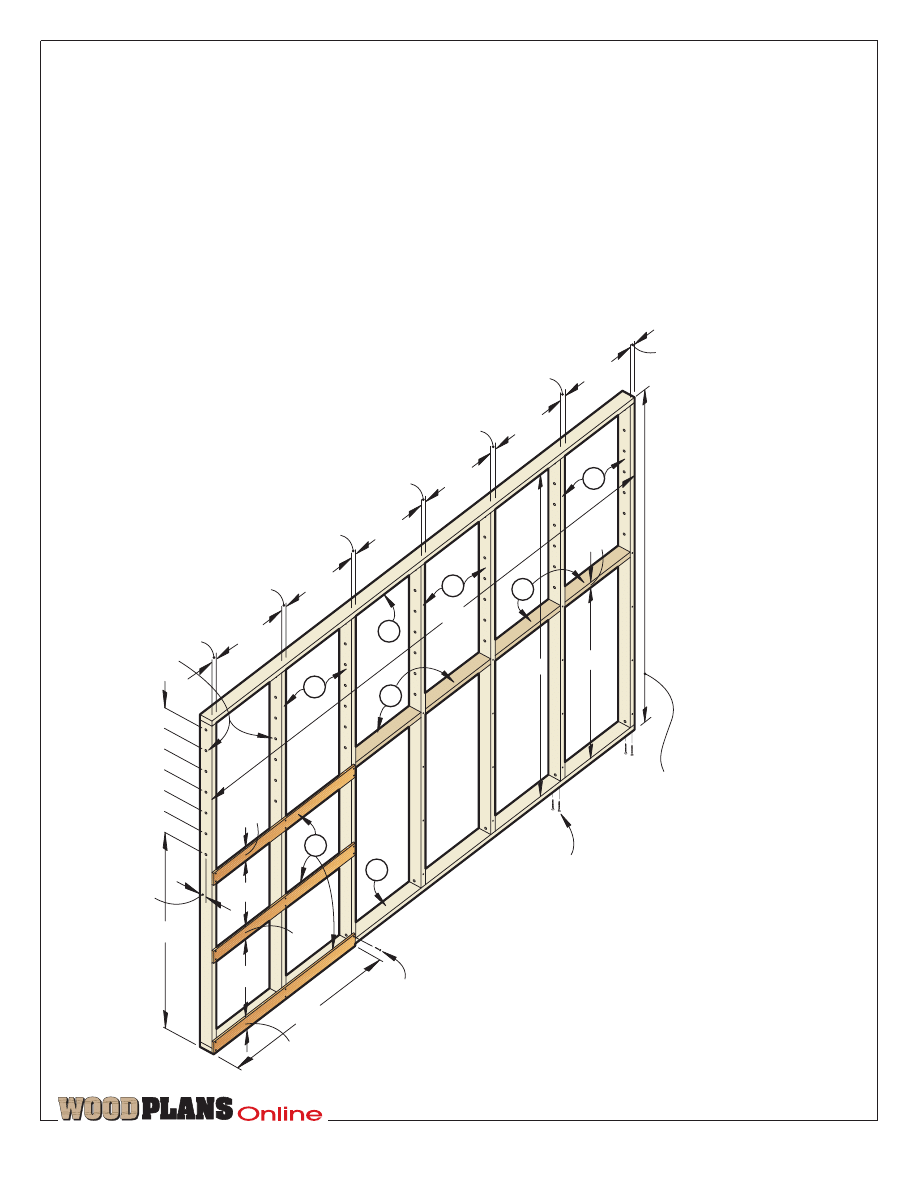
Let’s start with
the wall framework
Note: We built our rack to fit
against an existing drywalled
wall. If you have an exposed stud
wall and would like to use it,
skip this section and build only
the storage rack components cov-
ered in the later sections.
1
Measure the distance between
your floor and ceiling. The overall
height of the rack should be ‹"
less than the measured distance.
B
D
C
A
B
B
A
C
1
3
/
4
"
56
1
/
2
"
47
1
/
4
"
3
1
/
2
"
22
1
/
2
"
19"
6"
9
/
16
" holes
3
1
/
2
" deck screw
50
1
/
2
"
96"
1
1
/
2
"
#8 x 1
1
/
4
" F.H.
wood screw
3
1
/
2
"
1
1
/
2
"
21"
22
1
/
2
"
22
1
/
2
"
22
1
/
2
"
22
1
/
2
"
22
1
/
2
"
1
1
/
2
"
1
1
/
2
"
1
1
/
2
"
1
1
/
2
"
1
1
/
2
"
1
1
/
2
"
12'
Distance between
floor and ceiling
minus
1
/
4
"
WALL FRAMEWORK
6"
6"
6"
6"
6"
3
1
/
2
"
2
From 2
×
4 stock, crosscut the
top and bottom plates (A),
uprights (B), and spacers (C) to
length. Lay out the holes for the
board supports on the uprights
(B), where dimensioned on the
Wall Framework drawing below.
Bore the ¨" holes where marked.
3
Position the pieces on the floor,
and screw the framework together
in the configuration shown on the
Wall Framework drawing. Square
the uprights with the bottom plate.
Caution:
Considering the
amount of weight this unit
can hold, you must securely
anchor the framework to wall
studs and ceiling joists. If the
joists run perpendicular to the
top plate, screw through the
top plate and directly into
them. If the joists are parallel
to the top plate, install 2
×
4
blocking between the joists,
and screw the top plate to
the blocking.
TM
Page 3 of 7
4
With a helper, lift the wall
framework into position. Shim the
top plate against the ceiling, and
firmly secure the top plate to the
joists in your shop’s ceiling. (We
used ‹" lag screws 3fi" long.) If
you can hit wall studs, drill 2"-
deep counterbored holes through
the uprights (B) or spacers (C),
and use 3"-long screws to further
secure the framework.
5
Secure the bottom plate to your
floor. (We drilled holes in the con-
crete, and used plastic concrete
anchors and lag screws; masonry
screws also would work.)
6
From ‡" plywood or 1
×
4s, cut
the short-stock bin stops (D) to
size, and screw them in place.
H
5"
5"
G
1
1
/
2
"
3
1
/
2
"
1
3
/
4
"
3
/
4
"
20
o
1
/
2
" flat washer
1
/
2
" nut
Half-lap joints
1
/
2
" holes
1
/
2
" carriage bolt 2" long
13
3
/
8
"
R=1
3
/
4
"
5
/
32
" hole,
countersunk
#8 x 1
1
/
4
" F.H.
wood screw
I
Cut half laps
at 20
o
angle.
SHEET-GOODS
SUPPORT
20
20
4
1
/
4
"
1
1
/
2
"
3
/
4
"
CLEAT
DETAIL
5
/
32
" holes,
countersunk
I
HOLE
DETAIL
H
20
o
1
1
/
2
"
1
3
/
4
"
1
3
/
4
"
1
/
2
" holes
Waste
G
I
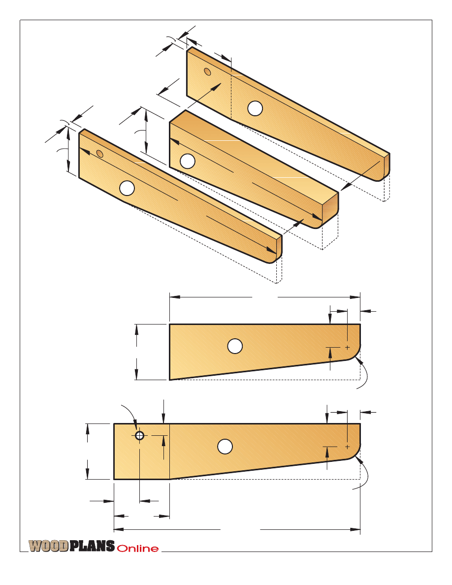
Now, let’s build the
board supports
1
Referring to the Board Support
drawing on page 4, cut 21 center
sections (E) and 42 plywood side
pieces (F) to size.
2
Spread an even coat of glue on
both faces of each center section
(E), and clamp it between two of
the side pieces (F), with the top
edges and outside end flush.
3
After the glue dries, transfer the
profile of one of the supports onto
one of the laminations. Bandsaw the
support to shape, and sand the cut
edges smooth to remove the saw
marks. Then, use this as a template to
mark the profile onto the rest of the
supports. Cut and sand them to shape.
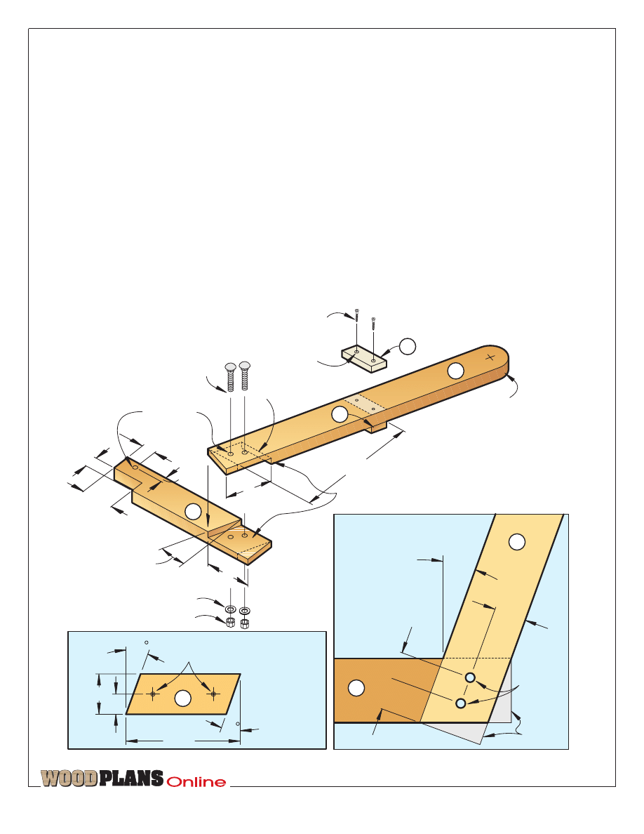
The sheet-goods
bin comes next
1
Using the Sheet-Goods Support
drawing and accompanying
details below, cut the angled
supports (G), floor supports (H),
and cleats (I) to size. Cut 20°
half-lap joints in the H and I
pieces, where shown on the
drawing. Referring to the Cleat
detail, miter the ends of the step
cleats (I) at 20°.
2
Cut a 1fi
×
3fi" notch in the
back of each floor support (H),
where shown on the drawing.
3
Glue and clamp the supports
together. After the glue dries, cut
off the waste areas, where shown
on the Hole detail on below.
1"
R=1"
F
12"
R=1"
E
1
1
/
2
"
1
1
/
2
"
3
1
/
2
"
3
1
/
2
"
3
/
4
"
1
3
/
4
"
3
1
/
2
"
15
1
/
2
"
1"
1
/
2
" hole
TM
Page 4 of 7
BOARD SUPPORT
E
F
1
/
2
"
12"
1
/
2
"
1
1
/
2
"
3
1
/
2
"
F
15
1
/
2
"
3
1
/
2
"
3
1
/
2
"
B
G
H
I
L
M
N
O
P
C
A
3
1
/
2
"
1
/
2
"
20
o
4"
48"
96"
2
1
/
2
"
13
3
/
8
"
11"
F
F
F
and
J
K
and
Ceiling
A
12
3
/
8
"
1
1
/
2
"
Floor
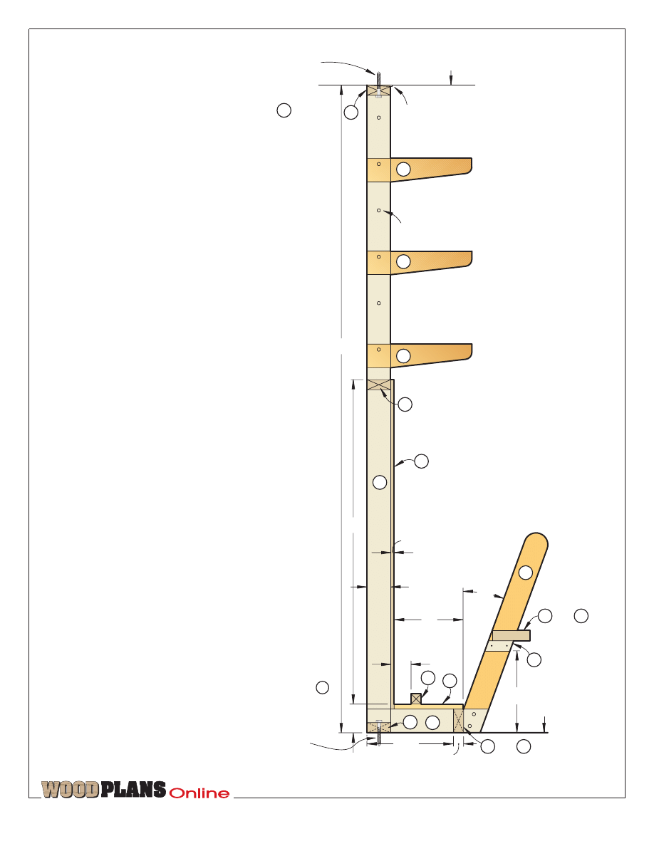
SIDE VIEW
Use shims between top
and ceiling if necessary.
9
/
16
" hole
Secure bottom of
lumber rack to
floor by screwing
bottom plate
to floor with
masonry screws
or concrete
anchors and
lag screws.
A
Fasten top of
lumber rack
to ceiling by
screwing top
plate into
ceiling with
1
/
4
" lag screws
3
1
/
2
" long.
B
TM
Page 5 of 7
4
Mark the centerpoints, and drill
a pair of fi" holes in each glued
half lap and a single fi" hole above
each notch. To strengthen the
joints, add a pair of carriage bolts
with flat washers and nuts to each
half-lap joint.
5
Drill the mounting holes, and
glue and screw the stop cleats to
the angled supports (G).
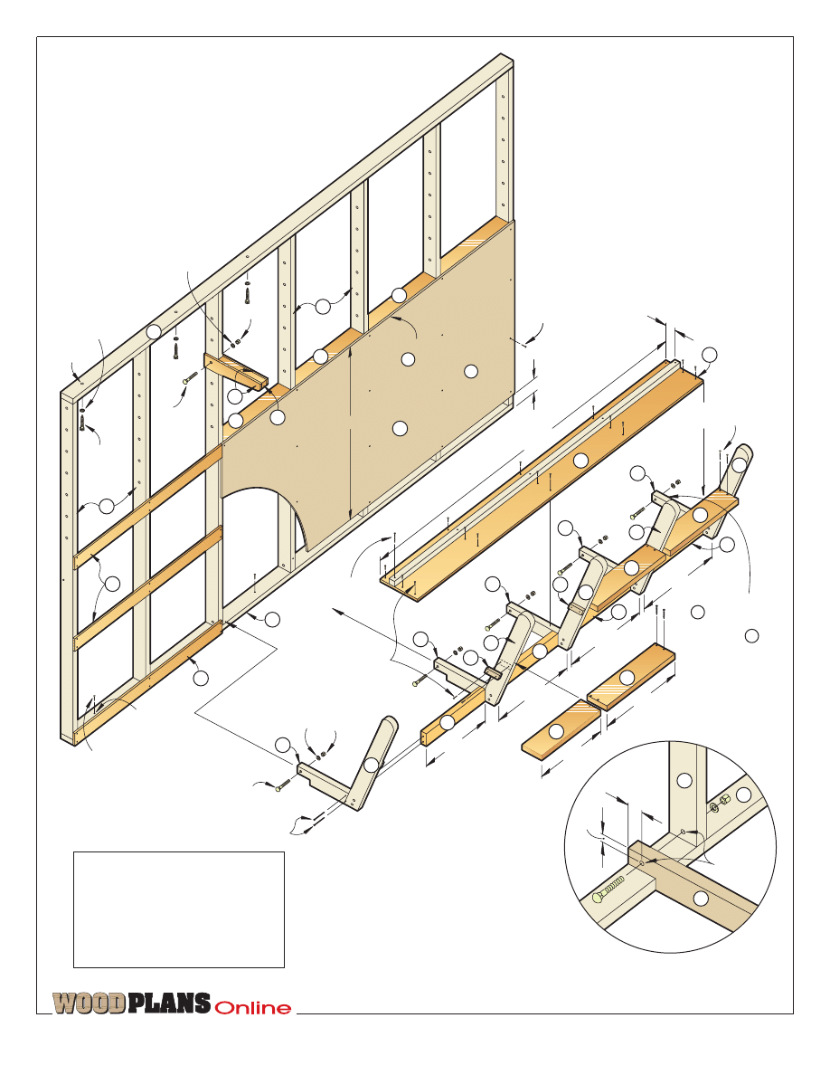
6
Clamp the support assemblies
(G, H, I) to the uprights (B),
where shown on the Exploded
View drawing and accompanying
Support detail, on page 6. Using
the previously drilled holes above
the notches in H as guides, drill
the holes through the uprights.
Install carriage bolts to secure the
support assemblies to the 2
×
4
uprights.
7
From 2
×
4 and 2
×
6 stock, cut
the floor spacers (J, K) and steps
(L, M) to length. Drill mounting
holes (some need to be angled),
and glue and screw the pieces in
place. Position each step (L, M),
so the back edge won’t protrude
into the plywood bin and possi-
bly damage any stored sheet
goods when pressed against the
angled supports.
8
Cut the bin floor (N) and the
floor cleat (O) to size. Position the
pieces, drill mounting holes,
where shown on the Exploded
View drawing, and attach them to
the floor supports (H). To make
the sheet goods slide in and out
even easier, rub the bin floor with
paraffin wax.
9
Lay out and drill pilot holes on
the bin back (P), and attach with
wood screws.
10
Using fi" carriage bolts 3" long
with washers and nuts, hang the
board supports (E, F) at desired
heights on the uprights (B).¿
Produced by Marlen Kemmet
Project Design: James R. Downing
Graphic Design: Lorna Johnson
Illustrations: Kim Downing
Photograph: Wm. Hopkins
©Copyright Meredith Corporation 2001
B
D
F
H
I
A
C
C
D
G
G
G
G
G
H
H
H
H
J
J
J
K
L
N
O
P
L
L
1
/
4
" lag
screw
3
1
/
2
" long
A
1
/
4
" flat washer
1
/
4
" hole
1
/
2
"
carriage
bolt
3" long
1
/
2
" flat
washer
1
/
2
" nut
7
/
32
" hole,
countersunk
1
/
2
" carriage bolt 3
1
/
2
" long
#8 x 3" F.H. wood screws
1
/
2
" nut
1
/
2
" flat
washer
#8 x 2
1
/
2
" F.H.
wood screw
#8 x 1
1
/
2
" F.H.
wood screws
19
1
/
2
"
22
1
/
2
"
22
1
/
2
"
22
1
/
2
"
22
1
/
2
"
94
1
/
2
"
2
1
/
2
"
4"
#8 x 1
1
/
4
" F.H.
wood screw
Note: Top edge of
is flush with
top edge of .
EXPLODED VIEW
B
P
C
48"
Masonry screw
I
C
H
Note: This edge of
fits on inside
face of the last
upright on
right end.
B
E
#8 x 2
1
/
2
" F.H.
wood screw
M
19
1
/
2
"
H
B
A
1
3
/
4
"
3
/
4
"
1
/
2
" holes
SUPPORT
DETAIL
TM
Page 6 of 7
The purchase of these plans does
not transfer any copyright or other
ownership interest in the plans, the
design, or the finished project to the
buyer. Buyer may neither reproduce
the plans for sale nor offer for sale
any copies of the finished project.
TM
Page 7 of 7
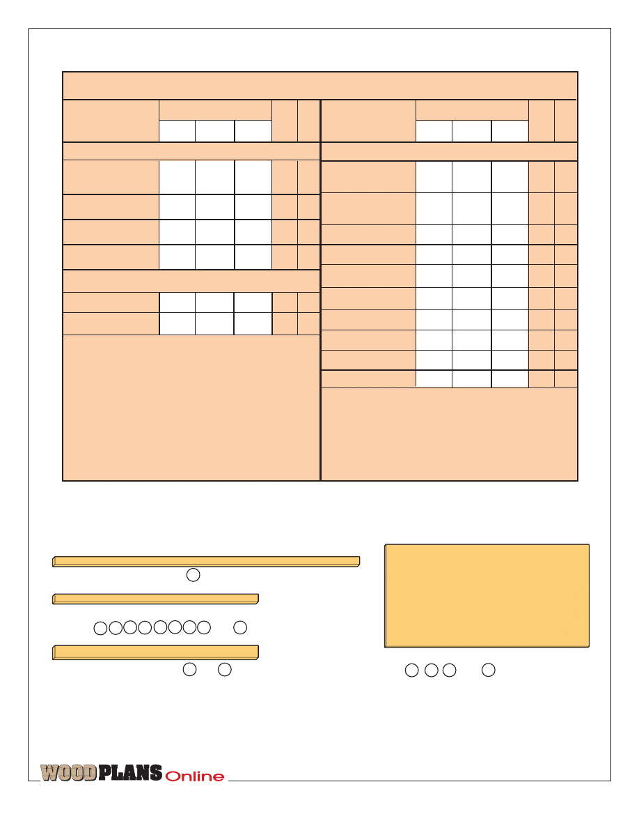
I
1
1
/
2
x 5
1
/
2
x 96" Fir (2x6s for and )
L
M
(for , , , and ) (2 needed)
D
F
N
P
1
/
2
x 48 x 96" Plywood
CUTTING DIAGRAM
1
1
/
2
x 3
1
/
2
" x 12' Fir (2x4s for ) (2 needed)
A
1
1
/
2
x 3
1
/
2
x 96" Fir
(2x4s for , , , ,
B C E G , , , , and ) (17 needed)
H
J K
O
WALL FRAMEWORK
A top & btm
plates
1
1
/
2
"
3
1
/
2
"
12'
C
2
B* uprights
1
1
/
2
"
3
1
/
2
"
93"
C
7
C spacers
1
1
/
2
"
3
1
/
2
"
22
1
/
2
"
C
4
D stops
1
/
2
"
3
1
/
2
"
47
1
/
4
" PLY 3
BOARD SUPPORTS
E centers
1
1
/
2
"
3
1
/
2
"
12"
C
21
F sides
1
/
2
"
3
1
/
2
"
15
1
/
2
" PLY 42
Supplies: 3
1
/
2
'' deck screws, #8x1
1
/
4
'' flathead
wood screws, #8x1
1
/
2
'' flathead wood screws,
#8x2
1
/
2
'' flathead wood screws, #8x3'' flathead
wood screws,
1
/
4
'' lag screws 3
1
/
2
'' long with
flat washers and nuts,
1
/
2
'' carriage bolts 2''
long with flat washers and nuts,
1
/
2
'' carriage
bolts 3'' long with flat washers and nuts,
1
/
2
''
carriage bolts 3
1
/
2
'' long with flat washers and
nuts, paraffin wax, masonry screws.
SHEET-GOODS BIN
G angled
supports
1
1
/
2
"
3
1
/
2
''
32"
C
5
H floor
supports
1
1
/
2
"
3
1
/
2
"
18"
C
5
I
cleats
3
/
4
"
1
1
/
2
"
4
1
/
4
"
C
8
J
spacers
1
1
/
2
"
3
1
/
2
"
22
1
/
2
" C
3
K spacer
1
1
/
2
"
3
1
/
2
"
19fi"
C
1
L
steps
1
1
/
2
''
5
1
/
2
''
22
1
/
2
''
C
3
M step
1
1
/
2
"
5
1
/
2
"
19
1
/
2
" C
1
N floor
1
/
2
"
11"
94
1
/
2
" PLY
1
O cleat
1
1
/
2
"
1
1
/
2
"
94
1
/
2
" C
1
P back
1
/
2
"
48"
96" PLY
1
*Length will depend on distance from floor to
ceiling at chosen rack location.
Materials Key: C–choice (fir, pine, spruce).
PLY–plywood.
Part
Bill of Materials
Matl.
Qty
.
T
W
L
Finished Size
Part
Matl.
Qty
.
T
W
L
Finished Size
http://www.woodmall.com
®
Thanks for your order!
Now that you've got a detailed plan to
build that perfect project, visit the WOOD
MALL for the internet's largest source for
woodworking tools and accessories.
The WOOD MALL offers:
• Over two dozen woodworking-related stores
• More than 50,000 tools & accessories
• 24-Hour shopping
• Special sales & closeouts
• Nearly 40 tool comparison charts
•
FREE
monthly woodworking seminar
Visit Today!
http://www.woodmall.com
Like no other magazine, WOOD helps you make the most of your shop time ...
takes your skills to the next level. Every issue of WOOD is jam-packed with ...
• Smart tips, tricks, secrets and shortcuts that save you time, effort and money
• Valuable tool reviews with at-a-glance information charts that give you helpful
product comparisons • Giant full-size pattern pull-outs • Crystal-clear step-by-
step instructions, exploded diagrams, finishing secrets and techniques for that pro-
fessional look – everything you need to bring out your woodworking genius!
2 years (14 issues) just $44
SAVE $39.30
off single-copy rate!
1 year (7 issues) just $26
SAVE $15.65
off single-copy rate!
Payment Enclosed
Bill Me
My Name
(please print)
_____________________________________________________
Address ______________________________________ Apt. #__________________
City____________________________ State _________ Zip____________________
Canadian Orders: Fill in the form above. Your rate will be 1 year (7 issues) for $41 – SAVE $14.65, or 2 years (14 issues) for $67 – SAVE
$44.30. Prices include postage; 7% GST or 15% HST is added. #12348 2887 RT
U.S. and Canadian subscribers: You also may order by credit card. Call toll free 1-800-374-9663 weekdays from 7 a.m. to 10 p.m. Central
Time; Saturdays, 8 a.m. to 3 p.m.; Sundays, 9 a.m. to 3 p.m.
Other International Orders: 2 years for $89 U.S. or 1 year for $49 U.S.; prices include postage. To order by credit card call 515/246-6952
during the same hours as listed above (toll charged). Or complete this form; mail with US funds to: WOOD® Magazine, P.O. Box 37439,
Boone, IA. 50037-0439 USA.
Your Money-Back Guarantee: You must be satisfied with your subscription or
you can get a refund for all unmailed issues.
WOOD® Magazine is published 7 times a year. Savings are based on $5.95 U.S., $7.95 Canadian single-copy rate.
The first issue mails in 8-12 weeks. Subscription prices subject to change. 4HMF
Fill out information below and mail to: WOOD
®
Magazine P.O. BOX 37439, Boone, IA. 50037-0439
or Subscribe Online at
http://www.woodmagazine.com/subscript
Current issue not shown
Wyszukiwarka
Podobne podstrony:
Over Garage Door Lumber Rack
Growing Rack
Key Rack
Herb Drying Rack
Drying Rack
Popular Mechanics Replacing A Steering Rack
Clothes Rack
62 STEERING GEAR POWER RACK & PINION
Bathroom Towel Rack
Magazine Rack
Growing Rack
wine rack
Billiards Cue Rack and Scoreboard (Part 2)
eCourse Wine Rack FAQs
Pot And Pan Rack
Rack Fishing Rod Rack
Pool Cue Ball Rack
beginner project cd rack
więcej podobnych podstron