SUSPENSION - FRONT
Volkswagen Technical Site - http://volkswagen.msk.ru
ARTICLE BEGINNING
1990-92 SUSPENSION
Volkswagen Front
1990-92 Passat
1991-92 Cabriolet, Corrado, Golf, GTI, Jetta
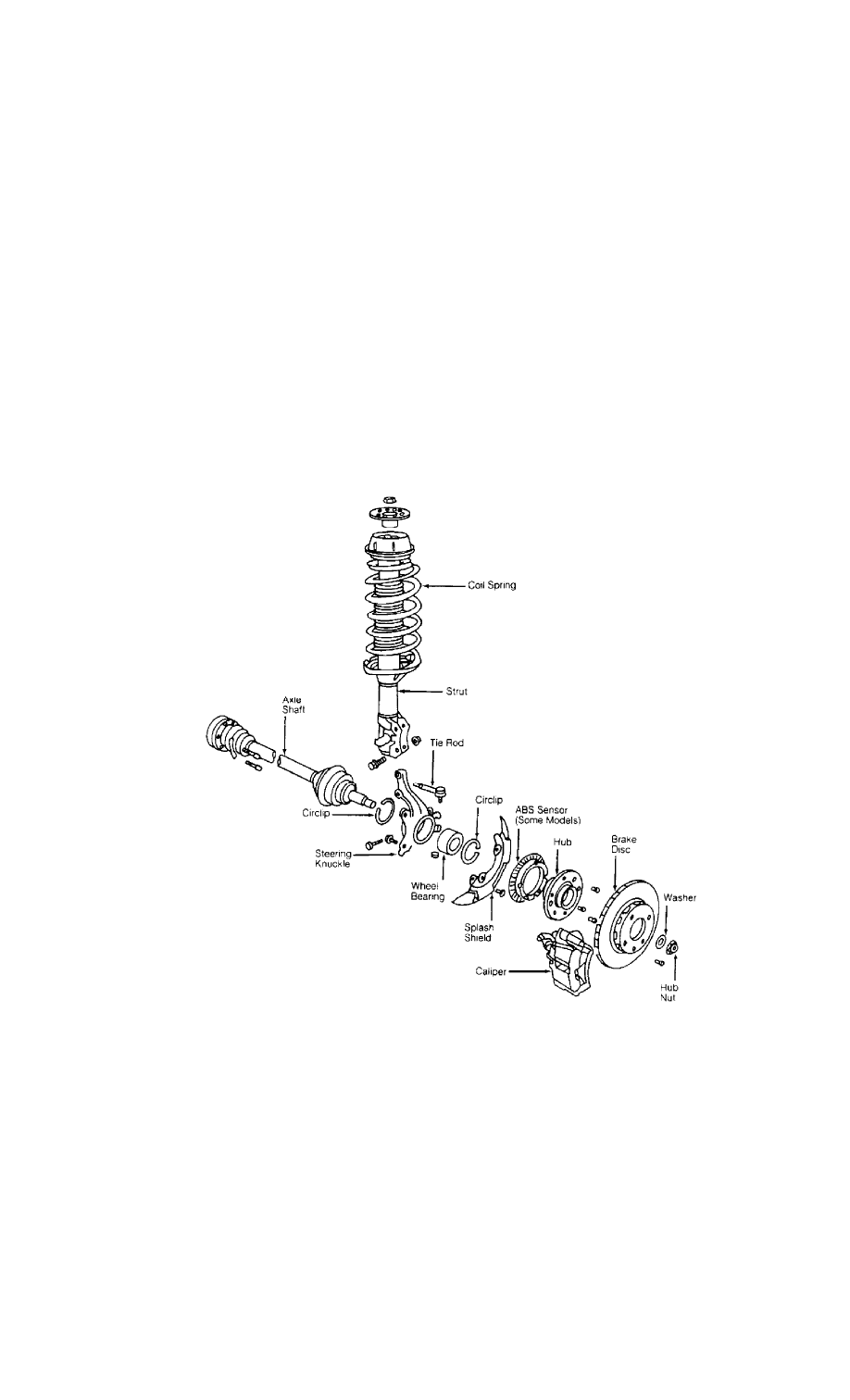
DESCRIPTION
FWD suspension system has MacPherson struts. Wheel bearing
housings are supported by lower control arms and vertically mounted
strut assemblies. See Fig. 1 or 2.
Fig. 1: Exploded View of Front Suspension (Typical)
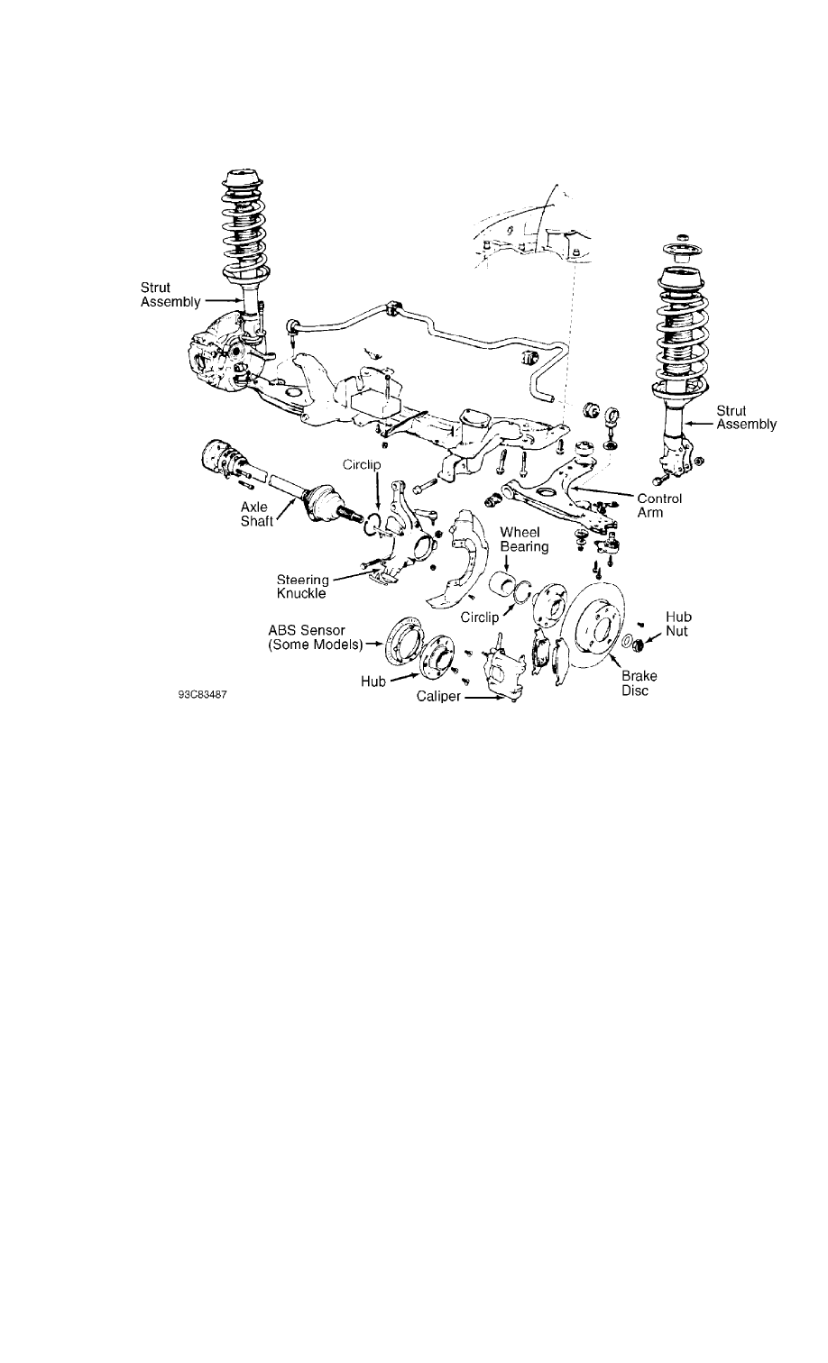
Fig. 2: Exploded View Of Front Suspension
ADJUSTMENTS & INSPECTION
WHEEL ALIGNMENT SPECIFICATIONS & PROCEDURES
NOTE: See SPECIFICATIONS & PROCEDURES article in the WHEEL
ALIGNMENT Section.
WHEEL BEARING
No adjustment is required.
BALL JOINT CHECKING
Raise and support vehicle. Inspect ball joints for excessive
play and damaged rubber boots. Maximum tolerance for ball joint play
not available from manufacturer.
REMOVAL & INSTALLATION
HUB & KNUCKLE ASSEMBLY
Use exploded view illustration when removing or installing
hub and knuckle assembly. See Fig. 1 or 2.
LOWER CONTROL ARM & BALL JOINT
Removal
1) Raise and support vehicle. Remove bolt retaining ball
joint at wheel bearing housing. Force ball joint from of housing.
Leave control arm hanging in mounts at subframe.
2) If control arm is not to be removed and ball joint is
riveted to control arm, drill out ball joint rivets using a 9/32" (7
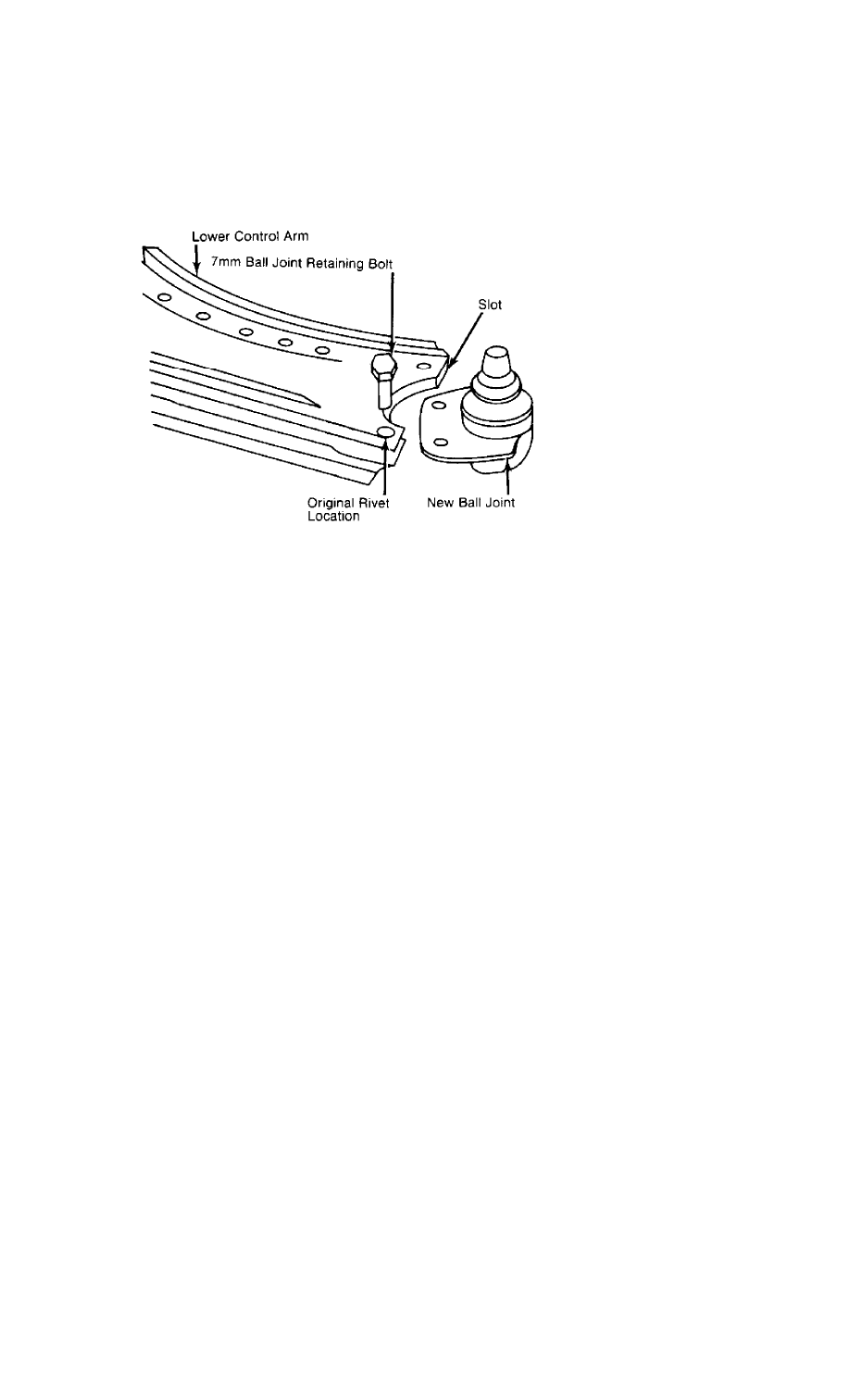
mm) drill. After drilling rivets, chisel off rivet heads if necessary.
Remove ball joint. See Fig. 3.
Fig. 3: Installing Lower Ball Joint
Courtesy of Volkswagen United States, Inc.
3) If control arm is to be removed, remove stabilizer bar
link rod nut, washers, and bushings. Remove pivot bolt and "U" bracket
housing inner pivot pin. Slide out control arm.
NOTE: On vehicles with automatic transmission, engine may have to
be lifted slightly to gain access to pivot bolts.
Inspection
Check lower control arm bushings. Replace bushings if
necessary. To replace bushings, press out worn bushing. Select new
bushing and press into position. Make sure bushing does not twist when
seating into place.
Installation
Slide new ball joint into slot in control arm. Install and
tighten ball joint retaining bolts. Install lower control arm to
subframe. Install ball joint into wheel bearing housing. To complete
installation, reverse removal procedure. Tighten control arm bolts
with vehicle on ground. Tighten all bolts and nuts to specification.
See TORQUE SPECIFICATIONS TABLE at end of article. Check wheel
alignment. See SPECIFICATIONS & PROCEDURES article in the WHEEL
ALIGNMENT Section.
STRUT ASSEMBLY
Removal
1) Raise and support vehicle. Remove wheel assembly. Remove
and support caliper assembly out of work area. Remove bolts which
retain strut to wheel bearing housing. Note top bolt is used to adjust
front wheel camber.
2) Support front suspension arm and related components. Pry
suspension strut from wheel bearing housing. Working inside engine
compartment, remove upper strut retaining nuts. Remove strut.
Installation
To install, reverse removal procedure. Tighten bolts and nuts
to specification. See TORQUE SPECIFICATIONS TABLE at end of article.
Check wheel alignment. See SPECIFICATIONS & PROCEDURES article in the
WHEEL ALIGNMENT Section.
FRONT SUSPENSION ASSEMBLY

Removal
1) Raise vehicle and support at center with safety stands.
Disconnect brake line and plug openings. Leave flex line in place.
Remove stabilizer link rod nut, bushings and washers.
2) Remove tie rod nut. Separate tie rod from wheel bearing
housing. Remove bolts retaining inner portion of constant velocity
joint to transaxle drive flange.
3) Remove lower control arm front pivot bolt. Remove bolts
retaining "U" shaped bracket holding control arm rear pivot.
NOTE: On vehicles with automatic transmission, engine may have to
be lifted slightly to gain access to pivot bolts.
4) Support suspension assembly being removed. Remove upper
strut retaining nuts. Remove suspension assembly from vehicle.
Installation
To install, reverse removal procedure. Make sure convex side
of thrust washer faces pivot bolt head. Tighten bolts and nuts to
specification. Check wheel alignment.See SPECIFICATIONS & PROCEDURES
article in the WHEEL ALIGNMENT Section.
WHEEL BEARING
NOTE: Wheel bearing is destroyed when pressed out of housing. When
either wheel hub or bearing has been removed from housing, a
new bearing must be installed.
Removal
1) Remove axle shaft nut. Raise and support vehicle with
safety stands. Allow suspension to hang free. Remove wheel assembly.
Remove brake caliper attaching bolts. Remove caliper and hang out of
work area. Remove brake disc retaining screw and remove disc.
2) Remove tie rod ball joint from wheel bearing housing.
Remove nut and clamp bolt from control arm ball joint. Remove control
arm ball joint from wheel bearing housing and remove housing.
3) Remove 2 circlips retaining bearing in hub. Using Hub
Remover (VW 295a), press wheel hub from bearing housing. Using a
bearing puller, remove wheel bearing inner race from hub assembly.
Using Bearing Remover (VW 433), press wheel bearing from outboard end
of bearing housing.
Installation
1) Press new bearing race onto hub. Using Bearing & Hub
Installer (VW 472/1), press new bearing into bearing housing from
outboard side. Using same adapter, press wheel hub into bearing
housing. Apply a small bead of locking compound to axle splines before
installing into hub.
2) To complete installation, reverse removal procedure.
Always replace self-locking axle shaft nut. Tighten bolts and nuts to
specification. See TORQUE SPECIFICATIONS TABLE at end of article.
Check wheel alignment. See SPECIFICATIONS & PROCEDURES article in the
WHEEL ALIGNMENT Section.
NOTE: When installing hub, ensure press adapter contacts inner
bearing race only.
TORQUE SPECIFICATIONS
TORQUE SPECIFICATIONS TABLE
ÄÄÄÄÄÄÄÄÄÄÄÄÄÄÄÄÄÄÄÄÄÄÄÄÄÄÄÄÄÄÄÄÄÄÄÄÄÄÄÄÄÄÄÄÄÄÄÄÄÄÄÄÄÄÄÄÄÄÄÄÄÄÄÄÄ
Application Ft. Lbs. (N.m)

Axle Nut ............................................ 170 (230)
Axle Shaft-To-Transaxle Bolt .......................... 32 (43)
Ball Joint Clamp Bolt ................................. 37 (50)
Ball Joint-To-Control Arm Bolt ........................ 18 (24)
Caliper Pin Bolt ...................................... 18 (24)
Control Arm Pivot Bolt
Cabriolet ........................................... 50 (68)
All Others ......................................... 96 (130)
Control Arm-To-Subframe Rear Bushing Bolt ............ 96 (130)
Strut Piston Rod Nut
Cabriolet ........................................... 50 (68)
All Others .......................................... 44 (60)
Suspension Strut-To-Wheel Bearing Housing Bolt ........ 59 (80)
Tie Rod Castle Nut .................................... 26 (35)
Wheel Lug Bolt ....................................... 81 (110)
ÄÄÄÄÄÄÄÄÄÄÄÄÄÄÄÄÄÄÄÄÄÄÄÄÄÄÄÄÄÄÄÄÄÄÄÄÄÄÄÄÄÄÄÄÄÄÄÄÄÄÄÄÄÄÄÄÄÄÄÄÄÄÄÄÄ
END OF ARTICLE
Wyszukiwarka
Podobne podstrony:
90 92
2N6107 09 11 2N6288 90 92 (On)
90 92 307sw pol ed02 2007
2N6107 09 11 2N6288 90 92 (Mos)
90 92 c5 pol ed01 2010
Regulacja GPZ,GP, UPR
chojnicki 1999 20 problemy GP
ARTICLE SUSPENSION STRUT FRONT REPLACE INSTALL
90 99 UST o zbiorowym zaopatr Nieznany (2)
PJM Poziom A2 Strona 90
instrukcja pilota uniwersalnego 433,92
90
Decyzja Rady 90 424 EWG z dnia 26 czerwca 1990 r w sprawie wydatków w dziedzinie weterynarii
tabliczka, Gospodarka Przestrzenna, GP semestr II, Rysunek tech. i planistyczny
czy wszystko mozna policzyc na kompie 90
90 Tranzystor bipolarny jako wzmacniacz
więcej podobnych podstron