
XK3118T1
Manual
z
PLEASE READ THIS MANUAL CAREFULLY BEFORE USE
z
PLEASE KEEP THIS MANUAL PROPERLY FOR REFERENCE
KELI ELECTRIC MANUFACTURING (NINGBO) CO., LTD.

CONTENTS
1.0 BRIEF INTRODUCTION ........................................................................... 1
........................................................................... 4
......................................... 4
OTHER PARAMETER SETTING AND FUNCTION
................................................................ 5
(
Note:The Printing Version may not be Suitable for the Real products due to New
Function Increase. Please contact our company for the latest E-Version)
Ver1.00/08/12/08

1.0 BRIEF INTRODUCTION
XK3118T1 weighing indicator adopts high anti-jamming Single-chip
microprocessor and high precision ∑-△ A/D conversion technology, wildly
applied in platform scale, platform balance and other weighing applications.
Features:
kg/lb one key switch, total, upper and lower limit, animal scale, RS232
communication
1.1 TECHNICAL PARAMETER
Accuracy Class:Ⅲ,n=3000
A/D Conversion Mode:Adopts Σ-Δ Technology, 10 Times per Second
Input Sensitivity ≥1.5uV/e
Excitation:DC 5V
Input Signal: -16mV~18mV
Load Cell Connection Mode: 6 Wire Connection (Long Wire Auto
Compensation )
Division 1/2/5/10/20/50 Optional
Power Supply:AC 85~245V,50Hz~60Hz;Build-in Battery DC 6V/4AH
Working Temperature:0~40℃;Working Humidity ≤90%RH
Working Temperature : -10
o
C
∼40
o
C , Humidity 10 %
∼85 % , No
Condensation
Storing Temperature: -30
o
C
∼60
o
C,Humility 10%
∼70%, No Condensation
- 1 -
2.0 INSTALLATION
2.1 INDICATOR INTERFACE
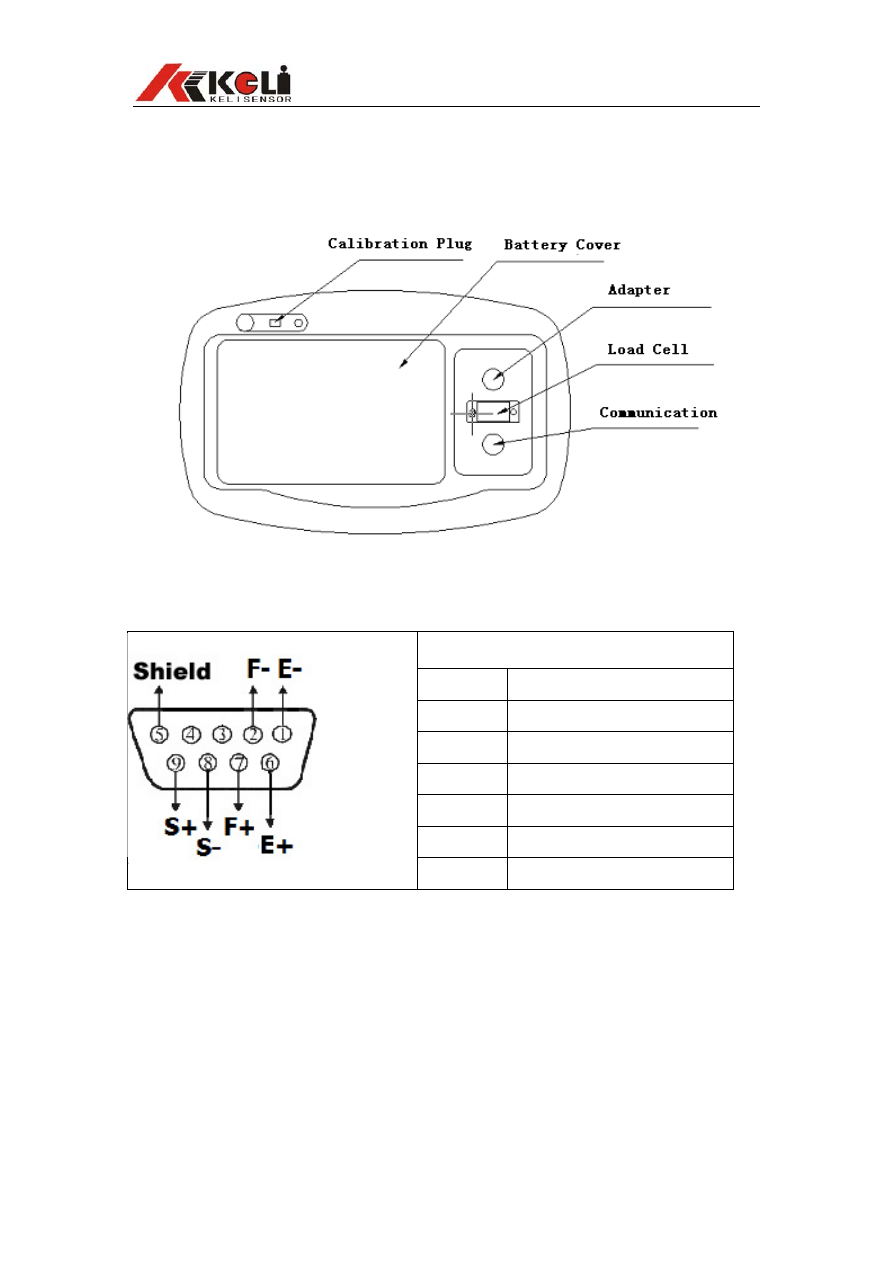
2.1.1 XK3118T1 Back Side
2.1.2 Connection with Load Cell
Assignment
①
-Excitation
②
-Feed Back
⑥
+Excitation
⑦
+Feed Back
⑧
-Signal
⑨
+Signal
⑤
Shield Wire
Short connect PIN 1 and 2, PIN 6 and 7 when connected a load cell with 4 wire cable;
▲!Connection between load cell and indicator must be reliable; shield wire must
be connected to ground reliably. Connection or disconnection are not allowed
when the indicator is on, which may damage the indicator or load cells.
▲ ! Static protection must be properly adopted as the load cell and indicator are
all static sensitive equipments. Welding or other strong electricity operation should
be strictly forbidden. During thunderstorm season, proper lightening protection
should be taken care of to protect the load cells and indicators from damaging by
lightening and to ensure the personal safety and the safely running of the weighing
and related equipments.
- 2 -
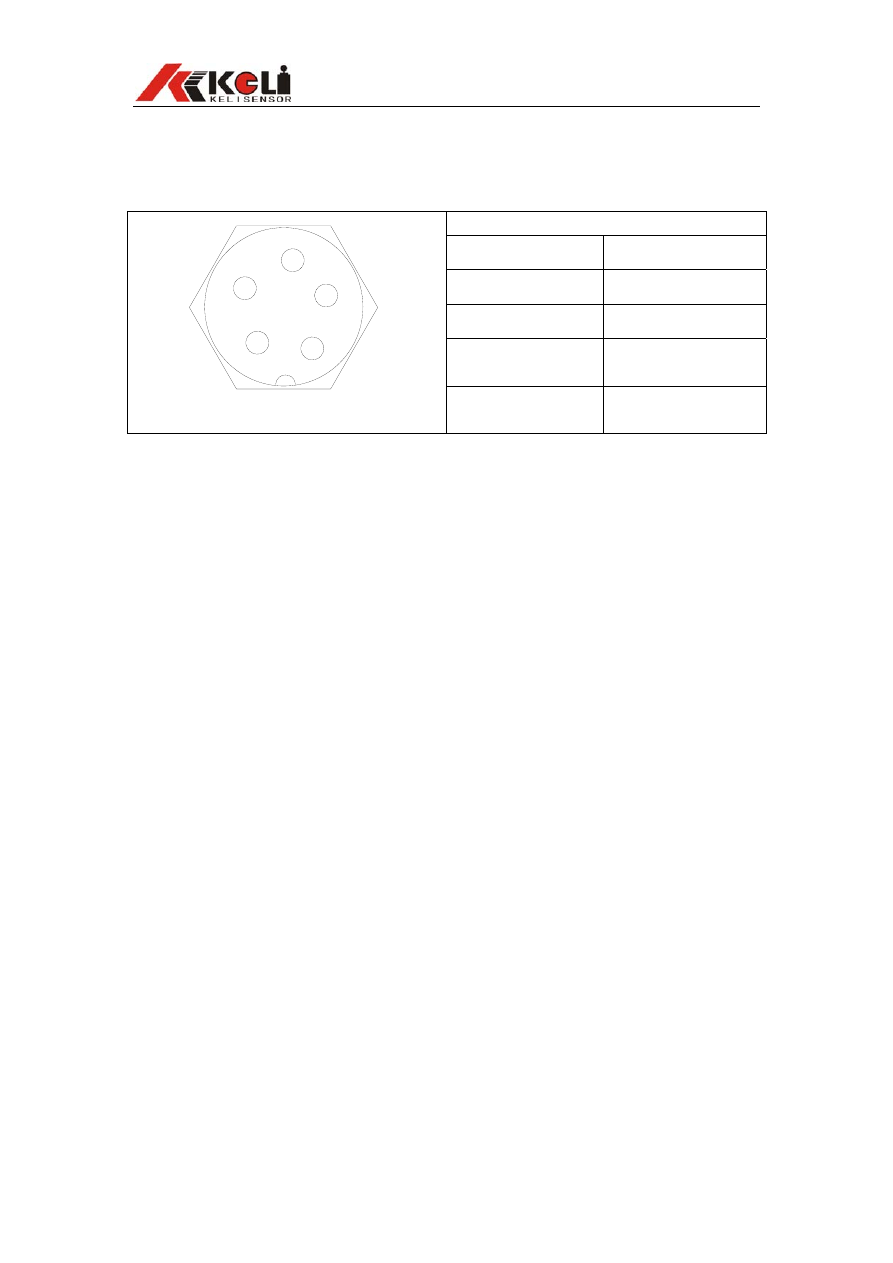
2.1.3 Serial Port Communication Wire Connection
Serial Port Chart
Port Assignment
①
RXD
②
TXD
③
GND
④
Current Loop Big
Screen Input
1
2
3
4
5
⑤
Current Loop Big
Screen Output
- 3 -

3.0 OPERATION
3.1 AUTO ZERO WHEN TURN ON AND OFF
The indicator power can be controlled by the on-off key on the front faceplate. The
indicator will perform self-check after turned on. If the scale was found departure from
the calibrate zero however still within the range of turn on auto zero then the indicator will
display “0” and the indicator light for “zero digit” will be on. If the scale was found
departure from the calibrate zero and out of the range of turn on auto zero then the
indicator will display the current read
If the range setting of the turn on zero is “- -“ which means zero of last turn off, then zero
operation will not be carried on and the zero of last turn off will be automatically readin
and the current weight will be displayed.
3.2 MANNUALLY ZERO
Indicator will back to zero when pressing “ZERO” key if the gross weight is within the
range of manually zero and stable. Manually zero is not valid under the “NET” displaying
mode;
3.3 TARE
TARE Operation can be carried out if both gross weight and net weight are above zero
and stable. The indicator will display “0” after pressing the “TARE” key. The tared weight
is current gross weight. And the indicator will enter “NET” displaying mode and the “NET”
indicator lights will be on;
The indicator will exit “NET” displaying mode after pressing “TARE” when the gross
weight is “0” and under “NET” displaying mode
3.4 OPERATION FOR TOTAL, TOTAL DISPLAY AND TOTAL CLEAR
1. In case, the net weight is bigger than the minimum measurable value (5 division) and
stable, when pressing “TOTAL”, the current net weight will be added and the “TOTAL”
indicator light will be on and total value will be displayed, which will be changed to adding
times【n ***】after 3 seconds and exit the total displaying status after another 3
seconds. Next operation will be only valid when the net weight is smaller than the
minimum measurable value.
2. If keep pressing “TOTAL” until buzzer alarms under the weighing status, “FUNCTION”
and “TOTAL” lights will be on and you can check the total value by pressing “↙” to see
the adding times and again “↙” to exit.
3. If you press “→” after keep pressing “TOTAL” and enter the total displaying status
there will be an notice 【CLRAr-】which means to clear the total value or not. Press “↙”
to clear and “FUNCTION” to exit and keep the value.
Operation as follows:
- 4 -
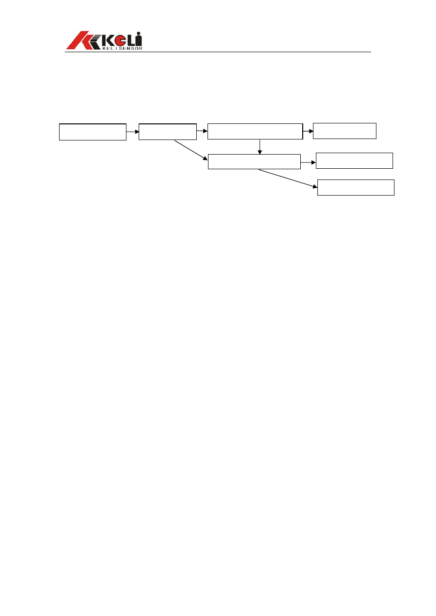
Press “↙” to exit
Press “↙” to see the
adding times
Display Total Value
3.5 OTHER PARAMETER SETTING AND FUNCTION
Parameter setting mode can be entered if keep pressing “FUNCTION” under normal
weighing status until buzzer alarms. Detailed operations are as follows:
Keep Pressing “TOTAL”
Press “↙” to confirm clear
Press “→” to clear total value
Press “FUNCTION’ to cancel
- 5 -
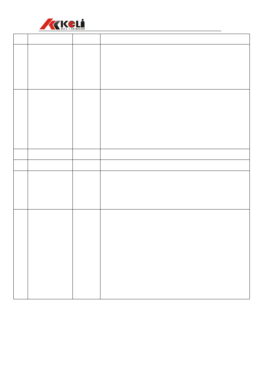
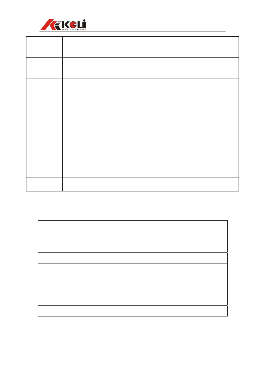
Steps Operations Display
Note
1
Keep Prssing
“FUNCTION” to Enter
“↑”to Switch
“↙”to Confirm
【
Fn **】
“Function” Setting:
【
Lb】:One Key Switch (kg/lb),(Not available under net weighing
status).
【
ANL】:Animal Scale, One key total and lock display.
【
--】:No Function
2
“↑”to Switch
“ ”to Confirm
↙
【
PS **】
Power Save Setting:
【
oFF】:Power save mode off
【
oN】:Open power save mode. The power save mode will be
entered 5 minutes after weight stable. The indicator will only display
date circultly in last digit
【
onP】:Enhanced power save mode which will automatically turn
off the indicator after 5 minutes power save mode.
3
“↑”to Switch
“ ”to Confirm
↙
【
br****】 Baud Rate Setting:600~9600bps Optional
4
“↑” to Switch
“ ” to Confirm
↙
【
Co *】 Communicate Mode Setting:1~6 Optional, Detailed format followed
5 High
Setting
【
H*****】
High Setting:
Press “→” the flash digit will move towards right
Press “↑” to increase the number of flash digit
Press “ ”to confirm and enter next step such as 2000
↙
6 Low
Setting
【
L*****】
Low Setting:
Press “→” the flash digit will move towards right
Press “↑” to increase the number of flash digit
Press “ ”to confirm and enter next step such as 1000
↙
If weight is higher than High setting the “HI” light on left side of the
indicator will be on
If weight is lower than Low setting the “LO” light on left side of the
indicator will be on
If the weight is between High and Low setting then the “OK” light will be on
COMMUNICATION MODE FORMAT:
- 6 -
Serial
Number
of each
frame
Note
1 8
Reversely send the Net Weight date. For example if the net weight is 23.45kg, ASCII
code 54.3200 will be sent. And if the net weight is –23.45kg, ASCII code 54.320- will
be sent.
2
8
Reversely send Gross Weight date. The format is same as serial 1
3 14
Positively send the Net Weight date with unit. For example if the netweightis 23.45kg,
ASCII code =0023.45(kg)will be sent.
End with Hex number OD,OA
4
14
Positively send the Net Weight date with unit. The format is same as serial 3
5
No
confirm
Order Response Mode:Order mode 02 “Order” 03(Hex)
There are 5 pieces order,ASCII code 'A'~'E'. Take gross weight 23.45kg,
netweight13.45kg and tare 10.00kg for example
'A':Read gross weight, indicator back:GW:0023.45(kg)
'B':Read net weight, indicator back:NW:0013.45(kg)
'C':Read tare, indicator back:TW:0010.00(kg)
'D':Manually zero, indicator back:'D'
'E':Tare operation, indicator back:'E'
All order back add 02 at the beginning and 03 at the end(Hex)
6
Net and total weight can be automatically output in Total operation and the date can
be printed if connected with serial printer
4.0 ERROR NOTICE
Display Note
Err 01
Exceed the Zero Range
Err 02
Not Meet the Requirement of Total
Err 03
Weight Overloaded
Err 04
Weight not stable during Calibration
Err 05
Load Calibration Error. Too low load or Calibration code too small or AD
reverse
Err 09
Data read verify Error, Data Memory Damaged
Err 10
Boot verify Error, SCM damaged
- 7 -

Keli Eelectric Manufacturing (Ningbo) Co., Ltd.
ADD: No. 199 Changxing Road, Jiangbei C District, Ningbo China
TEL.:0574-87562222
FAX:0574-87562211
ZIP CODE:315033
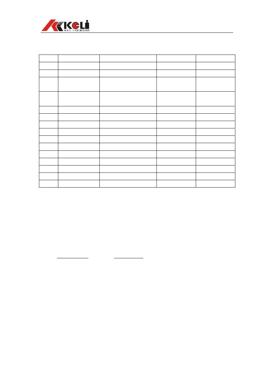
XK3118T1 Packing List
Serial Name
Model
no.
Quantity Remarks
1 Indicator
XK3118T1
1pc
2 Adapter
10.5V1A
1pc
3 Communication
Plug
9 Core D Type(Pin)
1pc
4
9 Core D Type
Jacket
1pc
5 Manual
1pc
6 Certificate
1pc
7
8
9
10
11
12
13
14
15
Pack: Check:
Document Outline
Wyszukiwarka
Podobne podstrony:
cas test platform user manual
CARPROG Opel ECU programmer user manual
elm327 interface viecar obd2 bluetooth scanner user manual
autel power scan ps100 user manual
Chartplanner user manual
INPA User manual
all100 user manual
CARPROG user manual
FX2N 485 BD User's Manual JY992 Nieznany
mb sbc tool user manual
07 Altistart48 user manual
iphone user manual pdf
PRDM 0010 Upgrade user manual UPG 0001
TK105 GPS Tracker User Manual
ATDSK1118 User Manual
FX2N 232 IF User's Manual JY992D66701
Protek 3502C USER MANUAL
Administrator User Manual
NMS KD 0017 en V01 03 N3000 IMC and ISC User Manual
więcej podobnych podstron