Data Sheet
27621.6B*
Always order by complete part number, e.g., A3141ELT .
ABSOLUTE MAXIMUM RATINGS
at T
A
= +25
°
C
Supply Voltage, V
CC
............................ 28 V
Reverse Battery Voltage, V
RCC
........... -35 V
Magnetic Flux Density, B .......... Unlimited
Output OFF Voltage, V
OUT
.................. 28 V
Reverse Output Voltage, V
OUT
........... -0.5 V
Continuous Output Current, I
OUT
...... 25 mA
Operating Temperature Range, T
A
Suffix ‘E–’ .................. -40
°
C to +85
°
C
Suffix ‘L–’ ................ -40
°
C to +150
°
C
Storage Temperature Range,
T
S
.............................. -65
°
C to +170
°
C
These Hall-effect switches are monolithic integrated circuits with
tighter magnetic specifications, designed to operate continuously over
extended temperatures to +150
°
C, and are more stable with both
temperature and supply voltage changes. The unipolar switching
characteristic makes these devices ideal for use with a simple bar or rod
magnet. The four basic devices (3141, 3142, 3143, and 3144) are
identical except for magnetic switch points.
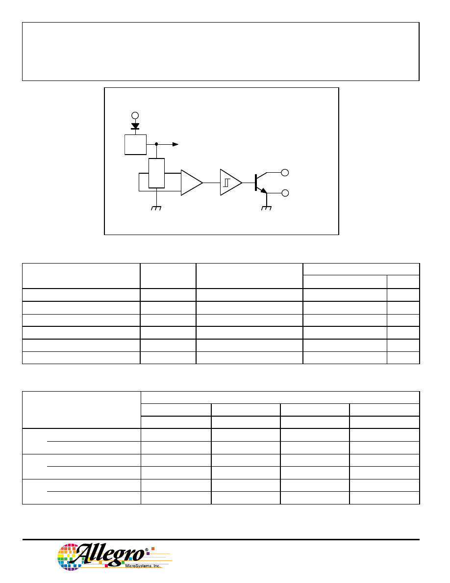
Each device includes a voltage regulator for operation with supply
voltages of 4.5 to 24 volts, reverse battery protection diode, quadratic
Hall-voltage generator, temperature compensation circuitry, small-
signal amplifier, Schmitt trigger, and an open-collector output to sink
up to 25 mA. With suitable output pull up, they can be used with
bipolar or CMOS logic circuits. The A3141– and A3142– are im-
proved replacements for the UGN/UGS3140–; the A3144– is the
improved replacement for the UGN/UGS3120–.
The first character of the part number suffix determines the device
operating temperature range. Suffix ‘E–’ is for the automotive and
industrial temperature range of -40
°
C to +85
°
C. Suffix ‘L–’ is for the
automotive and military temperature range of -40
°
C to +150
°
C. Three
package styles provide a magnetically optimized package for most
applications. Suffix ‘–LT’ is a miniature SOT89/TO-243AA transistor
package for surface-mount applications; suffix ‘–UA’ is a three-lead
ultra-mini-SIP.
FEATURES and BENEFITS
■ Superior Temp. Stability for Automotive or Industrial Applications
■ 4.5 V to 24 V Operation … Needs Only An Unregulated Supply
■ Open-Collector 25 mA Output … Compatible with Digital Logic
■ Reverse Battery Protection
■ Activate with Small, Commercially Available Permanent Magnets
■ Solid-State Reliability
■ Small Size
■ Resistant to Physical Stress
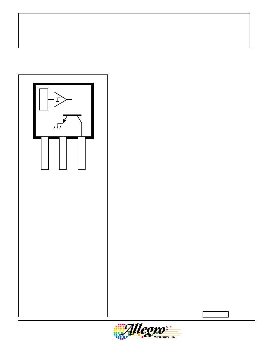
Pinning is shown viewed from branded side.
SENSITIVE HALL-EFFECT SWITCHES
FOR HIGH-TEMPERATURE OPERATION
3141
THRU
3144
Dwg. PH-003A
1
SUPPLY
V
CC
GROUND
3
2
OUTPUT
X
3141
THRU
3144
SENSITIVE
HALL-EFFECT SWITCHES
FOR HIGH-TEMP. OPERATION
115 Northeast Cutoff, Box 15036
Worcester, Massachusetts 01615-0036 (508) 853-5000
FUNCTIONAL BLOCK DIAGRAM
V
CC
X
REG.
Dwg. FH-005-2
GROUND
OUTPUT
3
2
1
MAGNETIC CHARACTERISTICS in gauss over operating supply voltage range.
NOTES: Typical values are at T
A
= +25
°
C and V
CC
= 8 V.
B
OP
= operate point (output turns ON); B
RP
= release point (output turns OFF); B
hys
= hysteresis (B
OP
- B
RP
).
1 gauss (G) is exactly equal to 0.1 millitesla (mT).
*Complete part number includes a suffix to identify operating temperature range (E- or L-) and package type ( -LT or -UA).
ELECTRICAL CHARACTERISTICS at V
CC
= 8 V over operating temperature range.
Limits
Characteristic
Symbol
Test Conditions
Min.
Typ.
Max.
Units
Supply Voltage
V
CC
Operating
4.5
—
24
V
Output Saturation Voltage
V
OUT(SAT)
I
OUT
= 20 mA, B > B
OP
—
175
400
mV
Output Leakage Current
I
OFF
V
OUT
= 24 V, B < B
RP
—
<1.010
µ
A
Supply Current
I
CC
B < B
RP
(Output OFF)
—
4.4
9.0mA
Output Rise Time
t
r
R
L
= 820
Ω
, C
L
= 20 pF
—
0.04
2.0
µ
s
Output Fall Time
t
f
R
L
= 820
Ω
, C
L
= 20 pF
—
0.18
2.0
µ
s
Part Numbers*
A3141–
A3142–
A3143–
A3144–
Characteristic
Min.
Typ.
Max.
Min.
Typ.
Max.
Min.
Typ.
Max.
Min.
Typ.
Max.
B
OP
at T
A
= 25
°
C
5010
0160 130180230 220280340
70 —
350
over operating temp. range
3010
0175
115
180245
20
5
280355
35
—
450
B
RP
at T
A
= 25
°
C
1045
130
75
125
175
165
225
285
50—
330
over operating temp. range
1045
145
60
125
190 150
225
30
0 25
—
430
B
hys
at T
A
= 25
°
C
2055
80
3055
80 3055
80 2055
—
over operating temp. range
2055
80
3055
80 3055
80 2055
—
Copyright © 1993, 2002 Allegro MicroSystems, Inc.
3141
THRU
3144
SENSITIVE
HALL-EFFECT SWITCHES
FOR HIGH-TEMP. OPERATION
www.allegromicro.com
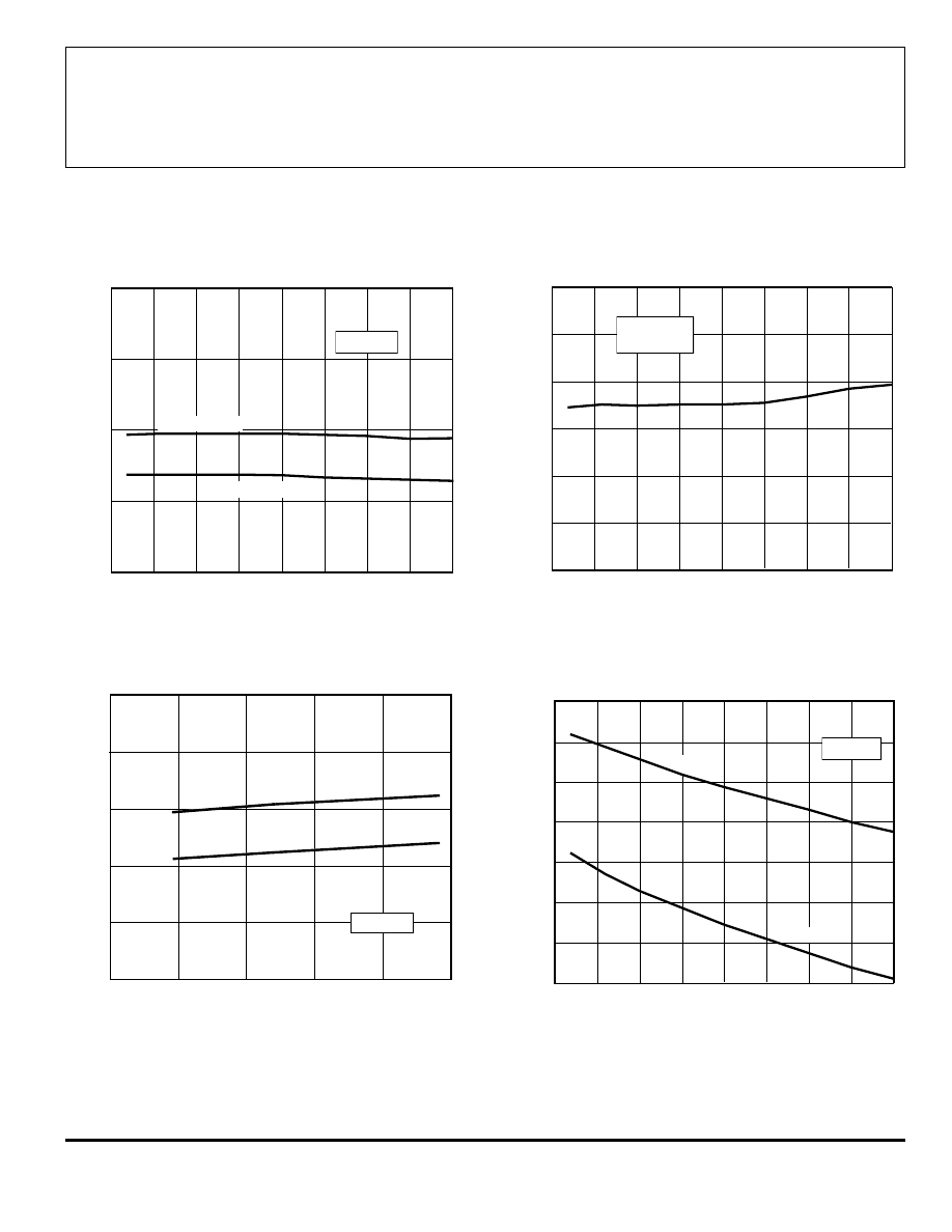
SUPPLY CURRENT
SUPPLY CURRENT
10
15
20
25
SUPPLY VOLTAGE IN VOLTS
0
Dwg. GH-041-1
5
SUPPLY CURRENT IN mA
0
2.0
4.0
6.0
8.0
10
B
≥
B
OP
B
≤
B
RP
T = +25
°
C
A
0
25
50
75
100
AMBIENT TEMPERATURE IN
°°°°
C
-50
Dwg. GH-039-1
125
-25
V = 8 V
CC
SUPPLY CURRENT IN mA
7.0
6.0
5.0
4.0
150
B
≤
B
RP
B
≥
B
OP
TYPICAL OPERATING CHARACTERISTICS
A3142– SWITCH POINTS
OUTPUT SATURATION VOLTAGE
0
25
50
75
100
300
0
AMBIENT TEMPERATURE IN
°°°°
C
200
100
-50
Dwg. GH-040-1
SATURATION VOLTAGE IN mV
150
-25
125
I = 20 mA
V = 4.5–24 V
OUT
CC
0
50
100
AMBIENT TEMPERATURE IN
°°°°
C
-50
Dwg. GH-044
SWITCH POINT IN GAUSS
300
400
200
100
OPERATE POINT
RELEASE POINT
V = 8 V
CC
150
0
-25
25
75
125
* Complete part number includes a suffix denoting operating temperature range (E- or L-) and package type ( -LT, -U, or -UA).
3141
THRU
3144
SENSITIVE
HALL-EFFECT SWITCHES
FOR HIGH-TEMP. OPERATION
115 Northeast Cutoff, Box 15036
Worcester, Massachusetts 01615-0036 (508) 853-5000
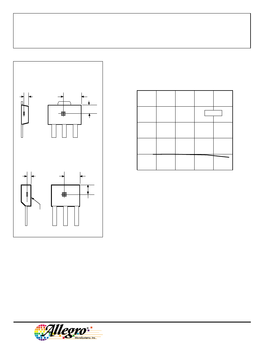
TYPICAL OPERATING CHARACTERISTICS (cont.)
CHANGE IN OPERATE POINT
10
15
20
25
SUPPLY VOLTAGE IN VOLTS
0
Dwg. GH-042-1
5
CHANGE IN OPERATE POINT IN GAUSS
-5.0
0
5.0
10
15
20
T = +25
°
C
A
OPERATION
The output of these devices (pin 3) switches low when the magnetic field
at the Hall sensor exceeds the operate point threshold (B
OP
). At this point, the
output voltage is V
OUT(SAT)
. When the magnetic field is reduced to below the
release point threshold (B
RP
), the device output goes high. The difference in
the magnetic operate and release points is called the hysteresis (B
hys
) of the
device. This built-in hysteresis allows clean switching of the output even in
the presence of external mechanical vibration and electrical noise.
Extensive applications information for Hall-effect sensors is available in:
• Hall-Effect IC Applications Guide, Application Note 27701;
• Hall-Effect Devices: Soldering, Gluing, Potting, Encapsulating, and Lead
Forming, Application Note 27703.1;
• Soldering of Through-Hole Hall-Sensor Dervices, Application Note 27703;
and
• Soldering of Surface-Mount Hall-Sensor Devices, Application Note 27703.2.
All are provided in Allegro Electronic Data Book, AMS-702. or at
www.allegromicro.com
SENSOR LOCATIONS
(
±
0.005” [0.13 mm] die placement)
1
3
2
Dwg. MH-011-10A
0.0195"
0.50 mm
NOM
BRANDED
SURFACE
ACTIVE AREA DEPTH
0.082"
2.07 mm
0.055"
1.39 mm
A
Suffix “UA”
Suffix “LT”
0.043"
1.09 mm
1
3
2
Dwg. MH-008-2D
0.0305"
0.775 mm
NOM
ACTIVE AREA DEPTH
0.089"
2.26 mm
A
Allegro
3141
THRU
3144
SENSITIVE
HALL-EFFECT SWITCHES
FOR HIGH-TEMP. OPERATION
www.allegromicro.com
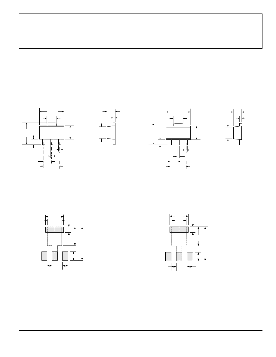
Dwg. MA-009-3A in
1
2
3
0.072
0.064
0.167
0.155
0.059
BSC
0.0189
0.0142
0.047
0.035
0.102
0.090
0.063
0.055
0.0173
0.0138
0.090
0.084
0.0221
0.0173
0.118
BSC
0.181
0.173
Dwg. MA-009-3A mm
1
2
3
4.60
4.40
1.83
1.62
4.25
3.94
1.50
BSC
0.48
0.36
1.20
0.89
2.60
2.29
1.60
1.40
0.44
0.35
2.29
2.13
0.56
0.44
3.00
BSC
PACKAGE DESIGNATOR ‘LT’
(SOT89/TO-243AA)
Dimensions in Inches
(for reference only)
Dimensions in Millimeters
(controlling dimensions)
NOTES: 1.
Exact body and lead configuration at vendor’s option within limits shown.
2.
Supplied in bulk pack (500 pieces per bag) or add "TR" to part number for tape and reel.
3.
Only low-temperature (
≤
240
°
C) reflow-soldering techniques are recommended for SOT89 devices.
1
B
0.098
0.031
0.102
0.047
0.181
0.079
Dwg. MA-012-3 in
Pads 1, 2, 3, and A — Standard SOT89 Layout
Pads 1, 2, 3, and B — Low-Stress Version
Pads 1, 2, and 3 only — Lowest Stress, But Not Self Aligning
2
0.028
TYP
0.031
TYP
A
3
1
3
B
2.5
0.8
2.6
1.2
4.6
2.0
Dwg. MA-012-3 mm
Pads 1, 2, 3, and A — Standard SOT89 Layout
Pads 1, 2, 3, and B — Low-Stress Version
Pads 1, 2, and 3 only — Lowest Stress, But Not Self Aligning
2
0.7
TYP
0.8
TYP
A
3141
THRU
3144
SENSITIVE
HALL-EFFECT SWITCHES
FOR HIGH-TEMP. OPERATION
115 Northeast Cutoff, Box 15036
Worcester, Massachusetts 01615-0036 (508) 853-5000
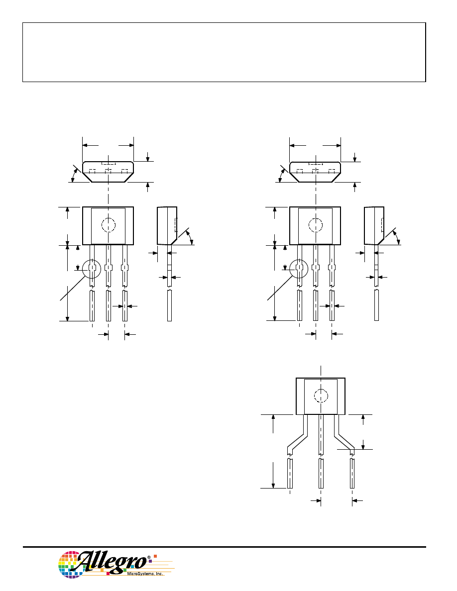
Dimensions in Inches
(controlling dimensions)
Dimensions in Millimeters
(for reference only)
PACKAGE DESIGNATOR ‘UA’
NOTES: 1.
Tolerances on package height and width represent
allowable mold offsets. Dimensions given are
measured at the widest point (parting line).
2.
Exact body and lead configuration at vendor’s option
within limits shown.
3.
Height does not include mold gate flash.
4.
Recommended minimum PWB hole diameter to clear
transition area is 0.035" (0.89 mm).
5.
Where no tolerance is specified, dimension is nominal.
6.
Supplied in bulk pack (500 pieces per bag).
Dwg. MH-014E in
0.164
0.159
0.062
0.058
0.0173
0.0138
0.050
BSC
45
°
0.640
0.600
0.0189
0.0142
0.085
MAX
45
°
0.031
1
2
3
0.122
0.117
SEE NOTE
Dwg. MH-014E mm
4.17
4.04
1.57
1.47
0.44
0.35
1.27
BSC
45
°
16.26
15.24
0.48
0.36
2.16
MAX
45
°
0.79
1
2
3
3.10
2.97
SEE NOTE
Radial Lead Form (order A314xxUA-LC)
NOTE:
Lead-form dimensions are the nominals produced on the
forming equipment. No dimensional tolerance is implied or
guaranteed for bulk packaging (500 pieces per bag).
0.620"
0.500"
(15.7 mm
12.7 mm)
0.100"
(2.5 mm)
Dwg. MH-026
0.108"
(2.74 mm)
1
2
3
3141
THRU
3144
SENSITIVE
HALL-EFFECT SWITCHES
FOR HIGH-TEMP. OPERATION
www.allegromicro.com
HALL-EFFECT SENSORS
UNIPOLAR HALL-EFFECT DIGITAL SWITCHES
Partial
Operate
Release
Hysteresis
Replaces
Part
Point (G)
Point (G)
(G)
Oper.
and
Number
Over Oper. Voltage & Temp. Range
Temp.
Packages
Comments
A3121x
220 to 500
80 to 410
60 to 150
E, L
LT, UA
3019, 3113, 3119
A3122x
260 to 430
120 to 360
70 to 140
E, L
LT, UA
A3123x
230 to 470
160 to 330
70 to 140
E, L
LT, UA
A3141x
30 to 175
10 to 145
20 to 80
E, L
LT, UA
3040, 3140
A3142x
115 to 245
60 to 190
30 to 80
E, L
LT, UA
A3143x
205 to 355
150 to 300
30 to 80
E, L
LT, UA
A3144x
35 to 450
25 to 430
>20
E, L
LT, UA
3020, 3120
A3161E
<160 (Typ 130)
>30 (Typ 110)
5 to 80
E
LT, UA
2-wire operation
A3163E
<160 (Typ 98)
>30 (Typ 79)
5 to 40
E
LT, UA
2-wire
A3240x
<50 (Typ 35)
>5 (Typ 25)
Typ 10
E, L
LH, LT, UA
chopper stabilized
A3250x
<50 to >350
_
5 to 35
J, L
UA
programmable, chopper stabilized
A3251x
<50 to >350
_
5 to 35
J, L
UA
programmable, chopper stabilized
A3361E
<125
>405 to 30E
LH, LT, UA
2-wire, chopper stabilized,
output normally high
A3362E
<125
>405 to 30E
LH, LT, UA
2-wire, chopper stabilized,
output normally low
MICROPOWER OMNIPOLAR HALL-EFFECT DIGITAL SWITCHES
Partial
Operate
Release
Hysteresis
Average
Part
Points (G)
Points (G)
(G)
Oper.
Supply
Number
Over Oper. Voltage & Temp. Range
Temp.
Packages
Current (
µ
A)
A3209E
>-60, <60
<-5, >5
Typ 7.7
E
LH, UA
<425 (Typ 145)
A3210E
>-60, <60
<-5, >5
Typ 7.7
E
LH, UA
<60 (Typ 8.8)
A3212E
>-55, <55
<-10, >10
Typ. 8
E
LH, UA
<10 (Typ 4.2)
BIPOLAR HALL-EFFECT DIGITAL SWITCHES
Partial
Operate
Release
Hysteresis
Replaces
Part
Point (G)
Point (G)
(G)
Oper.
and
Number
Over Oper. Voltage & Temp. Range
Temp.
Packages
Comments
UGx3132
<95 (Typ 32)
>-95 (Typ -20) >30 (Typ 52)
K, L, S
LT, UA
3030, 3130, 3131
UGx3133
<75 (Typ 32)
>-75 (Typ -20) >30 (Typ 52)
K, L, S
LT, UA
UGx3134
-40 to 50
-50 to 40
5 to 55
E, L
LT, UA
A3260x
<30 (Typ 10)
>-30 (Typ -10)
Typ 20
E, L
LH, LT, UA
2 wire, chopper stabilized
Notes: 1) Typical data is at TA = +25
°
C and nominal operating voltage.
2) “x” = Operating Temperature Range [suffix letter or (prefix)]: S (UGN) = -20
°
C to +85
°
C, E = -40
°
C to +85
°
C,
J = -40
°
C to +115
°
C, K (UGS) = -40
°
C to +125
°
C, L (UGL) = -40
°
C to +150
°
C.

3141
THRU
3144
SENSITIVE
HALL-EFFECT SWITCHES
FOR HIGH-TEMP. OPERATION
115 Northeast Cutoff, Box 15036
Worcester, Massachusetts 01615-0036 (508) 853-5000
The products described herein are manufactured under one or more
of the following U.S. patents: 5,045,920; 5,264,783; 5,442,283;
5,389,889; 5,581,179; 5,517,112; 5,619,137; 5,621,319; 5,650,719;
5,686,894; 5,694,038; 5,729,130; 5,917,320; and other patents
pending.
Allegro MicroSystems, Inc. reserves the right to make, from time to
time, such departures from the detail specifications as may be required
to permit improvements in the performance, reliability, or
manufacturability of its products. Before placing an order, the user is
cautioned to verify that the information being relied upon is current.
Allegro products are not authorized for use as critical components
in life-support appliances, devices, or systems without express written
approval.
The information included herein is believed to be accurate and
reliable. However, Allegro MicroSystems, Inc. assumes no responsibil-
ity for its use; nor for any infringements of patents or other rights of
third parties that may result from its use.
Wyszukiwarka
Podobne podstrony:
3141
3141
3141
3141
3141
iPhone 5 Boardview 820 3141 B
więcej podobnych podstron