
Techinical Drawings for the
Mission Video Cabinet
Walt Akers - 1998
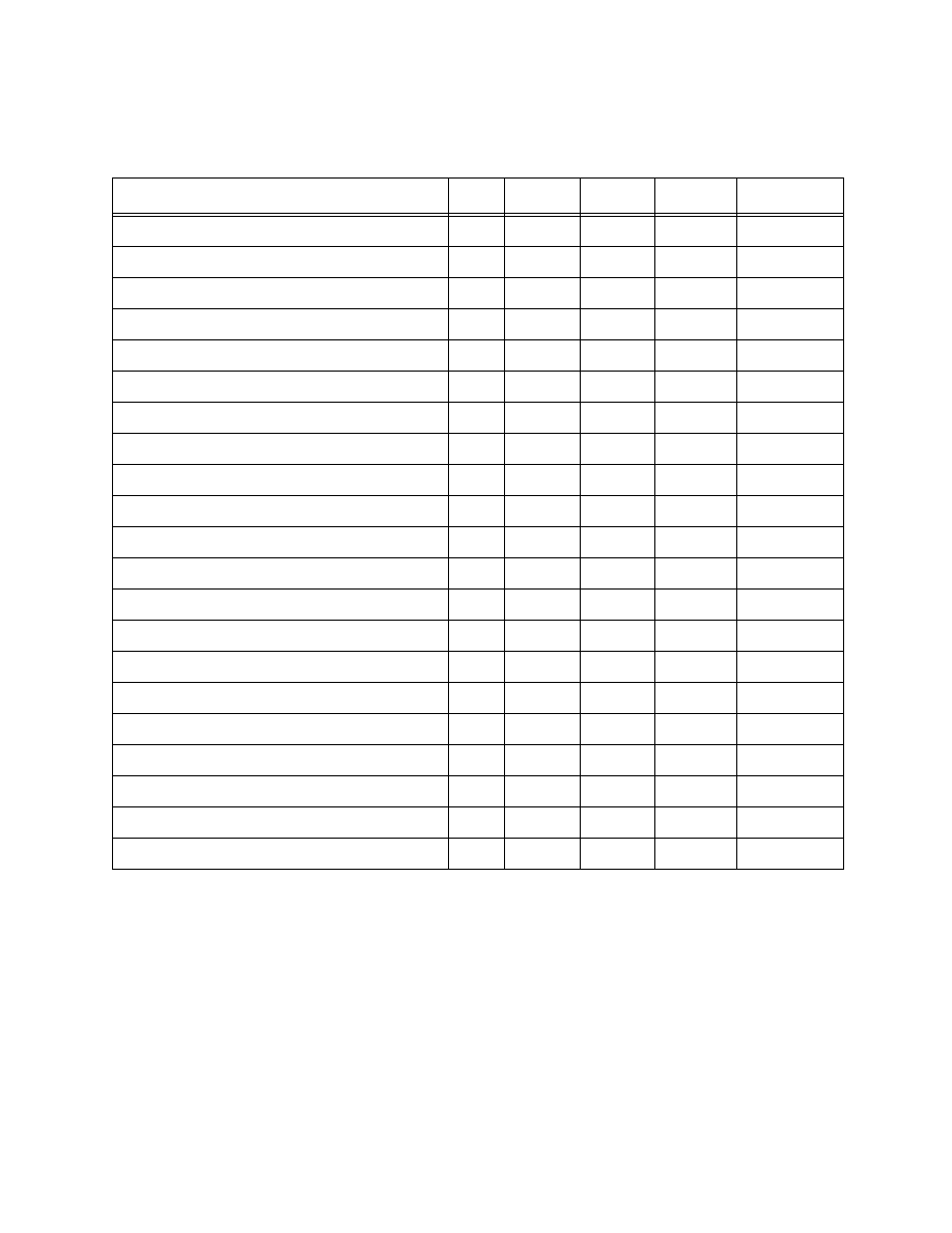
Table 1: Cabinet Components, Dimensions and Materials
Component / Location
Req
Length
Width
Thickness
Material
Cabinet Top Plank / Top
4
49
6.5
3/4
White Oak
Side Crown Molde / Crown
2
25 1/2
2 3/8
3/4
White Oak
Front Crown Molde / Crown
1
47 3/4
2 3/8
3/4
White Oak
Stretcher / Carcasse Top - Shelf Fronts
4
41
1.5
1
White Oak
Shelves / Carcasse
2
41.75
21.75
3/4
Oak Plywood
Side Rails / Carcasse
6
49.5
1.5
1
White Oak
Side Panels / Carcasse
8
49.5
5 1/8
3/4
White Oak
Side Base Mould / Base
2
23.75
6.5
3/4
White Oak
Front Base Mould / Base
1
44.5
6.5
3/4
White Oak
Door Rail / Door
4
33
3
3/4
White Oak
Door Center Rail / Door
2
25
3
3/4
White Oak
Door Top Stile / Door
2
16
3
3/4
White Oak
Door Bottom Stile / Door
2
16
5
3/4
White Oak
Door Panel / Door
4
24.75
6.75
1/2
White Oak
Door Spacer Bar / Left Door
1
33
1.0
3/4
White Oak
Door Spacer Backing / Left Door
1
33
2.25
1/2
White Oak
Drawer Front / Drawer
1
41
7
3/4
White Oak
Drawer Side / Drawer
2
22
6
1/2
Oak Plywood
Drawer Back / Drawer
1
39.5
5 3/8
1/2
Oak Plywood
Drawer Bottom / Drawer
1
39.5
21.75
1/4
Oak Plywood
Cabinet Back / Carcasse
1
41 3/4
42 3/8
1/4
Oak Plywood
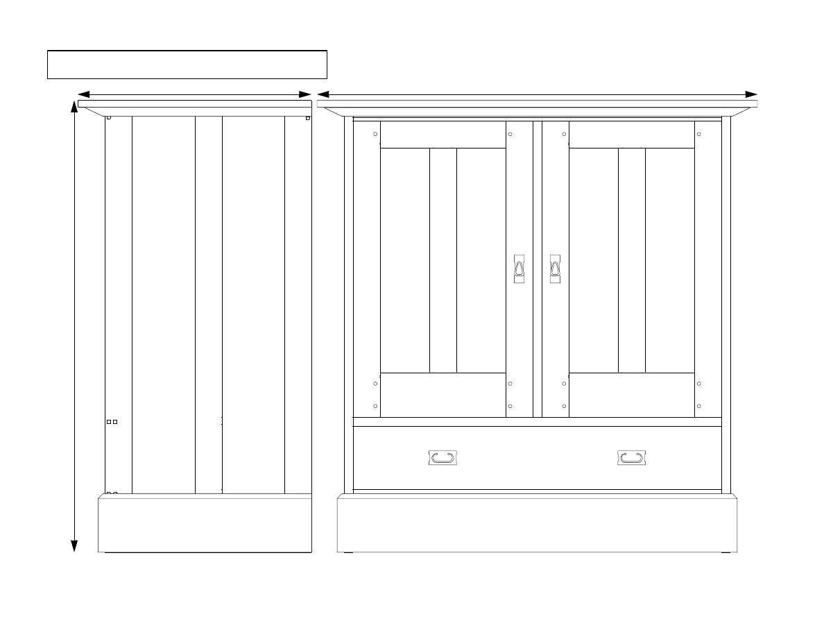
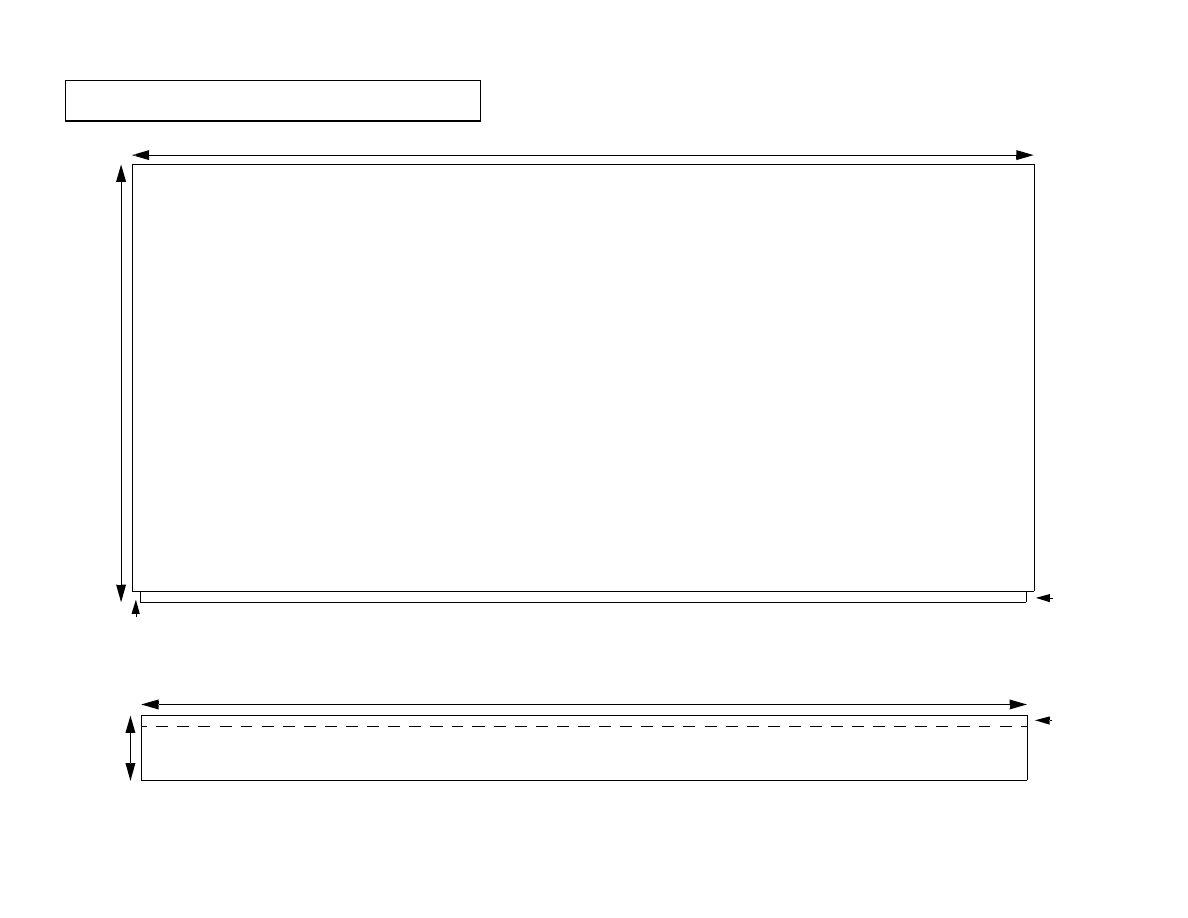
Assembled Entertainment Cabinet
26.0 in
50.
25 in
49.0 in
49.0 in
2
6
.0
i
n
6.
5 i
n
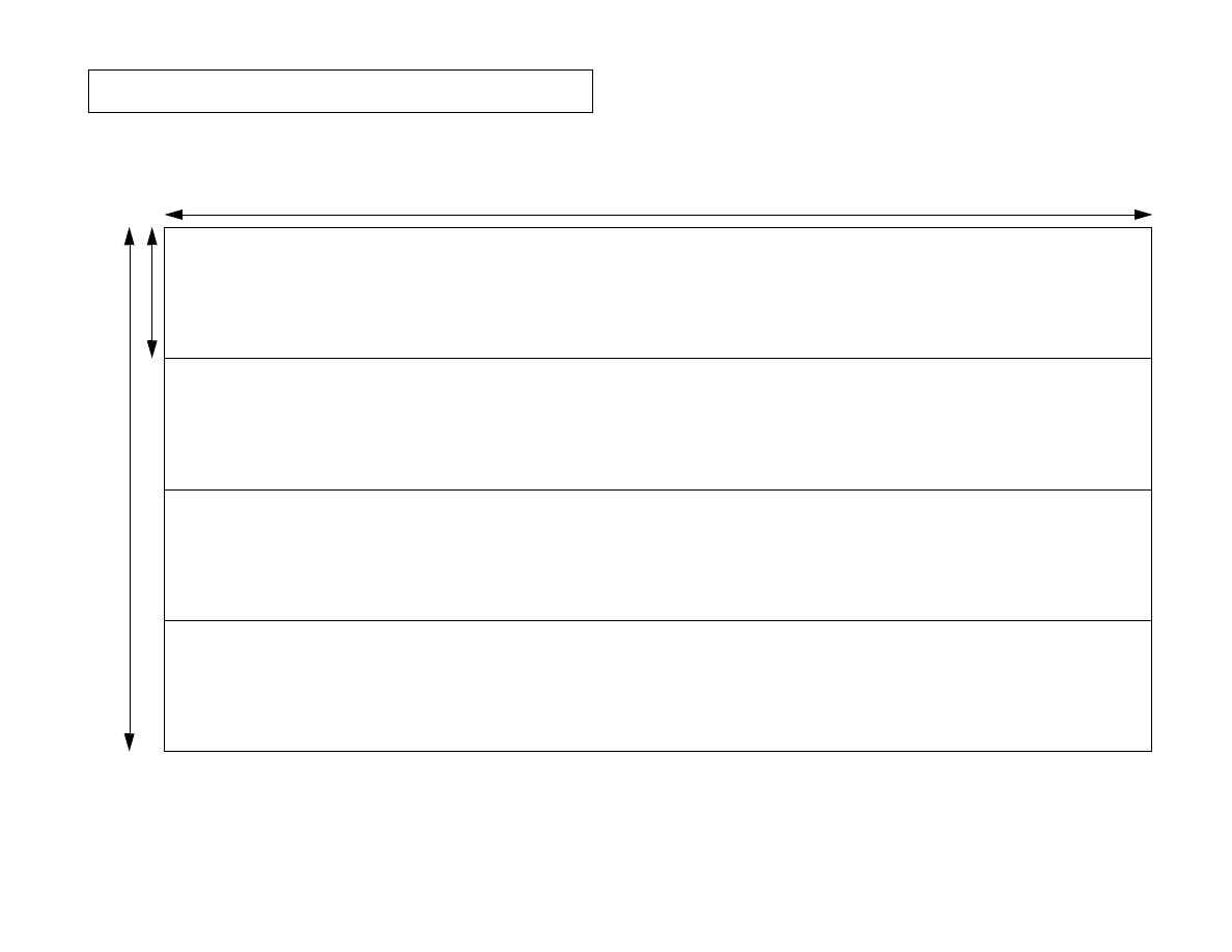
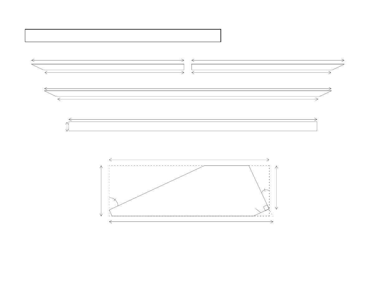
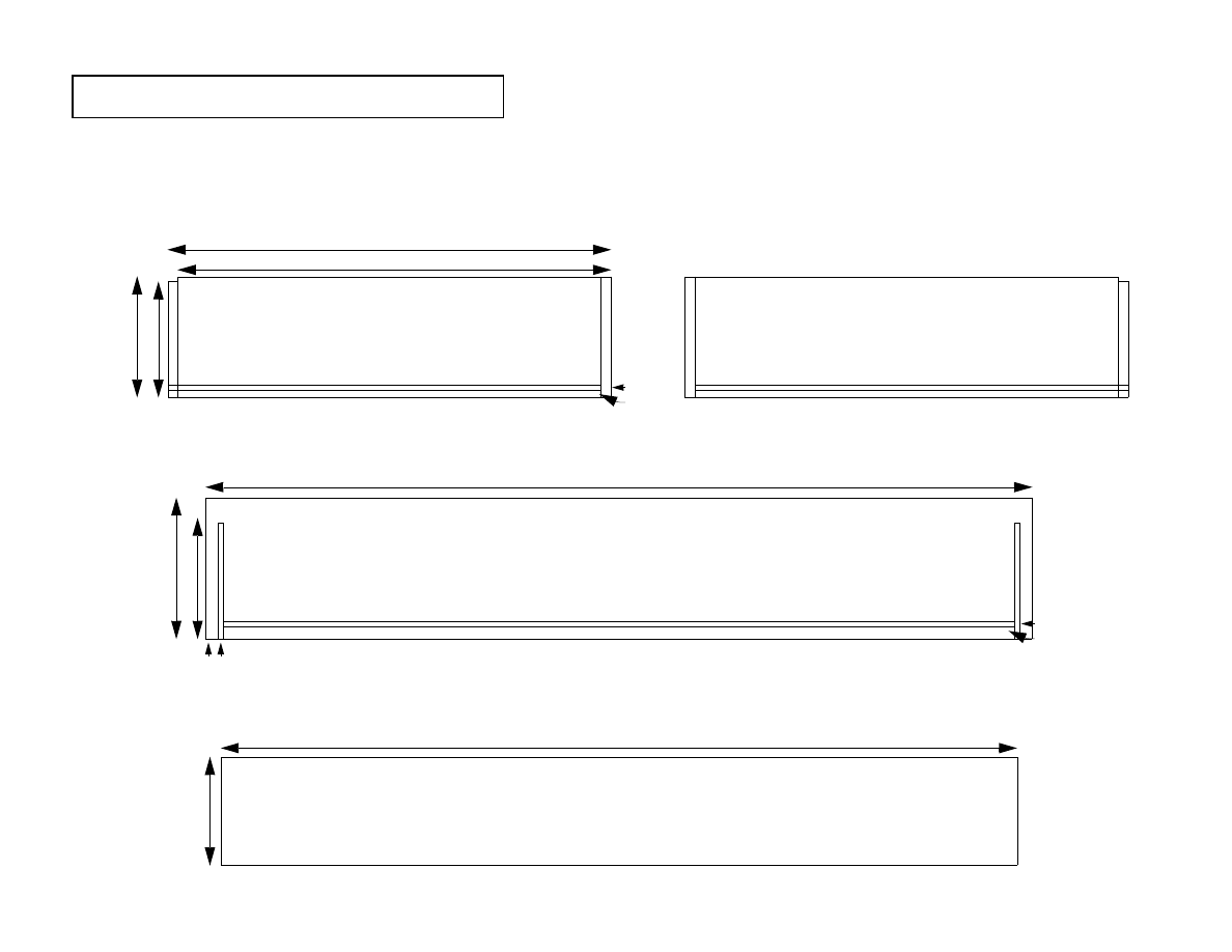
Components of the Cabinet Top - Option 2
Construction of the Cabinet Top
Millwork:
1
Cut, plane and joint four boards to the following dimensions.
A
One (1) at 49” x 6 1/2” x 3/4”.
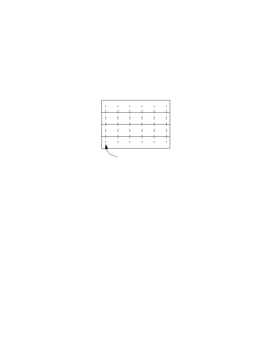
Assembly:
1
Lay boards side by side, and rotate them to alternate their growth rings.
2
Align the left edge of all four boards and draw a registration mark at 2 inches from this edge.
3
Repeat 5 additional registration marks every 9 inches. These marks indicate where the biscuit slots will
be cut.
4
Using the biscuit cutter, install number twenty biscuits slots at each registration point.
5
Install biscuits and glue and clamp work piece together.
Registration Mark
2
”
9.
0”
9.
0”
9.
0”
9.
0”
9.
0”
43.0 in
47.354 in
23.0 in
25.177 in
23.0 in
25.177 in
0.25 in
0.
75
i
n
2.375 in
2.42427 in
25
°
65
°
0.
64
435 i
n
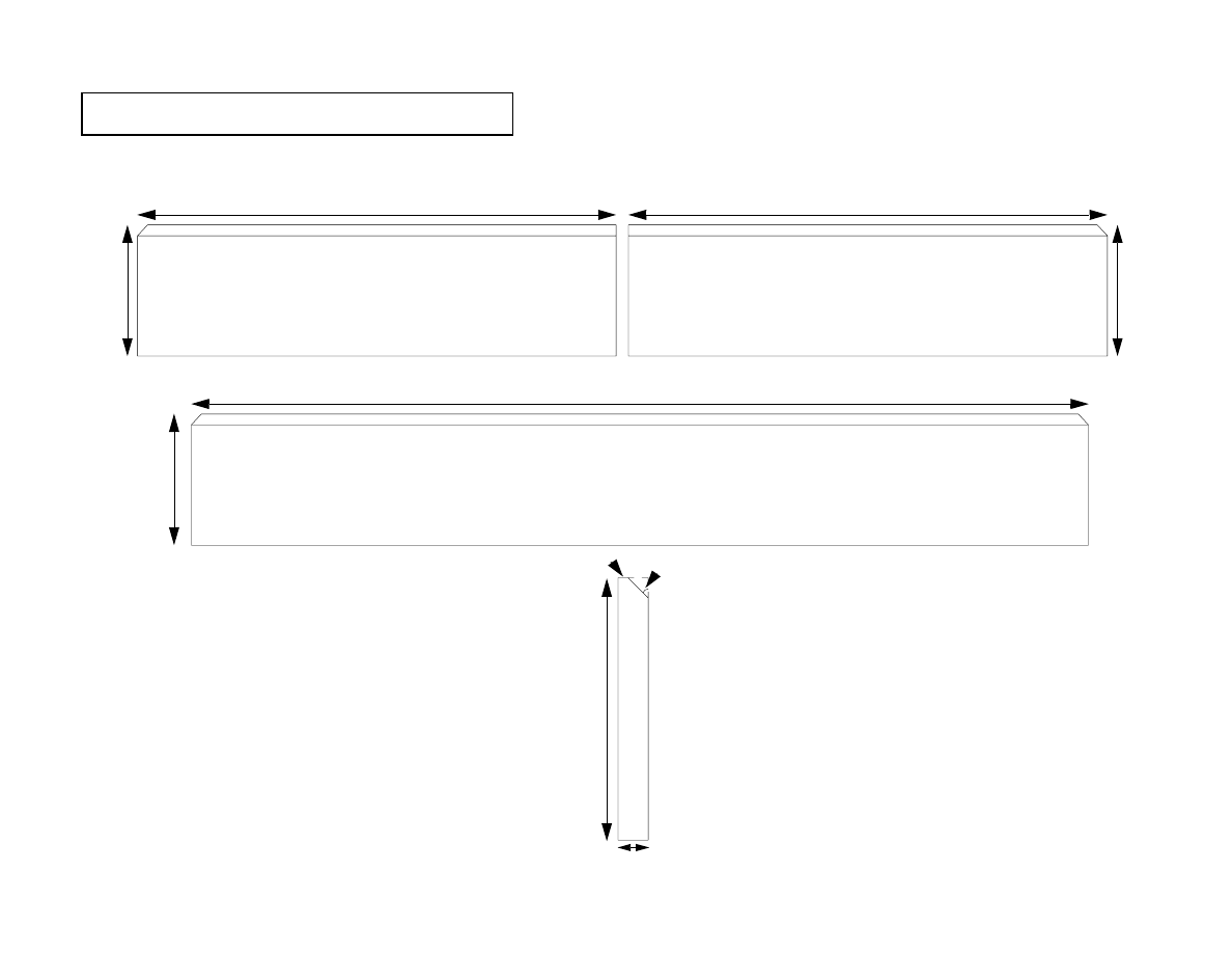
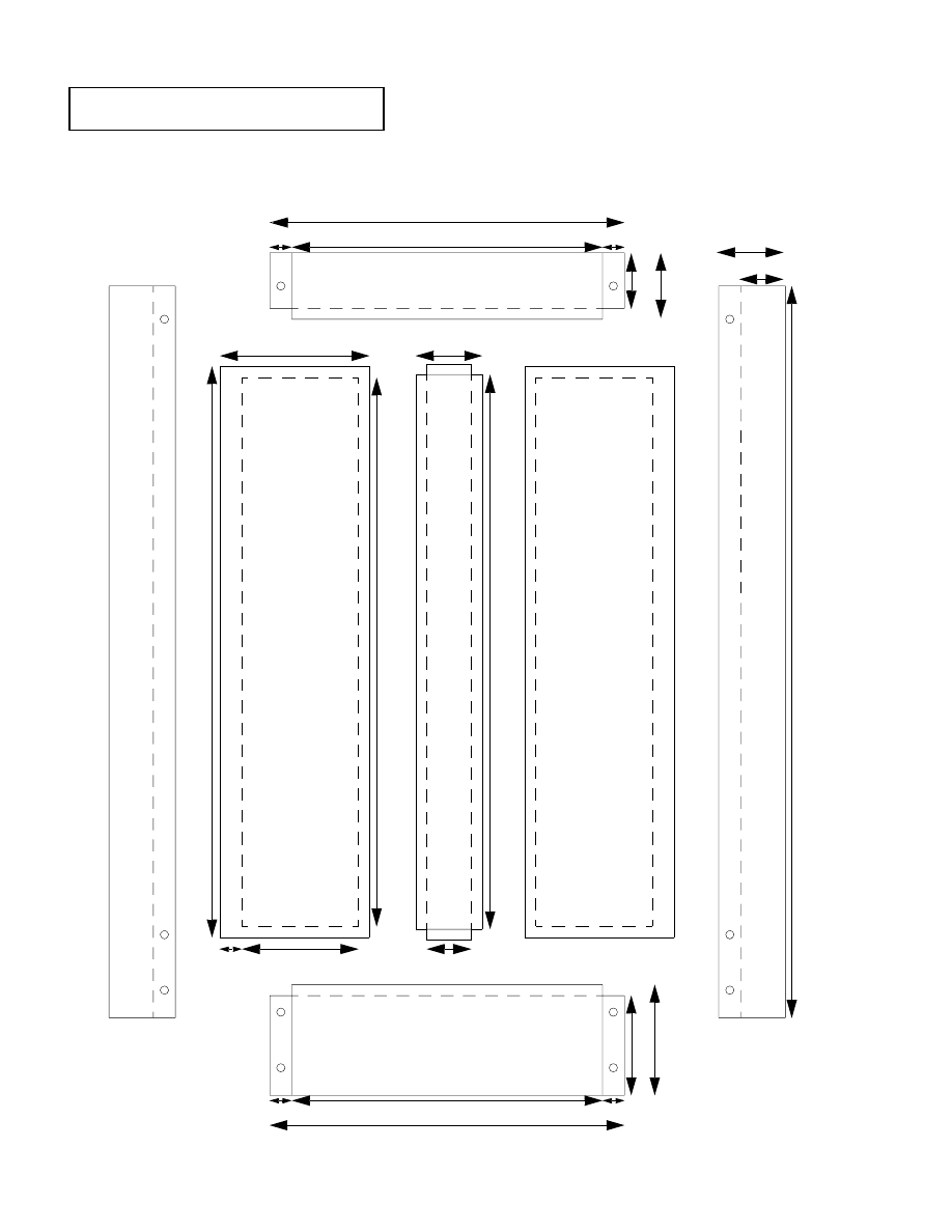
Crown Molding and Cabinet Top Stiles
41.0 in
1.
5 i
n

Construction of the Crown Molding
Millwork:
1
Cut, plane and joint three sections of white oak to the following dimensions.
A
Two (2) at 25 1/2” x 2 3/8” x 3/4”
B
One (1) at 48” x 2 3/8” x 3/4”
2
Set the tablesaw bevel to 25 degrees.
3
Position the fence 2 7/16” to the left of the blade.
4
Placing the 2 3/8” side of each board against the table, rip the 3/4” side to 25 degrees.
5
Position the fence 1/8” to the right of the blade.
6
Placing the uncut 3/4” side of each board against the table, bevel the 2 3/8” side. Use featherboards as
necessary to keep the board tight against the fence.
7
Return the blade to 0 degrees bevel.
8
Attach a sacrificial strip to the tablesaw fence and position the fence against the blade.
9
Cut the remaining edges of the workpiece.
10 Do not cut the 45 degree angles on these pieces until the carcase has been completed and measured.
Assembly:
No independent assembly is required of these components.
Construction of the Cabinet Top Stretchers
Millwork:
1
Cut, plane and joint two sections of white oak to the following dimensions.
A
Two (2) at 41” x 1 1/2” x 3/4”
Assembly:
No independent assembly is required of these components.
23.75 in
6.
5 i
n
6.
5 i
n
44.5 in
23.75 in
6.
5
i
n
45
°
6.
5
in
0.75 in
0.25 in
Components of the Cabinet Base

Construction of the Base Molding
Millwork:
1
Cut, plane and joint three sections of white oak to the following dimensions.
A
Two (2) at 24 1/2” x 6 1/2” x 3/4”
B
One (1) at 45 1/2” x 6 1/2” x 3/4”
2
Set the tablesaw bevel to 45 degrees.
3
Position the fence 6” to the right of the blade.
4
Placing the 6.5” side of the board against the table, chamfer one edge of each board.
5
Do not cut the 45 degree joint angles on these pieces until the carcase has been completed and mea-
sured.
Assembly:
No independent assembly is required of these components.
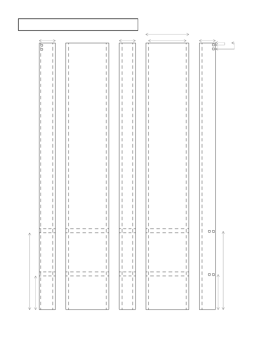
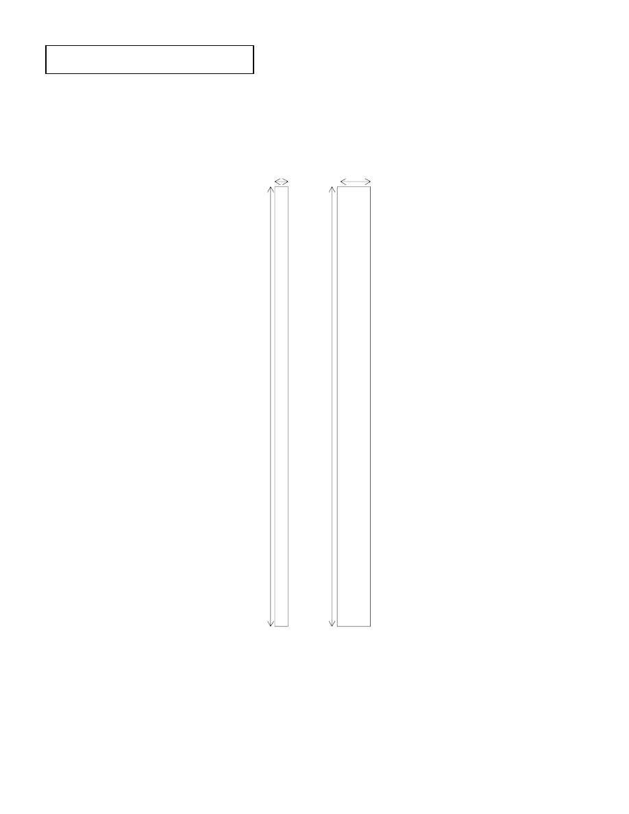
Components of Right Cabinet Side
3.0 in
8.0 in
7.0 in
3.0 in
3.0 in
6.
25 in
14
.2
5
i
n
6.
5
i
n
14.
5
i
n
0.
375
i
n
1
.125
i
n
0.
5 in
0.
5 in
3.0 in
8.0 in
7.0 in
3.0 in
3.0 in
6.
25 i
n
14
.2
5 in
6.
5
i
n
14
.5
in
0.
375 in
1.
125 in
0.
5 i
n
0.
5 i
n
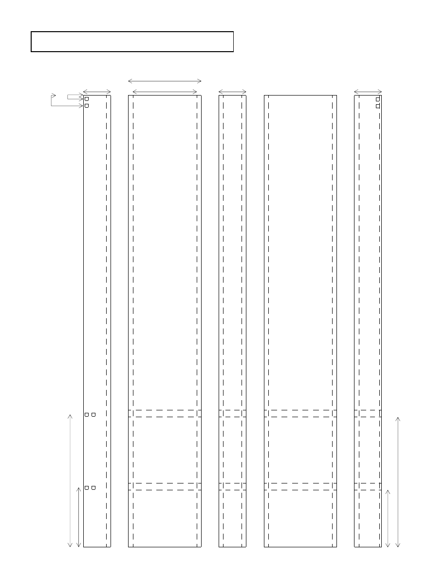
Components of Left Cabinet Side
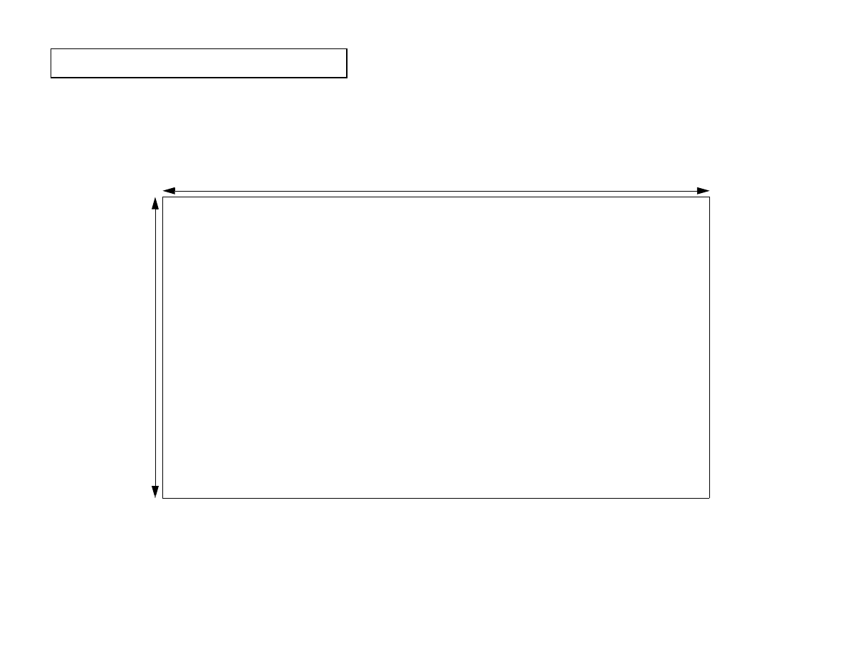
41.75 in
41.0 in
3.
0
i
n
20.
25 i
n
0.5 in
0.5 in
0.
37
5 in
Components of the Cabinet Shelves
16.0 in
14.0 in
1 in
1 in
2.
5 i
n
3.
0 in
16.0 in
14.0 in
1 in
1 in
4.
5 i
n
5.
0
i
n
33.
0 i
n
3.0 in
2.0 in
3.0 in
2.0 in
6.75 in
5.25 in
1 in
2
5
.75 in
2
4
.75 in
25.
0 i
n
Cabinet Door Assembly
Door Spacer Assembly
33.
0 in
1.0 in
33.
0 in
2.25 in
21.
75
i
n
39.5 in
Drawer Bottom
22.0 in
21.5 in
5.
75
i
n
6.
0 i
n
0.
5 in
0.
5 in
0.375 in
0.25 in
0.
25
i
n
0.
62
5
i
n
0.625 in
0.25 in
6.
0 i
n
7.
0
i
n
41.0 in
5.
37
5 i
n
39.5 in
Drawer Sides and Front
Wyszukiwarka
Podobne podstrony:
Cabinet Video Game Center (Part 1)
cabinetmakerupho00sher
Corner Cabinet 1
Plan and Install Kitchen Cabinets
bathroom cabinet szafka lazienkowa
Brydcliffe Cabinet
Display Cabinet 2
Display Cabinet 3
Atlantic E New IP66 Cabinet id Nieznany
Mobile File Cabinet
I Ogólnopolski Kongres Naukowo Szkoleniowy CABINES Polska ~Dermatologia w kosmetyce i kosmetologii~
constitution of cabinet commitee on uidai 2009
Kitchen Base Cabinet
Corner Buffet Cabinet(1)
Cabinet Compact TV Cabinet
więcej podobnych podstron