
6008V–02
–
SUPPLEMENTAL RESTRAINT SYSTEM
SUPPLEMENTAL RESTRAINT SYSTEM
60–1
2384
Author:
Date:
SUPPLEMENTAL RESTRAINT SYSTEM
PRECAUTION
CAUTION:
The CAMRY is equipped with SRS, which comprises a driver airbag, front passenger airbag,
side airbag and curtain shield airbag. Failure to carry out service operations in the correct se-
quence could cause the SRS to unexpectedly deploy during servicing, possibly leading to a
serious accident. Further, if a mistake is made in servicing the SRS, it is possible that the SRS
may fail to operate when required. Before performing servicing (including removal or installa-
tion of parts, inspection or replacement), be sure to read the following items carefully, then fol-
low the correct procedures described in the repair manual.
Work must be started 90 seconds after the ignition switch is turned to the ”LOCK” position and
the negative (–) terminal cable is disconnected from the battery.
(The SRS is equipped with a back–up power source so that if work is started within 90 seconds
from disconnecting the negative (–) terminal cable of the battery, the SRS may be deployed.)
Do not expose the horn button assy, instr pnl pass l/door airbag assy, airbag sensor assy cen-
ter, airbag front sensor, front seat airbag assy, side airbag sensor assy, curtain shield airbag
assy, airbag sensor rear or seat position airbag sensor directly to hot air or flames.
NOTICE:
Malfunction symptoms of the SRS are difficult to confirm, so the DTCs become the most impor-
tant source of information when troubleshooting. When troubleshooting the SRS, always in-
spect the DTCs before disconnecting the battery.
Even in cases of a minor collision where the SRS does not deploy, the horn button assy, instr
pnl pass l/door airbag assy, airbag sensor assy center, airbag front sensor, front seat airbag
assy, side airbag sensor assy, curtain shield airbag assy, airbag sensor rear and seat position
airbag sensor should be inspected (See page
60–9
).
Before repairs, remove the airbag sensor if shocks are likely to be applied to the sensor during
repairs.
Never use SRS parts from another vehicle. When replacing parts, replace them with new parts.
Never disassemble and repair the horn button assy, instr pnl pass l/door airbag assy, airbag
sensor assy center, airbag front sensor, front seat airbag assy, side airbag sensor assy, curtain
shield airbag assy or seat position airbag sensor in order to reuse it.
If the horn button assy, instr pnl pass l/door airbag assy, airbag sensor assy center, airbag front
sensor, front seat airbag assy, side airbag sensor assy, curtain shield airbag assy or seat posi-
tion airbag sensor has been dropped, or if there are cracks, dents or other defects in the case,
bracket or connector, replace it with new one.
Use a volt/ohmmeter with high impedance (10 k
Ω
/V minimum) for troubleshooting the system’s
electrical circuits.
Information labels are attached to the periphery of the SRS components. Follow the instruc-
tions on the notices.
After work on the SRS is completed, perform the SRS warning light check (See page
05–691
).
When the negative (–) terminal cable is disconnected from the battery, the memory of the clock
and audio system will be canceled. So before starting work, make a record of the contents mem-
orized in the audio memory system. When work is finished, reset the audio systems as they
were before and adjust the clock. To avoid erasing the memory in each memory system, never
use a back–up power supply from outside the vehicle.
If the vehicle is equipped with a mobile communication system, refer to the precaution in the
INTRODUCTION section.
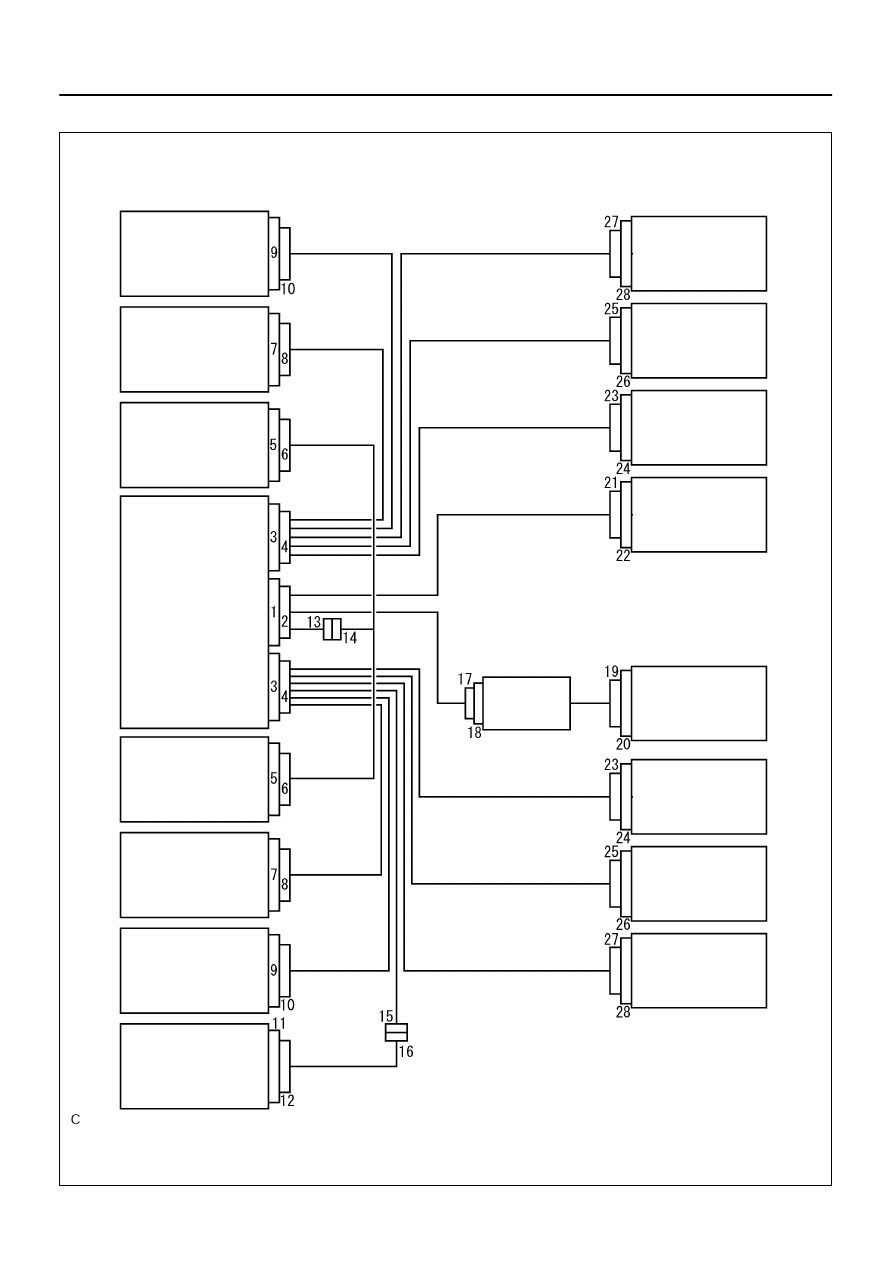
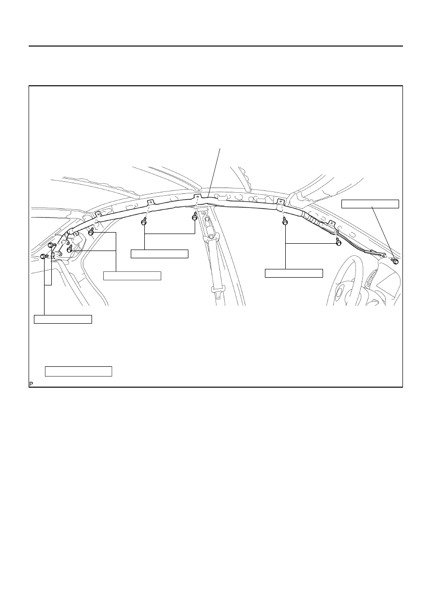
H41529
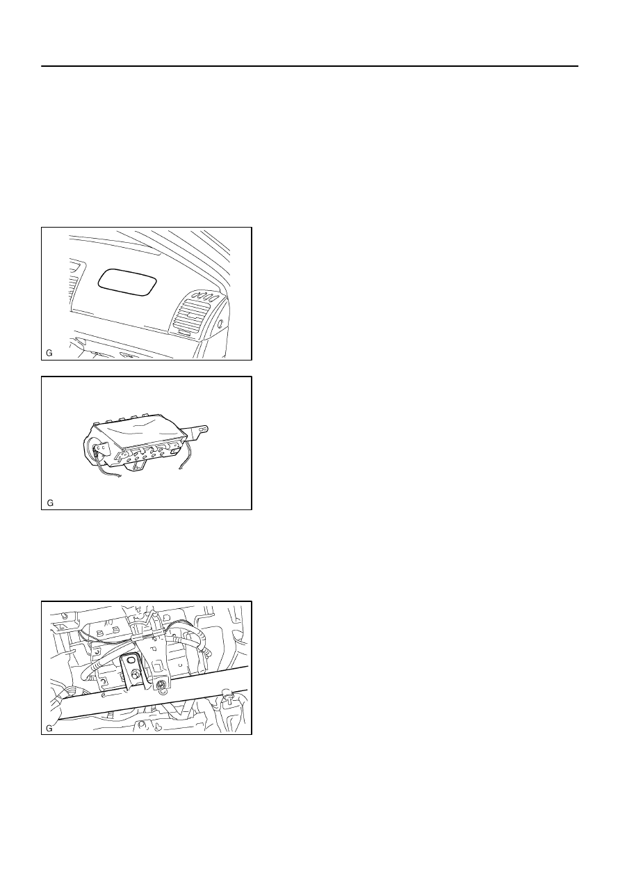
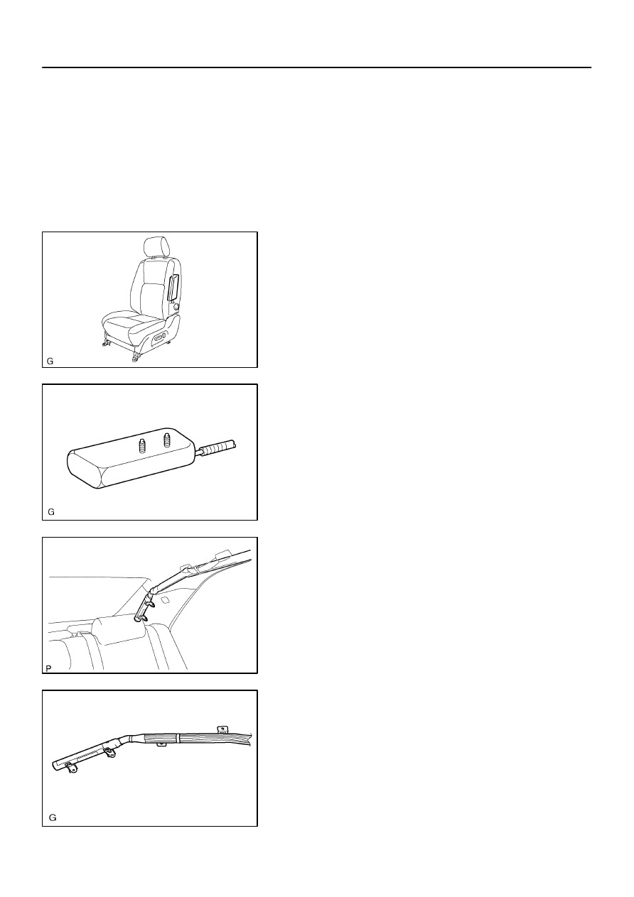
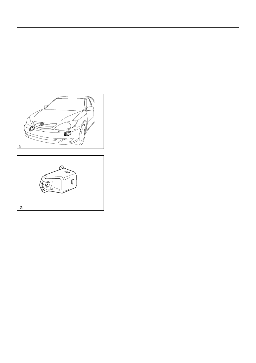
Airbag Sensor
Rear (RH)
Side Airbag
Sensor Assy (RH)
Airbag Front RH
Sensor
Airbag Sensor
Assy Center
Airbag Sensor
Front LH
Side Airbag
Sensor Assy (LH)
Airbag Sensor
Rear (LH)
Seat Position
Airbag Sensor
Spiral Cable
Sub–Assy
Horn Button Assy
(Squib)
Instr Pnl Pass
L/Door Airbag
Assy (Squib)
Curtain Shield
Airbag Assy (RH)
(Squib)
Seat Belt
Pretensioner (RH)
Front Seat
Airbag Assy (RH)
(Squib)
Front Seat
Airbag Assy (LH)
(Squib)
Seat Belt
Pretensioner (LH)
Curtain Shield
Airbag Assy (LH)
(Squib)
60–2
–
SUPPLEMENTAL RESTRAINT SYSTEM
SUPPLEMENTAL RESTRAINT SYSTEM
2385
Author:
Date:
1.
SRS CONNECTORS
Z05953
Spacer
Housing
Female
Male
R10587
When Connector is Connected
When Connector is Disconnected
Short Spring Plate
Housing
Housing
Terminal
Connectors
Short Spring Plate
Squib
Closed Circuit
Squib
Short Spring Plate ON
Contacting Male Terminal
Short Spring Plate
–
SUPPLEMENTAL RESTRAINT SYSTEM
SUPPLEMENTAL RESTRAINT SYSTEM
60–3
2386
Author:
Date:
No.
Item
Application
(1)
Terminal Twin–Lock Mechanism
Connectors 2, 4, 6, 8, 10, 12, 13, 14, 15, 16, 17, 23, 24
(2)
Airbag Activation Prevention Mechanism
Connectors 2, 4, 18, 20, 22, 24, 26, 28
(3)
Electrical Connection Check Mechanism
Connectors 1, 2, 3, 4
(4)
Half Connection Prevention Mechanism
Connectors 6, 8, 10, 14, 23
(5)
Connector Lock Mechanism
Connectors 19, 21, 25, 27
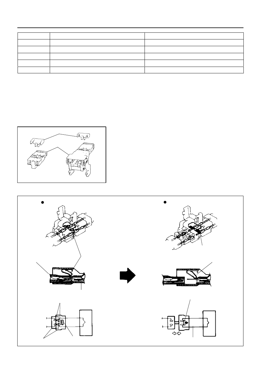
(a)
All connectors in the SRS are colored in yellow to distin-
guish them from other connectors. Connectors having
special functions and specifically designed for the SRS
are used in the locations shown on the previous page to
ensure high reliability. These connectors use durable
gold–plated terminals.
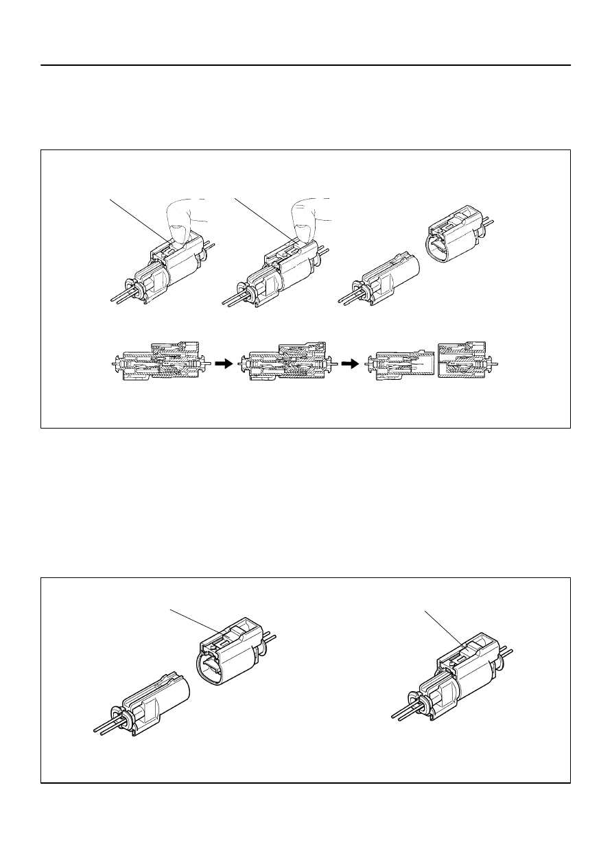
(1)
Terminal twin–lock mechanism:
Each connector has a two–piece component con-
sisting of a housing and a spacer. This design en-
ables the terminal to be locked securely by two lock-
ing devices (the retainer and the lance) to prevent
terminals from coming out.
(2)
Airbag activation prevention mechanism:
Each connector contains a short spring plate. When
the connector is disconnected, the short spring
plate automatically connects positive (+) terminal
and negative (–) terminal of the squib.
H41646
Disconnection
Detection
Pin
Airbag Sensor Assy Center
H01315
Terminal for Diagnosis
Disconnection Detection Pin
Half Connection
Complete Connection
Terminal for
Diagnosis
C51019
H40180
Stopper
Locking Part
Spring
Slider
Locking Arm
Rebounded by Slider
(Spring)
Stopper
60–4
–
SUPPLEMENTAL RESTRAINT SYSTEM
SUPPLEMENTAL RESTRAINT SYSTEM
2387
Author:
Date:
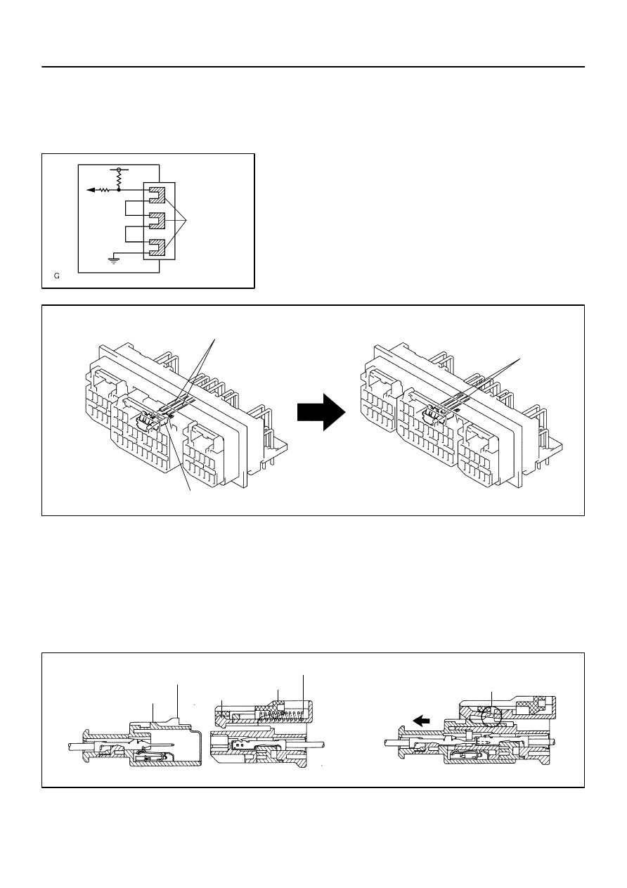
HINT:
The type of connector is shown in the diagram on the previous
page.
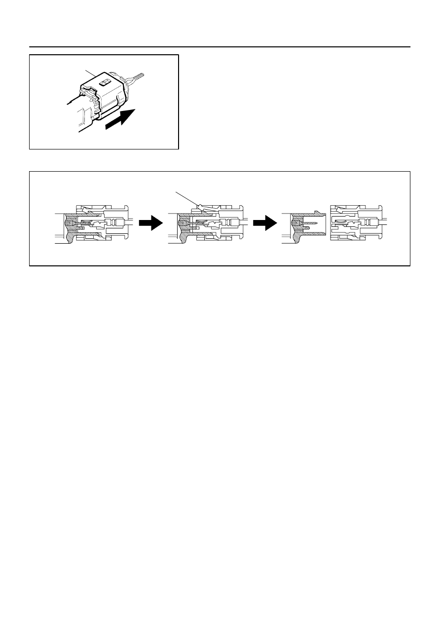
(3)
Electrical connection check mechanism:
This mechanism electrically checks that connectors
are connected correctly and completely. The electri-
cal connection check mechanism is designed so
that the disconnection detection pin connects with
the diagnosis terminals when the connector hous-
ing lock is locked.
HINT:
The connectors shown in this illustration are connectors, ”1”,
”2”, ”3” and ”4” in step 8.
(4)
Half connection prevention mechanism:
If the connector is not completely connected, the
connector is disconnected due to the spring opera-
tion to the extent that no continuity exists.
H40181
Z14034
Fig.1
Fig.2
Power Source
Safing
Sensor
Squibs
Deceleration
Sensor
–
SUPPLEMENTAL RESTRAINT SYSTEM
SUPPLEMENTAL RESTRAINT SYSTEM
60–5
2388
Author:
Date:
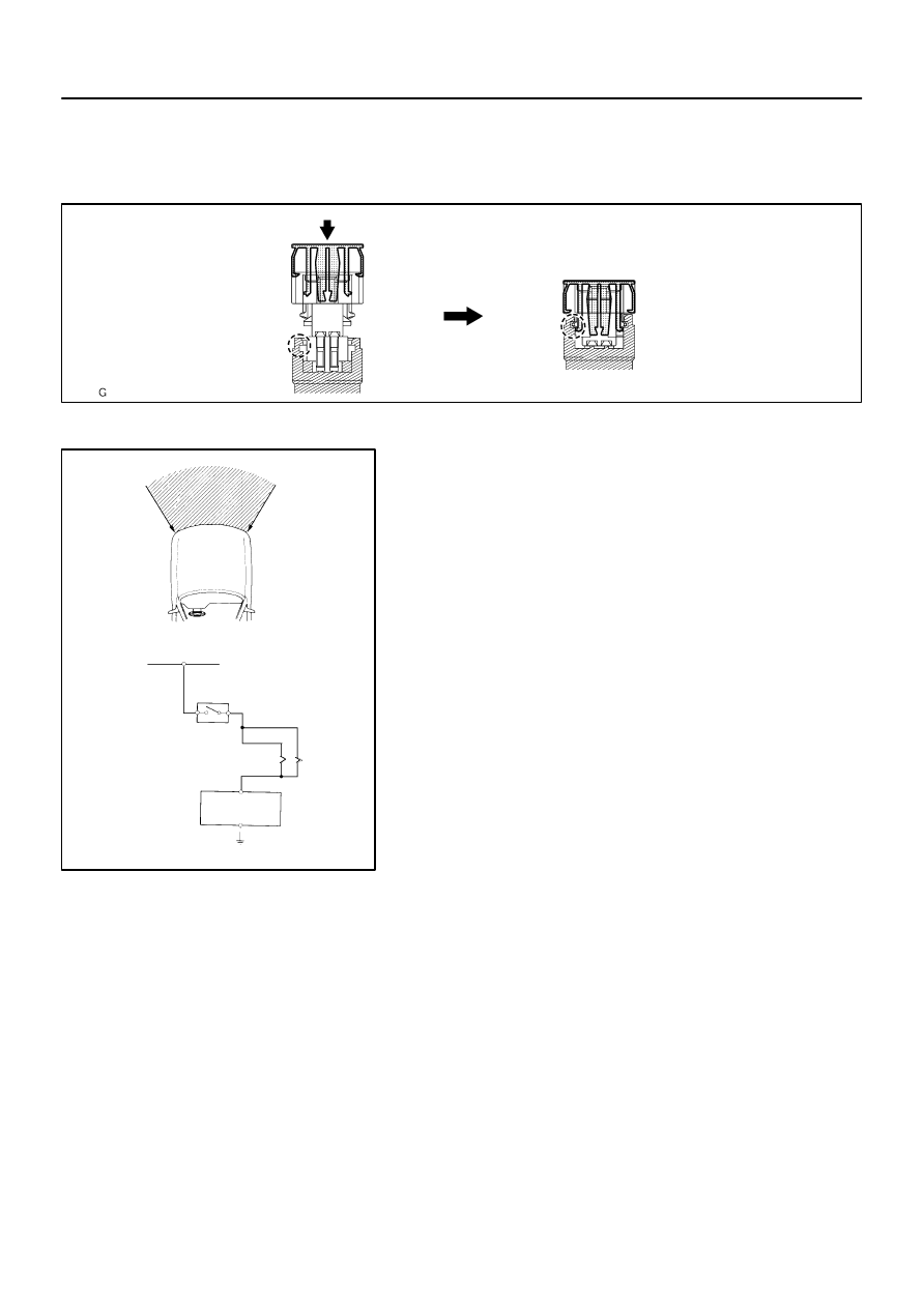
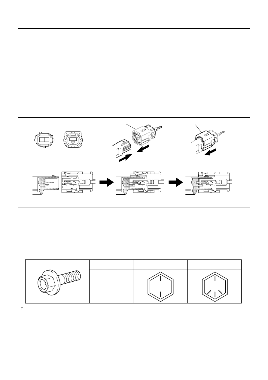
(5)
Connector lock mechanism:
Locking the connector lock button securely con-
nects the connector.
(b)
When the vehicle is involved in a frontal collision in the
hatched area (Fig. 1) and the shock is larger than the pre-
determined level, the SRS is activated automatically. A
safing sensor is designed to go on at a smaller decelera-
tion rate than the airbag sensor. As illustrated in Fig. 2,
ignition is caused when current flows to the squib, which
happens when a safing sensor and the deceleration sen-
sor go on simultaneously. When a deceleration force acts
on the sensors, 2 squibs in the driver airbag and front pas-
senger airbag ignite and generate gas. The gas discharg-
ing into the driver airbag and front passenger airbag rap-
idly increases the pressure inside the bags, breaking
open the horn button assy and instrument panel. Bag
inflation then ends, and the bags deflate as the gas is dis-
charged through discharge holes at the bag’s rear or side.
H01584
Slider
Slider
Disconnection is completed
H01585
Slider
Slider
60–6
–
SUPPLEMENTAL RESTRAINT SYSTEM
SUPPLEMENTAL RESTRAINT SYSTEM
2389
Author:
Date:
2.
DISCONNECTION OF CONNECTOR FRONT SEAT AIRBAG ASSY
(a)
Place a finger on the slider.
(b)
Slide the slider to release lock.
(c)
Disconnect the connector.
3.
CONNECTION OF CONNECTOR FOR FRONT SEAT AIRBAG ASSY
(a)
Align a lock part of male connector and a slider of female connector in the same direction as shown
in the illustration, fit in them without rubbing.
(b)
Be sure to insert until they are locked. After fitting in pull them slightly to check that they are locked.
(When locked, make sure that the outer returns to its original position and sound at the time of fitting
in can be heard.)
HINT:
As the slider slides, do not touch it.
Be careful not to deform the release board. If the release board is deformed, replace it with a new one.
H02763
Outer
H02764
Lock of connector is released
Disconnection is completed
–
SUPPLEMENTAL RESTRAINT SYSTEM
SUPPLEMENTAL RESTRAINT SYSTEM
60–7
2390
Author:
Date:
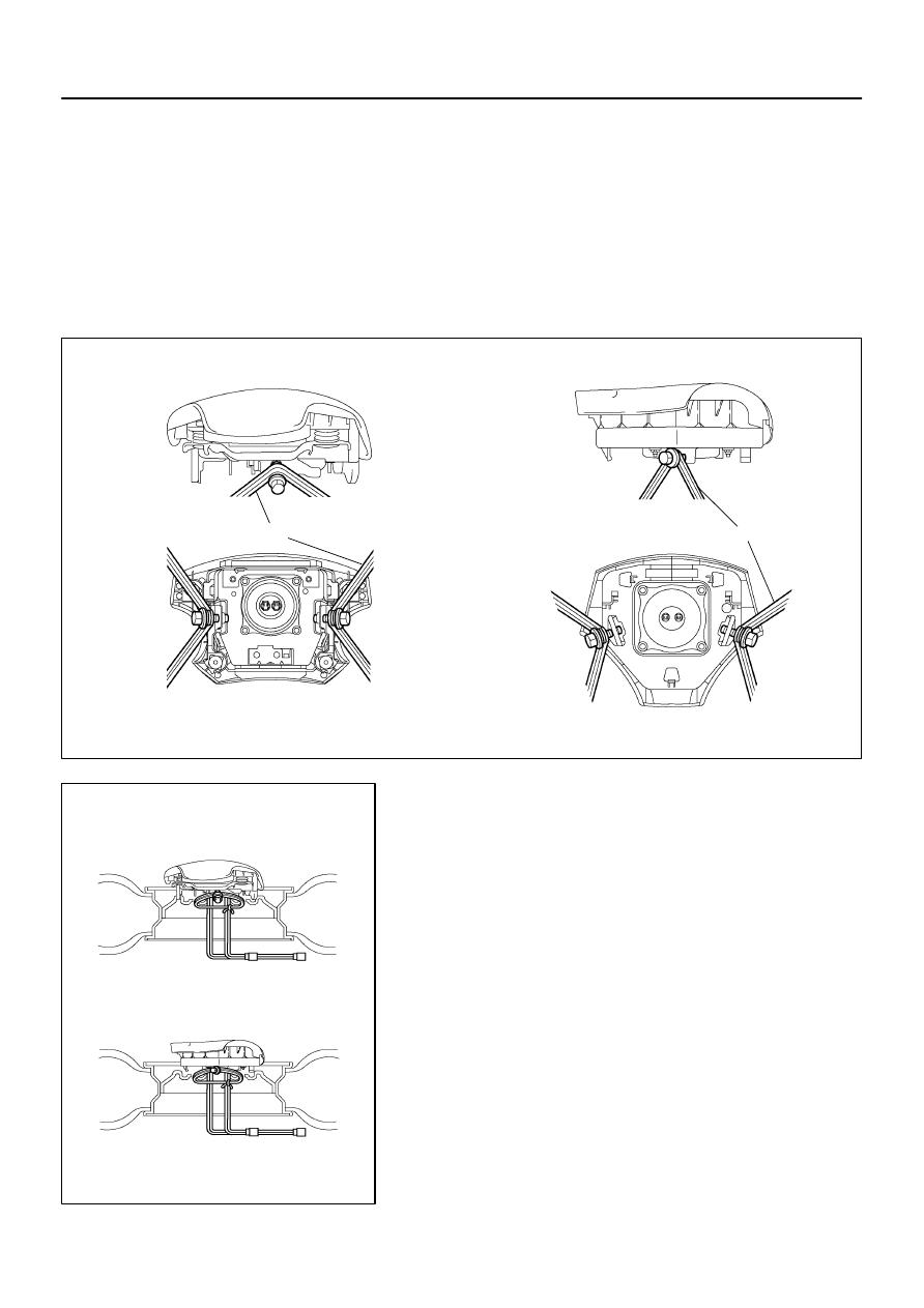
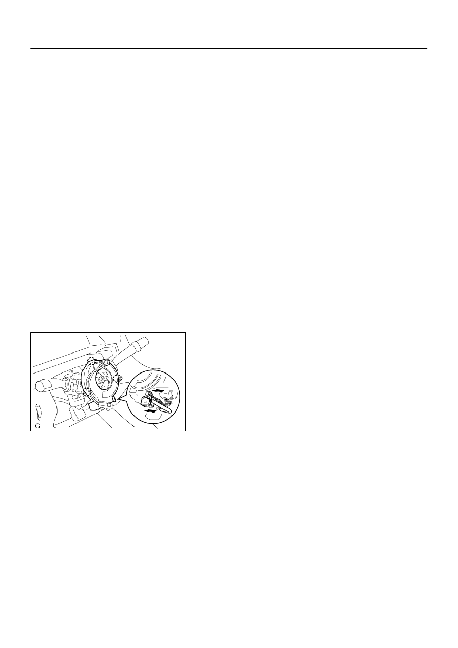
4.
DISCONNECTION OF AIRBAG FRONT SENSOR, SIDE
AIRBAG SENSOR AND AIRBAG SENSOR REAR CON-
NECTOR
(a)
While holding both flank sides of the outer, slide the outer
to the direction shown by an arrow.
(b)
Lock of the connectors is released, then disconnect the
connectors.
HINT:
Be sure to hold both flank sides of the outer. If holding the top
and bottom sides, it will obstruct disconnection.
H02768
Outer
Outer
Connection is completed
C92133
H41649
PROPERTY CLASS
Deep Recess Bolt
6T
8T
60–8
–
SUPPLEMENTAL RESTRAINT SYSTEM
SUPPLEMENTAL RESTRAINT SYSTEM
2391
Author:
Date:
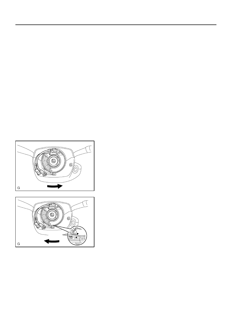
5.
CONNECTION OF CONNECTORS FOR AIRBAG FRONT SENSOR, SIDE AIRBAG SENSOR AND
AIRBAG SENSOR REAR
(a)
Align the male connector (on the side of sensor) and female connector in the same direction as shown
in the illustration and fit in them without rubbing.
(b)
As they are fitted in, the outer slides rearward. Press it until the outer returns to its original position
again.
If fitting stops half way, connectors will separate.
(c)
Be sure to insert until they are locked. After fitting in, pull them slightly to check that they are locked.
(When locked, make sure that the outer returns to its original position and sound at the time of fitting
in can be heard.)
HINT:
Do not fit in while holding the outer.
When fitting in, the outer slides. Do not touch it.
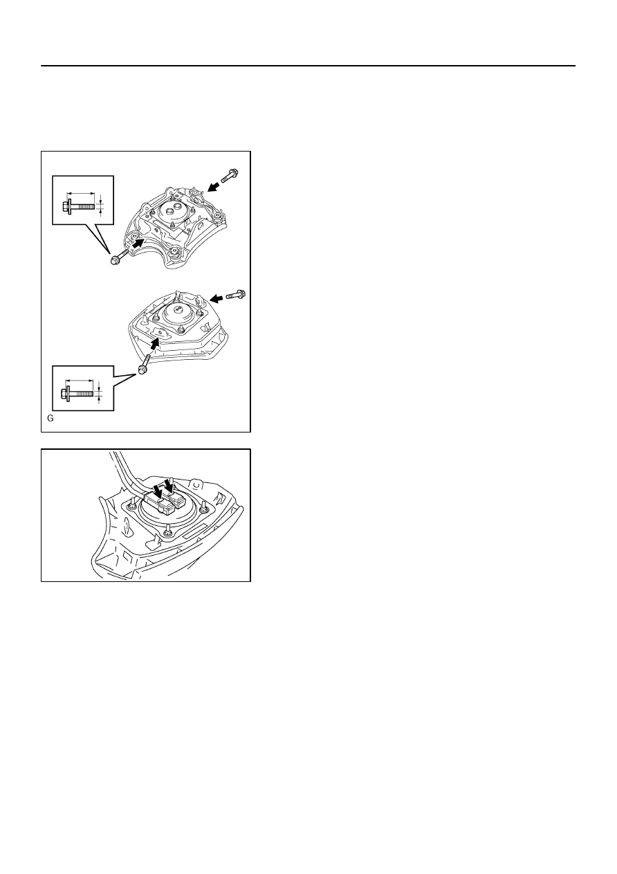
6.
NOTICE REGARDING AIRBAG SENSOR INSTALLATION BOLT
(a)
As the tightening torque is different depending on the property class of the airbag sensor installation
bolt, choose a bolt referring to the following illustration and tighten with the specified tightening torque
written in the repair manual.
6007D–01
H41101
H41102
H41395
H41639
Contact
Plate
Contact
Plate
H41397
–
SUPPLEMENTAL RESTRAINT SYSTEM
SUPPLEMENTAL RESTRAINT SYSTEM
60–9
2392
Author:
Date:
2002 CAMRY REPAIR MANUAL (RM881U)
ON–VEHICLE INSPECTION
1.
HORN BUTTON ASSY (VEHICLES NOT INVOLVED IN
COLLISION)
(a)
Do a diagnostic system check (See page
05–690
).
(b)
Do a visual check which includes the following item with
the horn button assy (with airbag) installed in the vehicle.
Check cuts, minute cracks or marked discoloration on the
horn button assy top surface and in the grooved portion.
2.
HORN BUTTON ASSY(VEHICLE INVOLVED IN COLLI-
SION AND AIRBAG IS NOT DEPLOYED)
(a)
Do a diagnostic system check (See page
05–690
).
(b)
Do a visual check which includes the following items with
the horn button assy (with airbag) removed from the ve-
hicle.
Check cuts, minute cracks or marked discoloration
on the horn button assy top surface and in the
grooved portion.
Check cuts and cracks in wire harness, and chip-
ping in connectors.
Check the deformation on the steering wheel.
Check the deformation on the horn button contact
plate of the horn button assy.
HINT:
If the horn button contact plate of the horn button assy is
deformed, never repair it. Always replace the horn button
assy with a new one.
There should be no interference between the horn button
assy and steering wheel, and the clearance should be
uniform all the way around when the new horn button
assy is installed on the steering wheel.
CAUTION:
For removal and installation of the horn button assy, see
page
60–15
, and be sure to follow the correct procedure.
H41398
H41432
H41399
60–10
–
SUPPLEMENTAL RESTRAINT SYSTEM
SUPPLEMENTAL RESTRAINT SYSTEM
2393
Author:
Date:
2002 CAMRY REPAIR MANUAL (RM881U)
3.
HORN BUTTON ASSY(VEHICLE INVOLVED IN COLLISION AND AIRBAG IS DEPLOYED)
(a)
Do a diagnostic system check (See page
05–690
).
(b)
Do a visual check which includes the following item with the horn button assy (with airbag) removed
from the vehicle.
Check the damage on the spiral cable connector and wire harness.
HINT:
There should be no interference between the horn button assy and steering wheel, and the clearance should
be uniform all the way around when the new horn button assy is installed on the steering wheel.
4.
INSTR PNL PASS L/DOOR AIRBAG ASSY(VEHICLE
NOT INVOLVED IN COLLISION)
(a)
Do a diagnostic system check (See page
05–690
).
(b)
Do a visual check which includes the following item with
the instr pnl pass l/door airbag assy installed in the ve-
hicle.
Check cuts, minute cracks or marked discoloration on the
instr pnl pass l/door airbag assy and instrument panel.
5.
INSTR PNL PASS L/DOOR AIRBAG ASSY(VEHICLE
INVOLVED IN COLLISION AND AIRBAG IS NOT
DEPLOYED)
(a)
Do a diagnostic system check (See page
05–690
).
(b)
Do a visual check which includes the following items with
the instr pnl pass l/door airbag assy removed from the ve-
hicle.
Check cuts, minute cracks or marked discoloration
on the instr pnl pass l/door airbag assy.
Check cuts and cracks in wire harness, and for chip-
ping in connectors.
Check the deformation or cracks on the instrument
panel and instrument panel reinforcement.
HINT:
If the instrument panel or instrument panel reinforcement is de-
formed or cracked, never repair it. Always replace it with a new
one.
CAUTION:
For removal and installation of the instrument panel pas-
senger airbag assy, see page
60–30
, and be sure to follow
the correct procedure.
H41400
H41401
C92094
H41402
–
SUPPLEMENTAL RESTRAINT SYSTEM
SUPPLEMENTAL RESTRAINT SYSTEM
60–11
2394
Author:
Date:
2002 CAMRY REPAIR MANUAL (RM881U)
6.
INSTR PNL PASS L/DOOR AIRBAG ASSY(VEHICLE INVOLVED IN COLLISION AND AIRBAG IS
DEPLOYED)
(a)
Do a diagnostic system check (See page
05–690
).
(b)
Do a visual check which includes the following items with the instr pnl pass l/door airbag assy removed
from the vehicle.
Check the deformation or cracks on the instrument panel and instrument panel reinforcement.
Check the damage on the connector and wire harness.
HINT:
If the instrument panel or instrument panel reinforcement is deformed or cracked, never repair it. Always
replace it with a new one.
7.
FRONT SEAT AIRBAG ASSY(VEHICLE NOT IN-
VOLVED IN COLLISION)
(a)
Do a diagnostic system check (See page
05–690
).
(b)
Do a visual check which includes the following item with
the front seat airbag assy installed in the vehicle.
Check cuts, minute cracks or marked discoloration on the
front passenger airbag assy and instrument panel.
8.
FRONT SEAT AIRBAG ASSY(VEHICLE INVOLVED IN
COLLISION AND AIRBAG IS NOT DEPLOYED)
(a)
Do a diagnostic system check (See page
05–690
).
(b)
Do a visual check which includes the following items with
the front seat airbag assy removed from the vehicle.
Check cuts, minute cracks or marked discoloration
on the front seat airbag assy.
Check cuts and cracks in wire harness, and for chip-
ping in connectors.
9.
CURTAIN SHIELD AIRBAG ASSY (VEHICLE NOT IN-
VOLVED IN COLLISION)
(a)
Do a diagnostic system check (See page
05–690
).
(b)
Do a visual check which includes the following item with
the curtain shield airbag assy installed in the vehicle.
Check cuts, minute cracks or marked discoloration on the
curtain shield airbag assy.
10.
CURTAIN SHIELD AIRBAG ASSY (VEHICLE IN-
VOLVED IN COLLISION AND AIRBAG IS NOT
DEPLOYED)
(a)
Do a diagnostic system check (See page
05–690
).
(b)
Do a visual check which includes the following items with
the curtain shield airbag assy removed from the vehicle.
Check cuts, minute cracks or marked discoloration
on the curtain shield airbag assy.
Check cuts and cracks in wire harness, and for chip-
ping in connectors.
C93732
H41404
60–12
–
SUPPLEMENTAL RESTRAINT SYSTEM
SUPPLEMENTAL RESTRAINT SYSTEM
2395
Author:
Date:
2002 CAMRY REPAIR MANUAL (RM881U)
11.
AIRBAG SENSOR ASSY CENTER(VEHICLE NOT INVOLVED IN COLLISION)
(a)
Do a diagnostic system check (See page
05–690
).
12.
AIRBAG SENSOR ASSY CENTER(VEHICLE INVOLVED IN COLLISION AND AIRBAG IS NOT
DEPLOYED)
(a)
Do a diagnostic system check (See page
05–690
).
13.
AIRBAG SENSOR ASSY CENTER(VEHICLE INVOLVED IN COLLISION AND AIRBAG IS
DEPLOYED)
(a)
Replace the airbag sensor assy center (See page
60–56
).
14.
AIRBAG FRONT SENSOR(VEHICLE NOT INVOLVED
IN COLLISION)
(a)
Do a diagnostic system check (See page
05–690
).
15.
AIRBAG FRONT SENSOR(VEHICLE INVOLVED IN
COLLISION)
(a)
Do a diagnostic system check (See page
05–690
).
(b)
If the front fender of the car or its periphery is damaged,
do a visual check for damage to the airbag front sensor,
which includes the following items even if the airbag was
not deployed:
Cracks, dents or chips in the case
Cracks, dents, chipping and scratches in the con-
nector
Peeling off of the label or damage to the serial num-
ber
16.
SIDE AIRBAG SENSOR ASSY(VEHICLE NOT INVOLVED IN COLLISION)
(a)
Do a diagnostic system check (See page
05–690
).
17.
SIDE AIRBAG SENSOR ASSY(VEHICLE INVOLVED IN COLLISION AND AIRBAG IS NOT
DEPLOYED)
(a)
Do a diagnostic system check (See page
05–690
).
18.
SIDE AIRBAG SENSOR ASSY(VEHICLE INVOLVED IN COLLISION AND AIRBAG IS DEPLOYED)
(a)
Replace the front seat airbag assy and side airbag sensor assy (See page
60–62
,
72–7
).
19.
AIRBAG SENSOR REAR(VEHICLE NOT INVOLVED IN COLLISION)
(a)
Do a diagnostic system check (See page
05–690
).
20.
AIRBAG SENSOR REAR(VEHICLE INVOLVED IN COLLISION AND AIRBAG IS NOT DEPLOYED)
(a)
Do a diagnostic system check (See page
05–690
).
21.
AIRBAG SENSOR REAR(VEHICLE INVOLVED IN COLLISION AND AIRBAG IS DEPLOYED)
(a)
Replace the curtain shield airbag assy and airbag sensor rear (See page
60–41
,
60–65
).

–
SUPPLEMENTAL RESTRAINT SYSTEM
SUPPLEMENTAL RESTRAINT SYSTEM
60–13
2396
Author:
Date:
2002 CAMRY REPAIR MANUAL (RM881U)
22.
SEAT POSITION SENSOR(VEHICLES NOT INVOLVED IN COLLISION)
(a)
Do a diagnostic system check (See page
05–690
).
23.
SEAT POSITION SENSOR(VEHICLE INVOLVED IN COLLISION)
(a)
Do a diagnostic system check (See page
05–690
).
(b)
Do a visual check for damage to the airbag front sensor, which includes the following items even if the
airbag was not deployed:
Cracks, dents or chips in the case
Cracks, dents, chipping and scratches in the connector
24.
WIRE HARNESS AND CONNECTOR(VEHICLE NOT INVOLVED IN COLLISION)
Do a diagnostic system check (See page
05–690
).
25.
WIRE HARNESS AND CONNECTOR(VEHICLE INVOLVED IN COLLISION)
(a)
Do a diagnostic system check (See page
05–690
).
(b)
Check breaks in all wires of the SRS wire harness, and exposed conductors.
(c)
Check to see if the SRS wire harness connectors are cracked or chipped.
HINT:
The SRS wire harness is integrated with the instrument panel wire harness assembly. All the connectors in
the system are a standard yellow color.
6007E–01
H41405
H41427
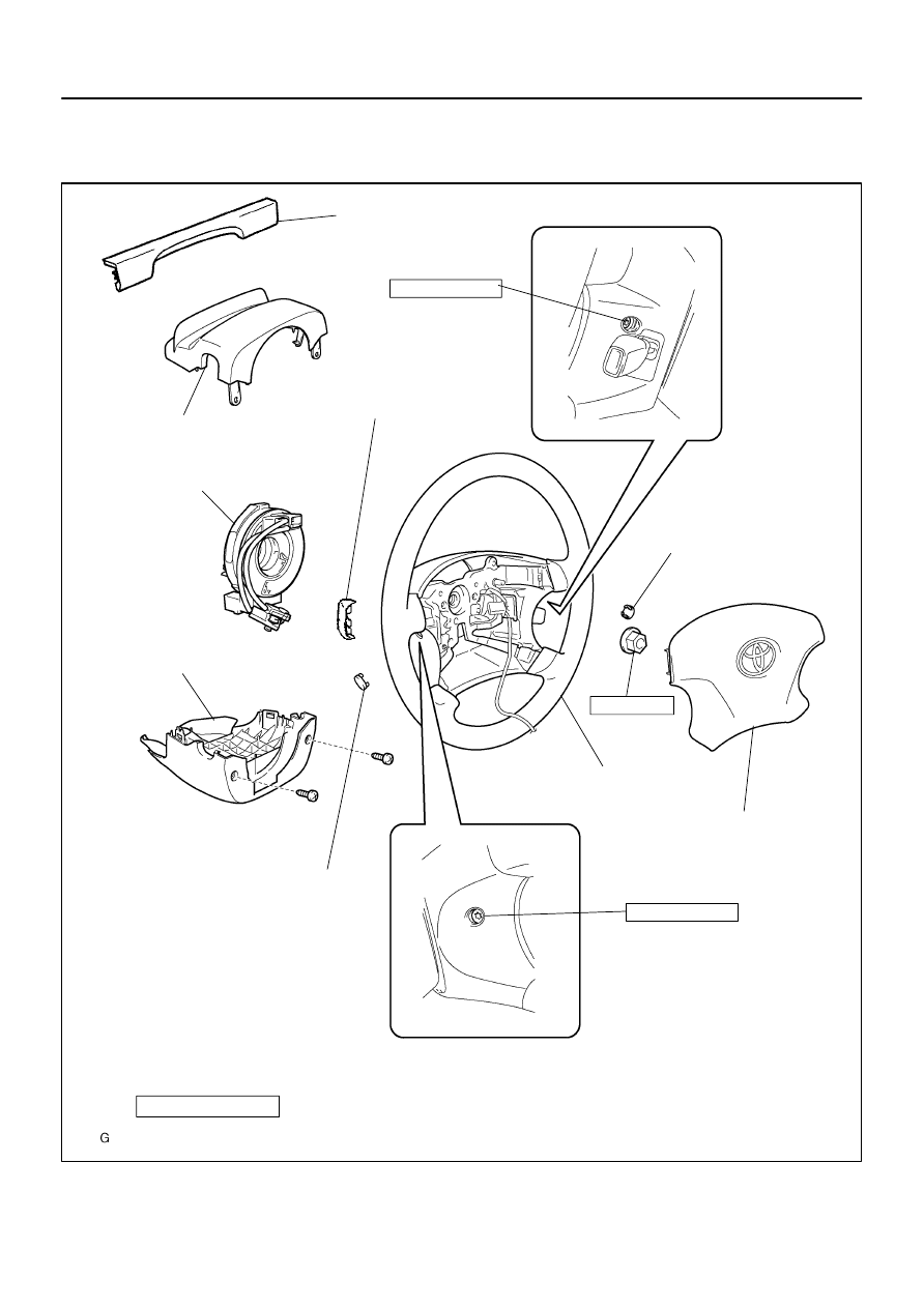
Steering Wheel Cover
Lower No. 2
Steering Wheel Assy
Horn Button Assy
Instrument Cluster Finish Panel
Steering Column Cover
w/ Steering Pad Switch:
Connector Cover
Spiral Cable Sub–Assy
Steering Column Cover
Steering Wheel Cover Lower No. 2
8.8 (90, 78 in.
⋅
lbf)
8.8 (90, 78 in.
⋅
lbf)
50 (510, 37)
N
⋅
m (kgf
⋅
cm, ft
⋅
lbf) : Specified torque
Steering Wheel Cover Lower No. 3
4 Spoke Steering Wheel Assy:
3 Spoke Steering Wheel Assy:
60–14
–
SUPPLEMENTAL RESTRAINT SYSTEM
HORN BUTTON ASSY
2397
Author:
Date:
2002 CAMRY REPAIR MANUAL (RM881U)
HORN BUTTON ASSY
COMPONENTS
6007F–01
H41406
4 Spoke Steering Wheel Assy:
3 Spoke Steering Wheel Assy:
H41407
4 Spoke Steering Wheel Assy:
3 Spoke Steering Wheel Assy:
–
SUPPLEMENTAL RESTRAINT SYSTEM
HORN BUTTON ASSY
60–15
2398
Author:
Date:
2002 CAMRY REPAIR MANUAL (RM881U)
REPLACEMENT
HINT:
COMPONENTS: See page
60–14
1.
PRECAUTION(See page
60–1
)
2.
SEPARATE BATTERY NEGATIVE TERMINAL(See page
60–1
)
3.
REMOVE STEERING WHEEL COVER LOWER NO.2
4.
REMOVE STEERING WHEEL COVER LOWER NO.2
(W/O STEERING PAD SWITCH 4 SPOKE STEERING
WHEEL)
5.
REMOVE STEERING WHEEL COVER LOWER NO.3(3
SPOKE STEERING WHEEL ASSY)
6.
REMOVE CONNECTOR COVER (W/ STEERING PAD
SWITCH 4 SPOKE STEERING WHEEL)
7.
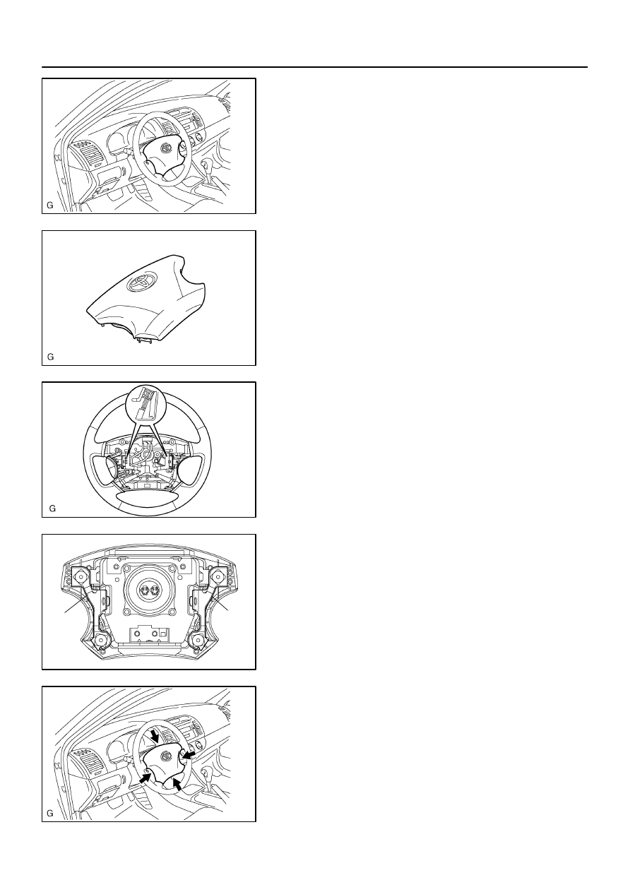
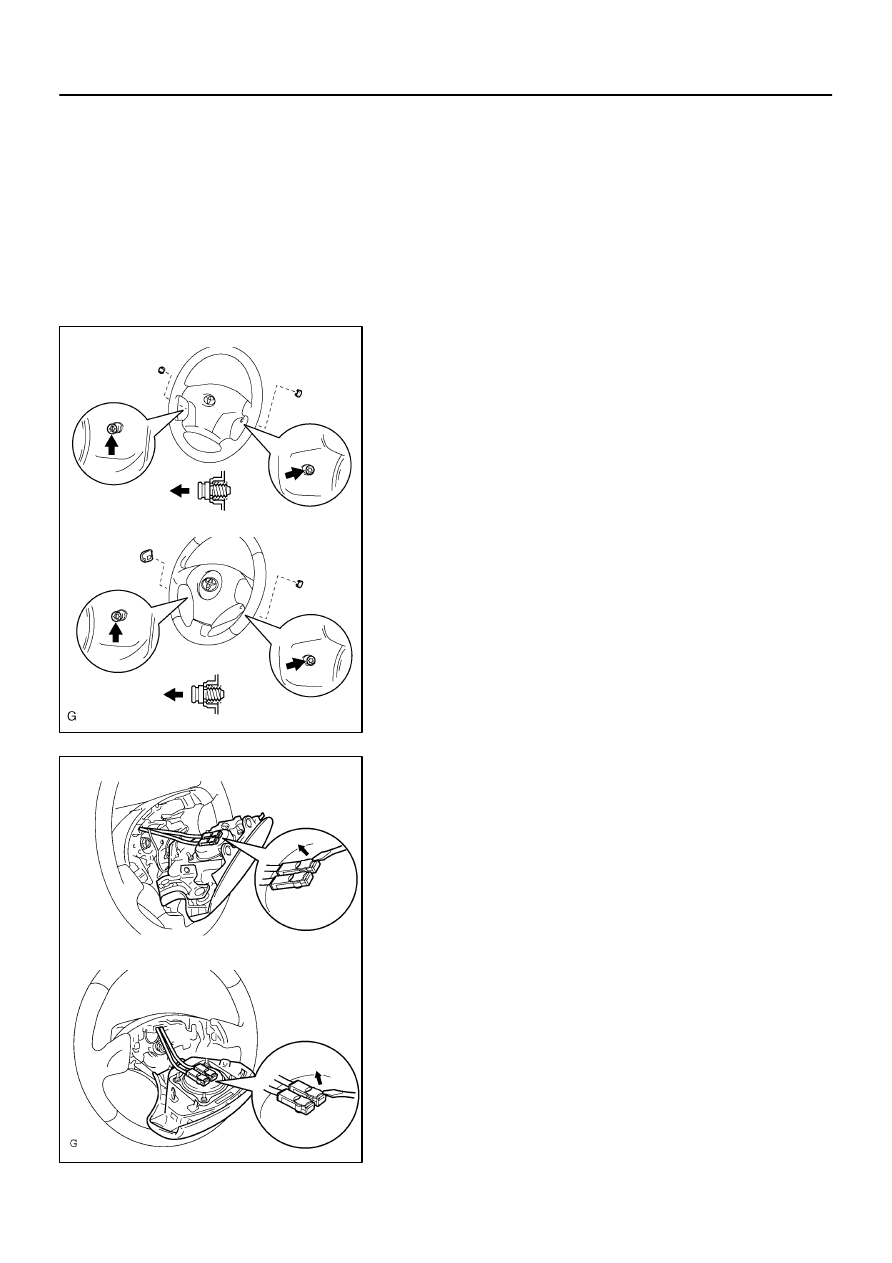
REMOVE HORN BUTTON ASSY
(a)
Place the front wheels facing straight ahead.
(b)
Using a torx socket wrench (T30), loosen the 2 torx
screws until the groove along the screw circumference
catches on the screw case.
(c)
Pull out the wheel pad from the horn button assy.
(d)
4 spoke steering wheel assy:
Disconnect the airbag connectors and horn connector
and remove the horn button assy.
(e)
3 spoke steering wheel assy:
Disconnect the airbag connectors and remove the horn
button assy.

60–16
–
SUPPLEMENTAL RESTRAINT SYSTEM
HORN BUTTON ASSY
2399
Author:
Date:
2002 CAMRY REPAIR MANUAL (RM881U)
8.
INSPECT HORN BUTTON ASSY
(See page
60–9
)
9.
INSTALL HORN BUTTON ASSY
(a)
Connect the airbag connectors and horn connector.
(b)
Install the horn button after confirming that the circumference groove of the torx screws is caught on
the screw case.
(c)
Using a torx socket wrench (T 30), install the 2 screws.
Torque: 8.8 N
⋅
m (90 kgf
⋅
cm, 78 in.
⋅
lbf)
10.
INSPECT SRS WARNING LIGHT(See page
05–690
)
6007G–01
H40004
SST
H40005
SST
Battery
H40004
SST
–
SUPPLEMENTAL RESTRAINT SYSTEM
HORN BUTTON ASSY
60–17
2400
Author:
Date:
2002 CAMRY REPAIR MANUAL (RM881U)
DISPOSAL
HINT:
When scrapping vehicle equipped with an SRS or disposing of a horn button assy, always first deploy the
airbag in accordance with the procedure described below. If any abnormality occurs with the airbag deploy-
ment, contact the SERVICE DEPT. of TOYOTA MOTOR SALES, U.S.A., INC.
CAUTION:
Never dispose of a horn button assy which has an un-
deployed airbag.
The airbag produces a sizeable exploding sound
when it deploys, so perform the operation out–of–
doors and where it will not create a nuisance to
nearby residents.
When deploying the airbag, always use the specified
SST (SRS Airbag Deployment Tool). Perform the op-
eration in a place away from electrical noise.
When deploying an airbag, perform the operation at
least 10 m (33 ft) away from the horn button assy.
The horn button assy is very hot when the airbag is
deployed, so leave it alone for at least 30 minutes af-
ter deployment.
Use gloves and safety glasses when handling a horn
button assy with the deployed airbag.
Always wash your hands with water after completing
the operation.
Do not apply water, etc. to a horn button assy with the
deployed airbag.
1.
DISPOSE HORN BUTTON ASSY(WHEN SCRAPPING
VEHICLE DEPLOYMENT METHOD)
HINT:
Have a battery ready as the power source to deploy the airbag.
(a)
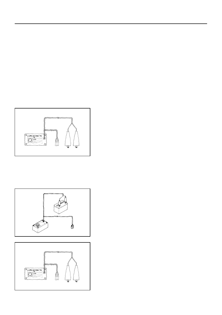
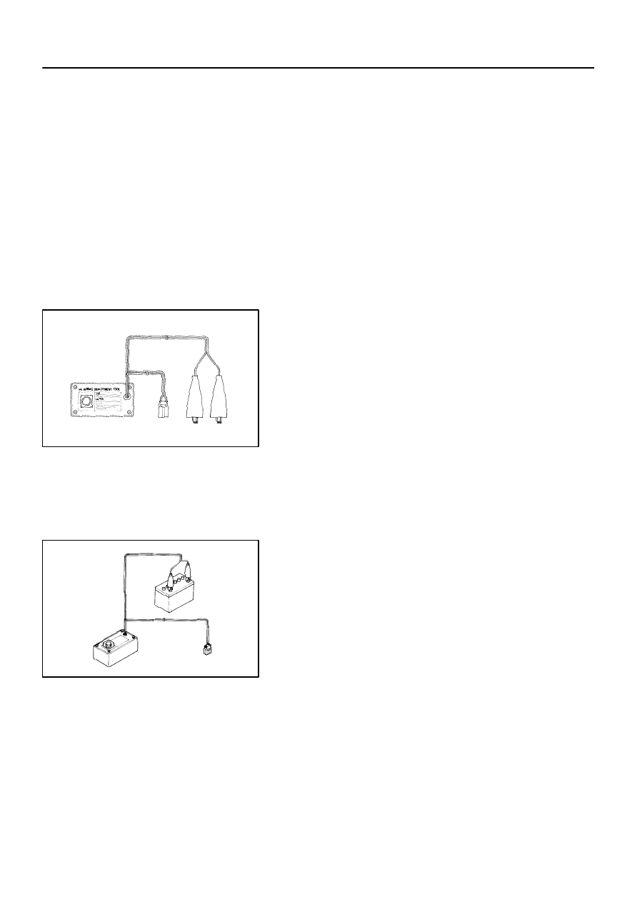
Check functioning of the SST.
CAUTION:
When deploying the airbag, always use the specified SST:
SRS Airbag Deployment Tool.
SST
09082–00700
H40005
SST
Battery
H40006
SST
H41408
H41409
SST
H40007
10 m (33 ft) or more
SST
Battery
60–18
–
SUPPLEMENTAL RESTRAINT SYSTEM
HORN BUTTON ASSY
2401
Author:
Date:
2002 CAMRY REPAIR MANUAL (RM881U)
(1)
Connect the SST to the battery.
Connect the red clip of the SST to the battery posi-
tive (+) terminal and the black clip to the battery neg-
ative (–) terminal.
HINT:
Do not connect the yellow connector which will be connected
with the supplemental restraint system.
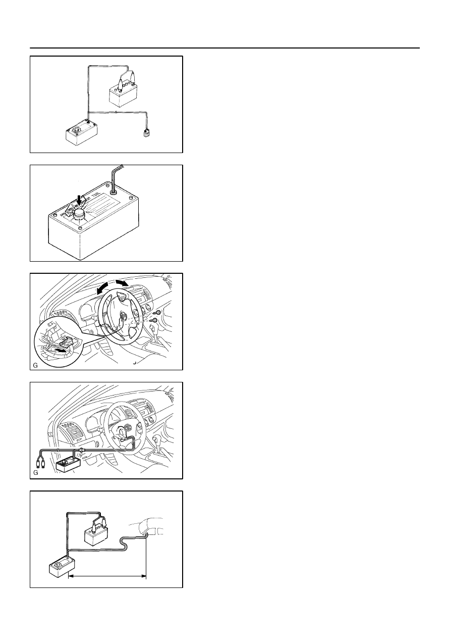
(2)
Check functioning of the SST.
Press the SST activation switch, and check that the
LED of the SST activation switch lights up.
CAUTION:
If the LED lights up when the activation switch is not being
pressed, SST malfunction is probable, so definitely do not
use the SST.
(3)
Disconnect the SST from the battery.
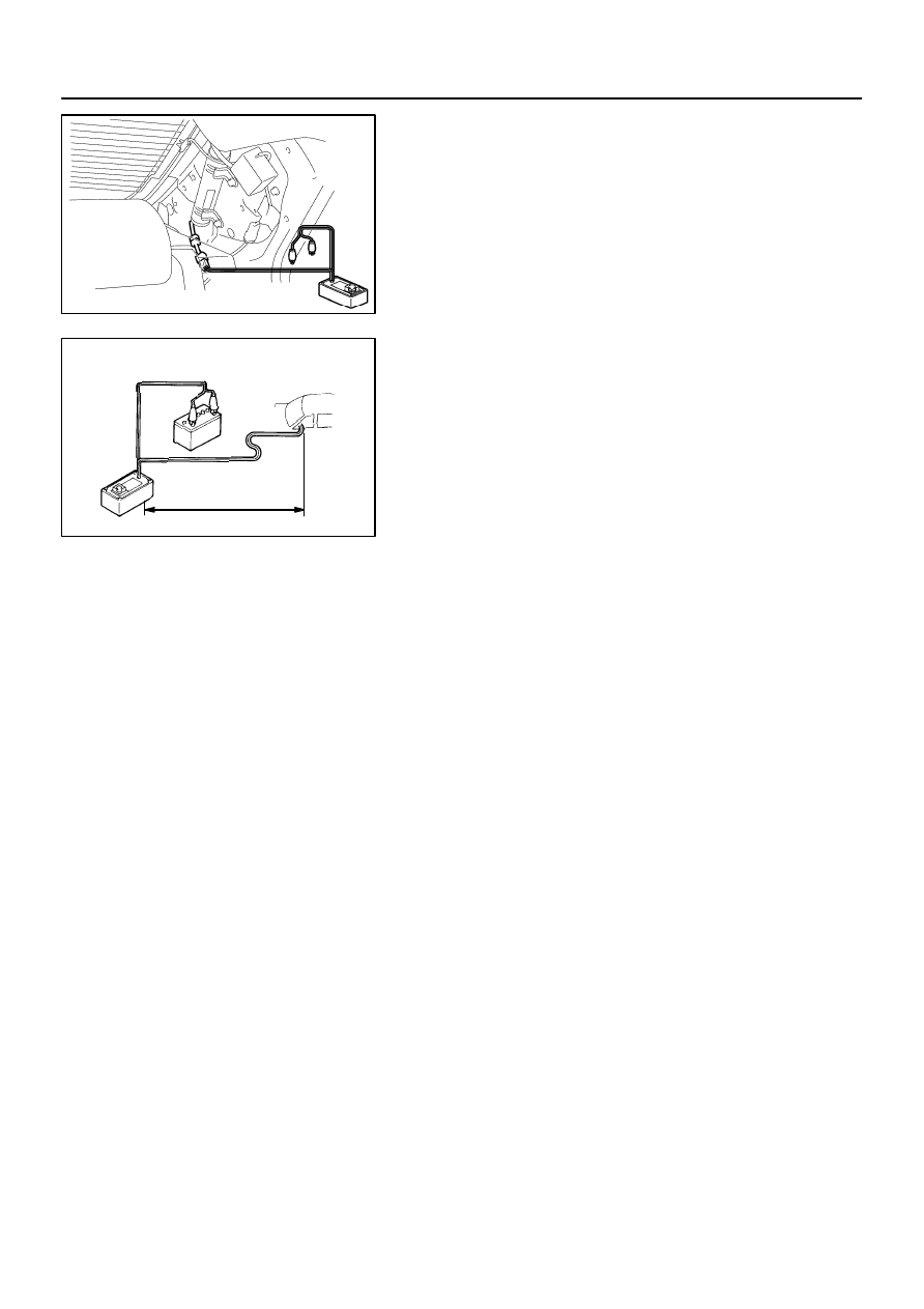
(b)
Install the SST.
CAUTION:
Check that there is no looseness in the steering wheel and
horn button assy.
(1)
While turning the steering wheel right / left, remove
the 2 screws and column lower cover.
(2)
Disconnect the airbag connector of the spiral cable.
(3)
Connect the connectors of the 2 SST to the airbag
connector of the spiral cable back side.
SST
09082–00700, 09082–00780
(4)
Move the SST at least 10 m (33 ft) away from the
front of the vehicle.
(5)
Close all the doors and windows of the vehicle.
NOTICE:
Take care not to damage the SST wire harness.
(6)
Connect the red clip of the SST to the battery posi-
tive (+) terminal and the black clip to the negative (–)
terminal.
H40008
Wire Harness
Diameter
Stripped Wire Harness Section
–
SUPPLEMENTAL RESTRAINT SYSTEM
HORN BUTTON ASSY
60–19
2402
Author:
Date:
2002 CAMRY REPAIR MANUAL (RM881U)
(c)
Deploy the airbag.
(1)
Confirm that no one is inside the vehicle or within 10
m (33 ft) area around the vehicle.
(2)
Press the SST activation switch and deploy the air-
bag.
HINT:
The airbag deploys simultaneously as the LED of the SST ac-
tivation switch lights up.
(d)
Dispose the horn button assy (with airbag).
CAUTION:
The horn button assy is very hot when the airbag is
deployed, so leave it alone for at least 30 minutes af-
ter deployment.
Use gloves and safety glasses when handling a horn
button assy with the deployed airbag.
When moving a vehicle for scrapping which has a
horn button assy with deployed airbag, use gloves
and safety glasses.
Do not apply water, etc. to a horn button assy with the
deployed airbag.
Always wash your hands with water after completing
the operation.
HINT:
When scrapping a vehicle, deploy the airbag and scrap the ve-
hicle with the horn button assy still installed.
2.
DISPOSE HORN BUTTON ASSY(WHEN DISPOSING
OF AIRBAG ASSEMBLY DEPLOYMENT METHOD)
NOTICE:
When disposing of the horn button assy (with airbag)
only, never use the customers vehicle to deploy the
airbag.
Be sure to follow the procedure given below when de-
ploying the airbag.
HINT:
Have a battery ready as the power source to deploy the airbag.
(a)
Remove the horn button assy (See page
60–15
).
CAUTION:
When storing the horn button assy, keep the upper surface
of the pad facing upward.
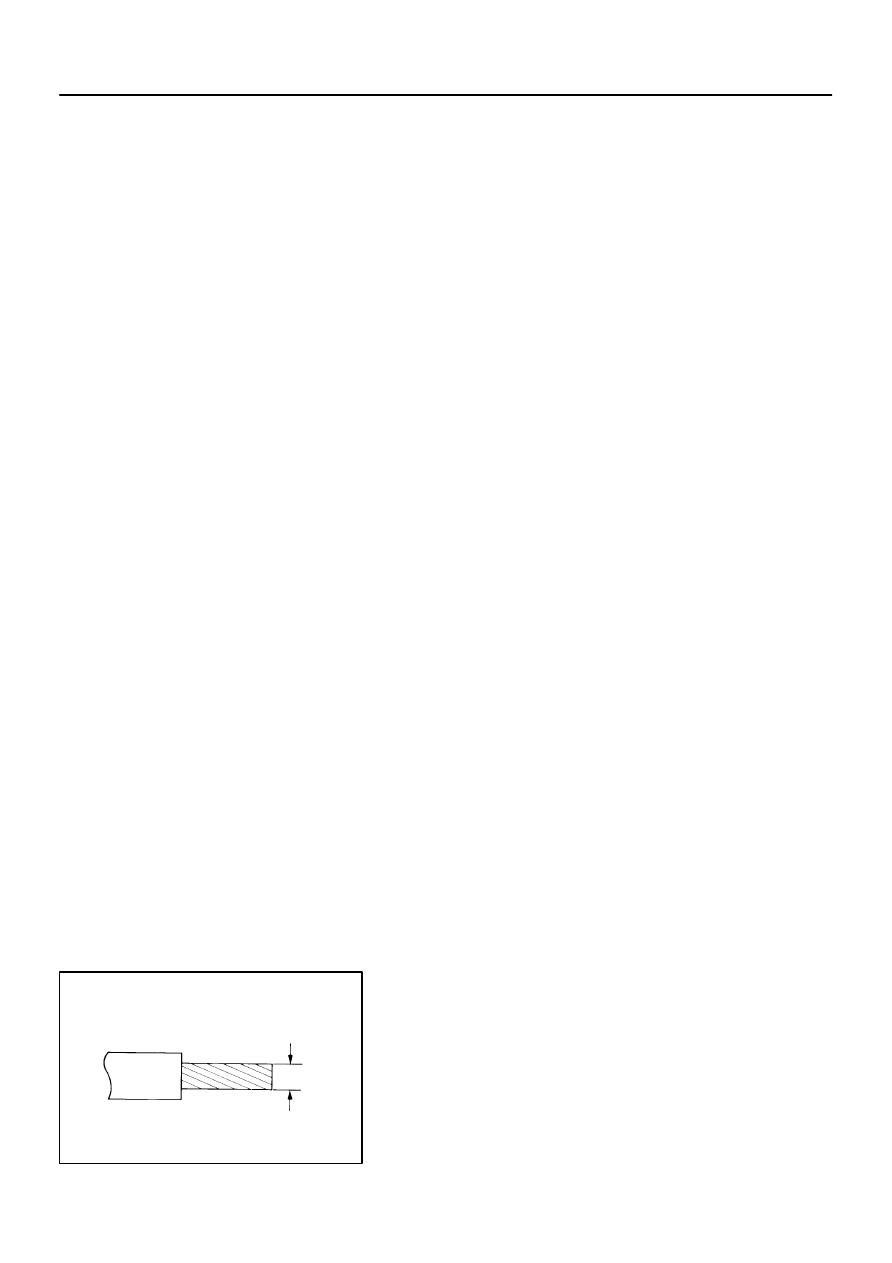
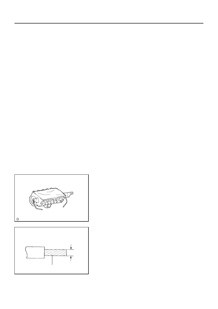
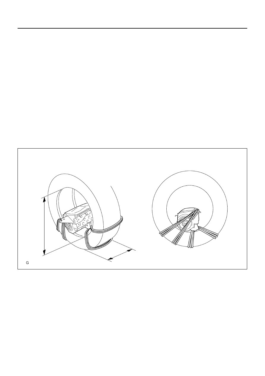
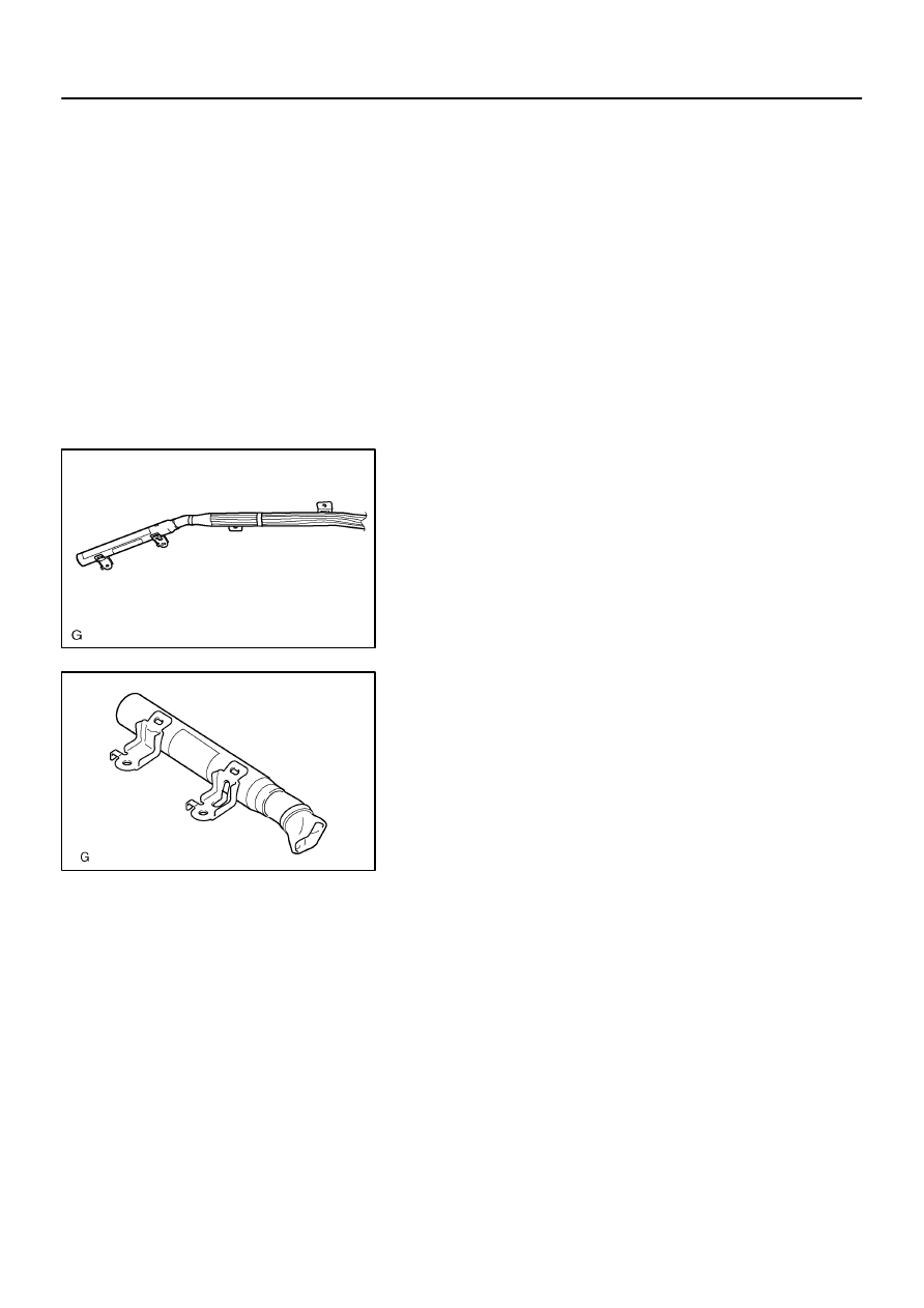
(b)
Using a service–purpose wire harness for the vehicle, tie
down the horn button assy to the disc wheel.
Wire harness: Stripped wire harness section
1.25 mm
2
or more (0.0019 in
2
. or more)
CAUTION:
If a wire harness which is too thin or some other thing is
used to tie down the horn button assy, it may be snapped
by the shock when the airbag is deployed. This is highly
dangerous. Always use a wire harness for vehicle use
which is at least 1.25 mm
2
(0.0019 in
2
).
H41410
L
M
L
M
4 Spoke Steering Wheel Assy:
3 Spoke Steering Wheel Assy:
C93770
60–20
–
SUPPLEMENTAL RESTRAINT SYSTEM
HORN BUTTON ASSY
2403
Author:
Date:
2002 CAMRY REPAIR MANUAL (RM881U)
HINT:
To calculate the square of the stripped wire harness section:
Square = 3.14 x (Diameter)
2
divided by 4
(1)
Install the 2 bolts with washers in the 2 bolt holes in
the horn button assy.
Bolt:
L: 35.0 mm (1.387 in.)
M: 6.0 mm (0.236 in.)
Pitch: 1.0 mm (0.039 in.)
NOTICE:
Tighten the bolts by hand until the bolts become diffi-
cult to turn.
Do not tighten the bolts too much.
(2)
Connect the connectors of the SST to the horn but-
ton assy connectors.
SST
09082–00801 (09082–10801, 09082–30801)
H41425
2 Times or more
2 Times or more
4 Spoke Steering Wheel Assy:
3 Spoke Steering Wheel Assy:
H41694
4 Spoke Steering Wheel Assy:
3 Spoke Steering Wheel Assy:
–
SUPPLEMENTAL RESTRAINT SYSTEM
HORN BUTTON ASSY
60–21
2404
Author:
Date:
2002 CAMRY REPAIR MANUAL (RM881U)
(3)
Using 3 wire harness, wind the wire harness at least
2 times each around the bolts installed on the left
and right sides of the horn button assy.
CAUTION:
Tightly wind the wire harness around the bolts so that
there is no slack.
If there is slack in the wire harness, the horn button
assy may come loose due to the shock when the air-
bag is deployed. This is highly dangerous.
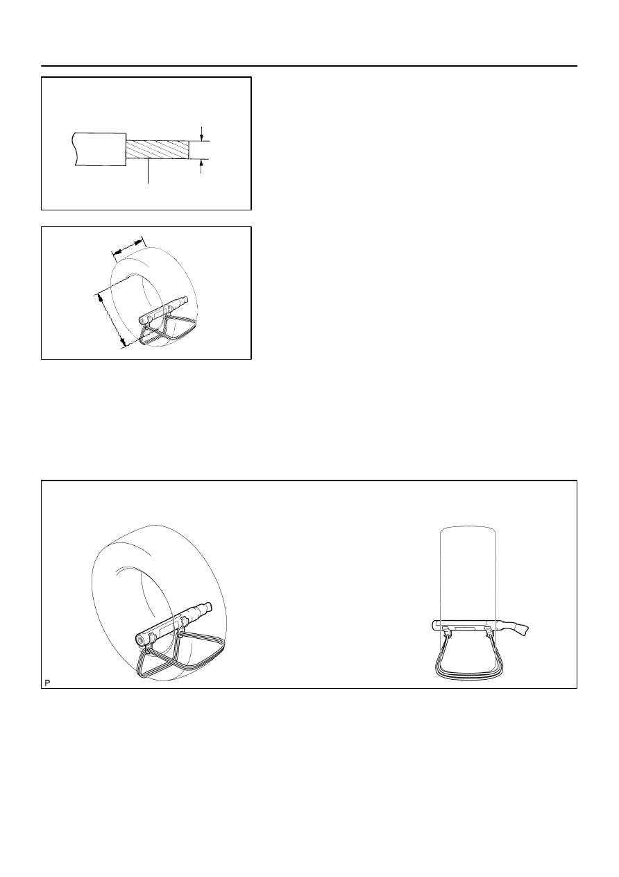
(4)
Face the upper surface of the horn button assy up-
ward. Separately tie the left and right sides of the
horn button assy to the disc wheel through the hub
nut holes. Position the horn button assy connector
so that it hangs downward through a hub hole in the
disc wheel.
CAUTION:
Make sure that the wire harness is tight. It is very dan-
gerous when looseness in the wire harness results in
the horn button assy coming free through the shock
from the airbag deploying.
Always tie down the horn button assy with the pad
side facing upward. It is very dangerous if the horn
button assy is tied down with the metal surface facing
upward as the wire harness will be cut by the shock
from the airbag deploying and the horn button assy
will be thrown into the air.
H40005
SST
Battery
H41413
SST
SST
4 Spoke Steering Wheel Assy:
3 Spoke Steering Wheel Assy:
H40176
Weight
X
Y
Y
60–22
–
SUPPLEMENTAL RESTRAINT SYSTEM
HORN BUTTON ASSY
2405
Author:
Date:
2002 CAMRY REPAIR MANUAL (RM881U)
NOTICE:
The disc wheel will be marked by the airbag deployment,
so when disposing of the airbag use a redundant disc
wheel.
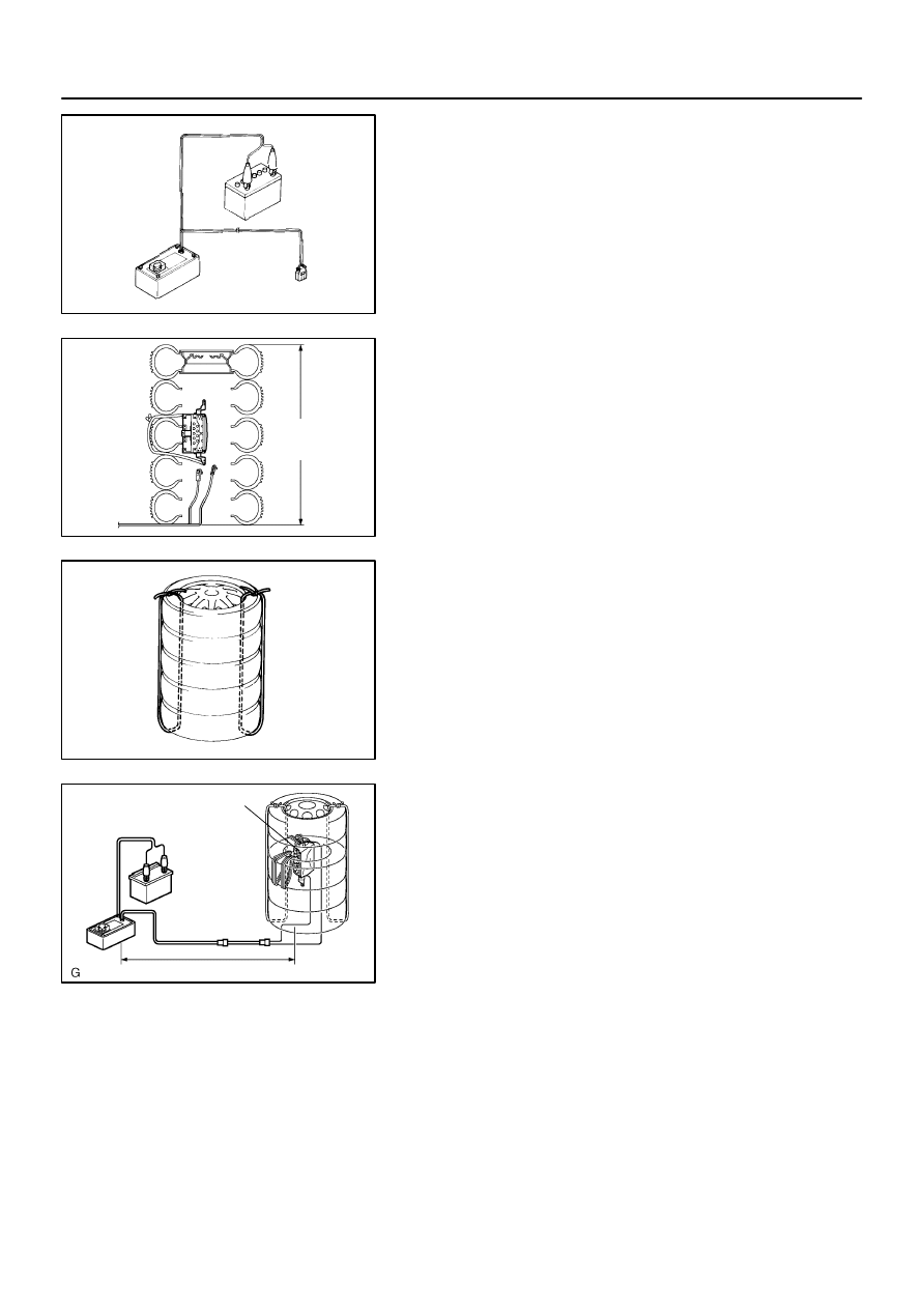
(c)
Check functioning of the SST (See step 1–(a)).
(d)
Install the SST.
CAUTION:
Place the disc wheel on the level ground.
(1)
Connect the connector of the SST.
SST
09082–00700
NOTICE:
To avoid damaging the SST connector and wire harness,
do not lock the secondary lock of the twin lock. Also, se-
cure some slack for the SST wire harness inside the disc
wheel.
(2)
Move the SST to at least 10 m (33 ft) away from the
horn button assy tied down on the disc wheel.
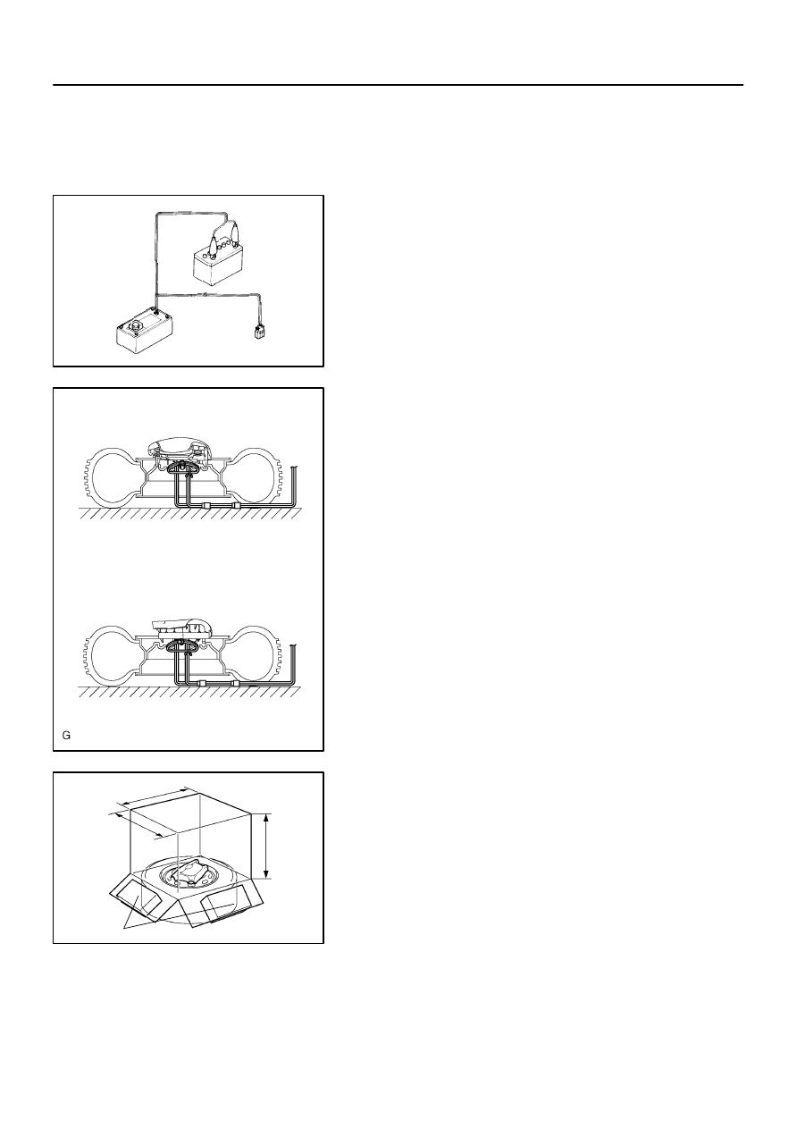
(e)
Cover the horn button assy with a cardboard box or tires.
Covering method using a cardboard box:
Cover the horn button assy with the cardboard box
and weight the cardboard box down in 4 places with
at least 190 N (20 kg, 44 lb).
Size of cardboard box:
Must exceed the following dimensions:
X = 460 mm (18.11 in.)
Y = 650 mm (25.59 in.)
NOTICE:
When dimension Y of the cardboard box exceeds the
diameter of the disc wheel with tire to which the horn
button assy is tied, X should be the following size.
X = 460 mm (18.11 in.) + width of tire
H40013
Inner Diam.
Tires
(3 or More)
Width
H40014
10 m (33 ft) or more
SST
Battery
H40177
–
SUPPLEMENTAL RESTRAINT SYSTEM
HORN BUTTON ASSY
60–23
2406
Author:
Date:
2002 CAMRY REPAIR MANUAL (RM881U)
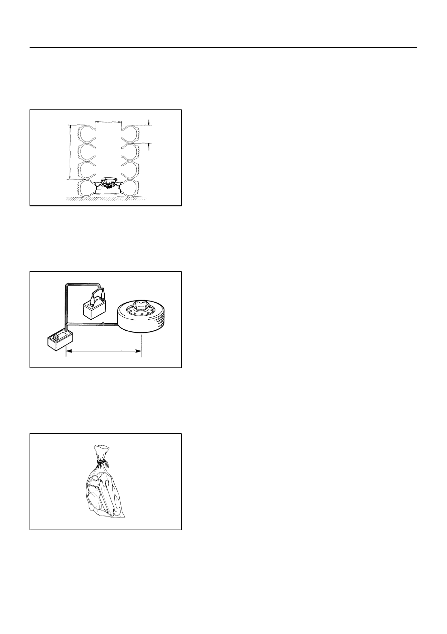
If a cardboard box smaller than the specified size is
used, the cardboard box will be broken by the shock
from the airbag deployment.
Covering method using tires:
Place at least 3 tires without disc wheel on top of the
disc wheel with tire to which the horn button assy is
tied.
Tire size: Must exceed the following dimensions–
Width: 185 mm (7.28 in.)
Inner diameter: 360 mm (14.17 in.)
CAUTION:
Do not use tires with disc wheels.
NOTICE:
The tires may be marked by the airbag deployment, so use
the redundant tires.
(f)
Deploy the airbag.
(1)
Connect the SST red clip to the battery positive (+)
terminal and the black clip to the battery negative
(–) terminal.
(2)
Check that no one is within 10 m (33 ft) area around
the disc wheel which the horn button assy is tied to.
(3)
Press the SST activation switch and deploy the air-
bag.
HINT:
The airbag deploys simultaneously as the LED of the SST ac-
tivation switch lights up.
(g)
Dispose of the horn button assy (with airbag).
CAUTION:
The horn button assy is very hot when the airbag is
deployed, so leave it alone for at least 30 minutes af-
ter deployment.
Use gloves and safety glasses when handling a horn
button assy with the deployed airbag.
Always wash your hands with water after completing
the operation.
Do not apply water, etc. to a horn button assy with the
deployed airbag.
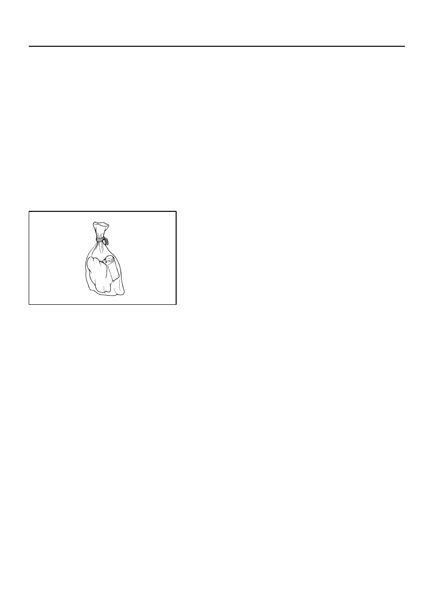
(1)
Remove the horn button assy from the disc wheel.
(2)
Place the horn button assy in a vinyl bag, tie the end
tightly and dispose of it in the same way as other
general parts disposal.

6007H–01
60–24
–
SUPPLEMENTAL RESTRAINT SYSTEM
SPIRAL CABLE SUB–ASSY
2407
Author:
Date:
2002 CAMRY REPAIR MANUAL (RM881U)
SPIRAL CABLE SUB–ASSY
COMPONENTS
(See page
60–14
)
6007I–01
H41414
–
SUPPLEMENTAL RESTRAINT SYSTEM
SPIRAL CABLE SUB–ASSY
60–25
2408
Author:
Date:
2002 CAMRY REPAIR MANUAL (RM881U)
REPLACEMENT
HINT:
COMPONENTS: See page
60–14
1.
PRECAUTION(See page
60–1
)
2.
SEPARATE BATTERY NEGATIVE TERMINAL(See page
60–1
)
3.
PLACE FRONT WHEELS FACING STRAIGHT AHEAD
4.
REMOVE STEERING WHEEL COVER LOWER NO.2
5.
REMOVE STEERING WHEEL COVER LOWER NO.2 (W/O STEERING PAD SWITCH 4 SPOKE
STEERING WHEEL)
6.
REMOVE STEERING WHEEL COVER LOWER NO.3(3 SPOKE STEERING WHEEL ASSY)
7.
REMOVE CONNECTOR COVER (W/ STEERING PAD SWITCH 4 SPOKE STEERING WHEEL)
8.
REMOVE HORN BUTTON ASSY
(See page
60–15
)
9.
REMOVE STEERING WHEEL ASSY
(See page
50–9
)
SST
09950–50013 (09951–05010, 09952–05010, 09953–05020, 09954–05021)
10.
REMOVE INSTRUMENT CLUSTER FINISH PANEL
(See page
71–12
)
11.
REMOVE STEERING COLUMN COVER
12.
REMOVE SPIRAL CABLE SUB–ASSY
(a)
Disconnect the airbag connector and connector from the
spiral cable sub–assy.
(b)
Release the 3 claws and remove the spiral cable sub–
assy.
13.
INSPECT SPIRAL CABLE SUB–ASSY
(a)
If the following condition is identified, replace the spiral cable sub–assy with new one.
Condition:
Scratches or cracks on the connector
Cracks, dents or chipping of the spiral cable sub–assy
14.
PLACE FRONT WHEELS FACING STRAIGHT AHEAD
(a)
Check that the front wheels are facing straight ahead.
H41415
H41416
Marks
60–26
–
SUPPLEMENTAL RESTRAINT SYSTEM
SPIRAL CABLE SUB–ASSY
2409
Author:
Date:
2002 CAMRY REPAIR MANUAL (RM881U)
15.
INSTALL SPIRAL CABLE SUB–ASSY
(a)
Set the turn signal switch in neutral position.
NOTICE:
Make sure of the neutral position since the pin of the turn signal switch may be snapped.
(b)
Engage the 3 claws and install the spiral cable sub–assy.
NOTICE:
When replacing the spiral cable sub–assy with new one, remove the lock pin before installing the
handle.
(c)
Connect the airbag connector and connector.
(d)
Install the steering column cover with the 2 screws.
16.
CENTER SPIRAL CABLE
(a)
Check that the ignition switch is OFF.
(b)
Check that the battery negative terminal is disconnected.
NOTICE:
Do not start the operation for 90 seconds after removing
the terminal.
(c)
Turn the cable counterclockwise by hand until it becomes
harder to turn.
(d)
Then rotate the cable clockwise about 2.5 turns to align
the marks.
HINT:
The cable will rotate about 2.5 turns to both left and right of the
center.
17.
INSTALL STEERING WHEEL ASSY
(See page
50–9
)
Torque: 50 N
⋅
m (510 kgf
⋅
cm, 37 ft
⋅
lbf)
18.
INSTALL HORN BUTTON ASSY
(See page
60–15
)
Torque: 8.8 N
⋅
m (90 kgf
⋅
cm, 78 in.
⋅
lbf)
19.
INSPECT HORN BUTTON ASSY
(See page
60–9
)
20.
INSPECT SRS WARNING LIGHT(See page
05–690
)
6007J–01
B56812
w/ Curtain Shield
Airbag:
w/ Curtain Shield
Airbag:
Steering Wheel Assy
Steering Wheel Assy
Horn Button
Assy
w/ Steering
Pad Switch:
Connector Cover
Horn Button
Assy
50 (510, 37)
Instrument Cluster Finish Panel
Steering Column
Cover
8.8 (90, 78 in.
⋅
lbf)
Headlamp Dimmer
Switch Assy
Windshield Wiper
Switch Assy
Combination
Meter Assy
Front Door
Scuff Plate LH
Front Door
Scuff Plate RH
Instrument Panel
Coin Box Sub–assy
Cowl Side Trim
Sub–assy LH
Instrument Panel
Sub–assy Upper
Air Conditioner
Control Assembly
Instrument Cluster
Finish Panel
Sub–assy Center
with Radio Receiver Assy
Instrument Panel Under
Cover Sub–assy No.1
Glove Compartment
Door Pad
Instrument Panel
Sub–assy Lower
Cowl Side Trim
Sub–assy RH
TMC made:
Console Panel
Upper Rear
RR Console Box
RR Console Box
w/ Ash Tray:
Instrument Panel
Ash Receptacle Assy
Instrument Panel
Upper Rear
Instrument
Panel Cup Holder Tray
Console Panel
Upper
Console Panel
Upper
Console Box Front
Console Box Carpet
w/o Steering
Pad Switch:
Steering Wheel
Cover Lower No.2
Steering Wheel
Cover Lower No.2
Foot Parking Brake:
Instrument Panel
Finish Panel
Lower Center
Clock Assy
Front Pillar Garnish
LH
Front Pillar Garnish LH
w/o Curtain Shield Airbag:
7.5 – 20 (76 – 204, 66 – 177 in.
⋅
lbf)
Front Pillar Garnish
RH
w/o Curtain Shield Airbag:
Front Pillar
Garnish RH
Instrument Panel Speaker
Panel Sub–assy
Instrument Panel Speaker
Panel Sub–assy No.2
Front No.2
Speaker Assy
Front No.2
Speaker Assy
N
⋅
m (kgf
⋅
cm, ft
⋅
lbf)
: Specified torque
Steering Wheel
Cover Lower No.3
3 Spoke Steering Wheel:
Combination
Meter Glass
50 (510, 37)
8.8 (90, 78 in.
⋅
lbf)
7.5 – 20 (76 – 204, 66 – 177 in.
⋅
lbf)
–
SUPPLEMENTAL RESTRAINT SYSTEM
INSTR PNL PASS L/DOOR AIR BAG ASSY
60–27
2410
Author:
Date:
2002 CAMRY REPAIR MANUAL (RM881U)
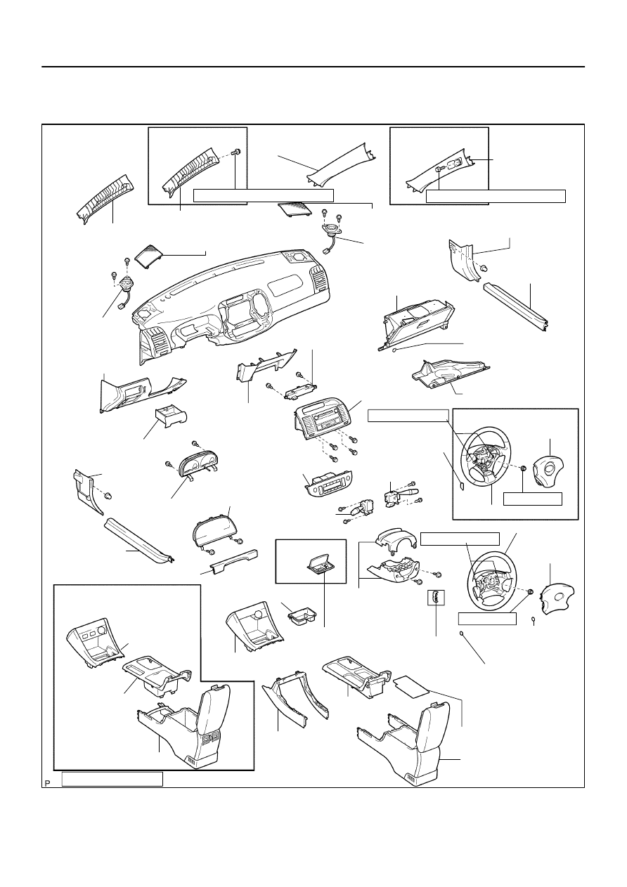
INSTR PNL PASS L/DOOR AIR BAG ASSY
COMPONENTS
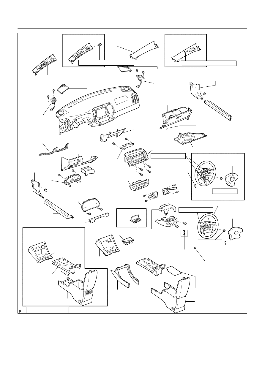
B56811
w/ Curtain Shield
Airbag:
w/ Curtain Shield
Airbag:
Steering Wheel Assy
Steering Wheel Assy
Horn Button
Assy
w/ Steering
Pad Switch:
Connector Cover
Horn Button
Assy
Instrument Cluster Finish Panel
Steering Column
Cover
Headlamp Dimmer
Switch Assy
Windshield Wiper
Switch Assy
Front Door
Scuff Plate LH
Front Door
Scuff Plate RH
Instrument Panel
Coin Box Sub–assy
Cowl Side Trim
Sub–assy LH
Instrument Panel
Sub–assy Upper
Air Conditioner
Control Assembly
Instrument Cluster
Finish Panel
Sub–assy Center
with Radio Receiver Assy
Instrument Panel Under
Cover Sub–assy No.1
Glove Compartment
Door Pad
Instrument Panel
Sub–assy Lower
Cowl Side Trim
Sub–assy RH
TMMK made:
Console Panel
Upper Rear
RR Console Box
RR Console Box
w/ Ash Tray:
Instrument Panel
Ash Receptacle Assy
Instrument Panel
Upper Rear
Instrument
Panel Cup Holder Tray
Console Panel
Upper
Console Panel
Upper
Console Box
Front
Console Box Carpet
w/o Steering
Pad Switch:
Steering Wheel
Cover Lower No.2
Steering Wheel
Cover Lower No.2
Foot Parking Brake:
Instrument Panel
Finish Panel
Lower Center
Clock Assy
Front Pillar Garnish
LH
Front Pillar Garnish LH
w/o Curtain Shield Airbag:
Front Pillar Garnish
RH
w/o Curtain Shield Airbag:
Front Pillar
Garnish RH
Instrument Panel Speaker
Panel Sub–assy
Instrument Panel Speaker
Panel Sub–assy No.2
Front No.2
Speaker Assy
Front No.2
Speaker Assy
N
⋅
m (kgf
⋅
cm, ft
⋅
lbf)
: Specified torque
Steering Wheel
Cover Lower No.3
3 Spoke Steering Wheel:
Instrument PNL
Insert Sub–assy
LWR LH
Combination
Meter Glass
50 (510, 37)
8.8 (90, 78 in.
⋅
lbf)
8.8 (90, 78 in.
⋅
lbf)
50 (510, 37)
7.5 – 20 (76 – 204, 66 in.
⋅
lbf – 15)
7.5 – 20 (76 – 204, 66 in.
⋅
lbf – 15)
Combination
Meter Assy
60–28
–
SUPPLEMENTAL RESTRAINT SYSTEM
INSTR PNL PASS L/DOOR AIR BAG ASSY
2411
Author:
Date:
2002 CAMRY REPAIR MANUAL (RM881U)
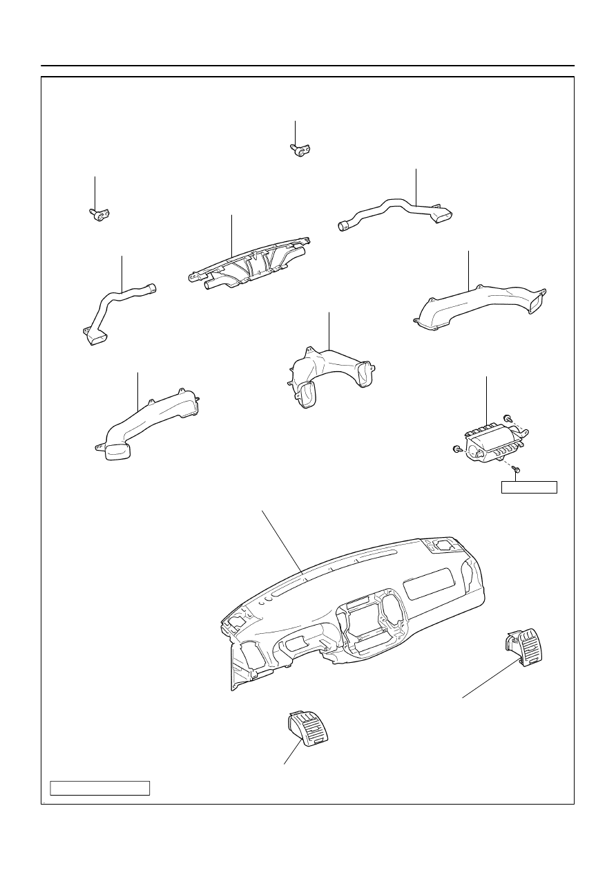
H42155
Instrument Panel Pin No.1
Instrument Panel Pin No.1
Heater to Register Duct No.2
Heater to Register Duct No.3
Heater to Register Duct No.1
Defroster Nozzle Assy
Side Defroster Nozzle Duct No.1
Side Defroster Nozzle Duct No.2
Instr Pnl Pass L/Door
Airbag Assy
20 (200, 14)
Instrument Panel Safety Pad Sub–Assy
Instrument Panel Register Assy No.1
Instrument Panel Register Assy No.2
N
⋅
m (kgf
⋅
cm, ft
⋅
lbf)
: Specified torque
–
SUPPLEMENTAL RESTRAINT SYSTEM
INSTR PNL PASS L/DOOR AIR BAG ASSY
60–29
2412
Author:
Date:
2002 CAMRY REPAIR MANUAL (RM881U)

6007K–01
60–30
–
SUPPLEMENTAL RESTRAINT SYSTEM
INSTR PNL PASS L/DOOR AIR BAG ASSY
2413
Author:
Date:
2002 CAMRY REPAIR MANUAL (RM881U)
REPLACEMENT
HINT:
COMPONENTS: See page
60–27
1.
PRECAUTION(See page
60–1
)
2.
SEPARATE BATTERY NEGATIVE TERMINAL(See page
60–1
)
3.
PLACE FRONT WHEELS FACING STRAIGHT AHEAD
4.
REMOVE STEERING WHEEL COVER LOWER NO.2
5.
REMOVE STEERING WHEEL COVER LOWER NO.2 (W/O STEERING PAD SWITCH 4 SPOKE
STEERING WHEEL)
6.
REMOVE STEERING WHEEL COVER LOWER NO.3(3 SPOKE STEERING WHEEL ASSY)
7.
REMOVE CONNECTOR COVER(W/ STEERING PAD SWITCH 4 SPOKE STEERING WHEEL)
8.
REMOVE HORN BUTTON ASSY
(See page
60–15
)
9.
REMOVE STEERING WHEEL ASSY
(See page
50–9
)
10.
REMOVE STEERING COLUMN COVER
11.
REMOVE HEADLAMP DIMMER SWITCH ASSY
(See page
50–9
)
12.
REMOVE WINDSHIELD WIPER SWITCH ASSY
(See page
50–9
)
13.
REMOVE COMBINATION METER ASSY
(See page
71–12
)
14.
REMOVE FRONT DOOR SCUFF PLATE LH
(See page
71–12
)
15.
REMOVE FRONT DOOR SCUFF PLATE RH
(See page
71–12
)
16.
REMOVE COWL SIDE TRIM SUB–ASSY LH
(See page
71–12
)
17.
REMOVE COWL SIDE TRIM SUB–ASSY RH
(See page
71–12
)
18.
REMOVE INSTRUMENT PANEL COIN BOX SUB–ASSY
(See page
71–12
)
19.
REMOVE INSTRUMENT PANEL SUB–ASSY UPPER
(See page
71–12
)
20.
REMOVE INSTRUMENT PNL INSERT SUB–ASSY LWR LH(TMMK MADE)
(See page
71–12
)
21.
REMOVE AIR CONDITIONER CONTROL ASSEMBLY(See page
71–12
)
22.
REMOVE INSTRUMENT CLUSTER FINISH PANEL SUB–ASSY CENTER
(See page
71–12
)
23.
REMOVE INSTRUMENT PANEL UNDER COVER SUB–ASSY NO.1
(See page
71–12
)

–
SUPPLEMENTAL RESTRAINT SYSTEM
INSTR PNL PASS L/DOOR AIR BAG ASSY
60–31
2414
Author:
Date:
2002 CAMRY REPAIR MANUAL (RM881U)
24.
REMOVE GLOVE COMPARTMENT DOOR PAD
(See page
71–12
)
25.
REMOVE INSTRUMENT PANEL SUB–ASSY LOWER
(See page
71–12
)
26.
SEPARATE PASSENGER AIRBAG CONNECTOR(See page
60–34
)
(a)
Disconnect the instr pnl pass l/door airbag assy connectors.
27.
REMOVE FLOOR SHIFT SHIFT LEVER KNOB SUB–ASSY(M/T TRANSAXLE)
28.
REMOVE CONSOLE PANEL UPPER REAR
(See page
71–12
)
29.
REMOVE CONSOLE BOX CARPET
(See page
71–12
)
30.
REMOVE RR CONSOLE BOX(See page
71–12
)
31.
REMOVE INSTRUMENT PANEL CUP HOLDER TRAY(W/O ASHTRAY)
(See page
71–12
)
32.
REMOVE INSTRUMENT PANEL ASH RECEPTACLE ASSY(W/ ASHTRAY)
(See page
71–12
)
33.
REMOVE CONSOLE PANEL UPPER
(See page
71–12
)
34.
REMOVE CONSOLE BOX FRONT
(See page
71–12
)
35.
REMOVE INSTRUMENT PANEL FINISH PANEL LOWER CENTER
(See page
71–12
)
36.
REMOVE FRONT PILLAR GARNISH LH(W/O CURTAIN SHIELD AIR BAG)
(See page
71–12
)
37.
REMOVE FRONT PILLAR GARNISH LH(W/ CURTAIN SHIELD AIR BAG)
(See page
71–12
)
38.
REMOVE FRONT PILLAR GARNISH RH(W/O CURTAIN SHIELD AIR BAG)
(See page
71–12
)
39.
REMOVE FRONT PILLAR GARNISH RH(W/ CURTAIN SHIELD AIR BAG)
(See page
71–12
)
40.
REMOVE INSTRUMENT PANEL SPEAKER PANEL SUB–ASSY NO.2
(See page
71–12
)
41.
REMOVE INSTRUMENT PANEL SPEAKER PANEL SUB–ASSY
(See page
71–12
)
42.
REMOVE FRONT NO.2 SPEAKER ASSY(See page
71–12
)
43.
REMOVE INSTRUMENT PANEL SAFETY PAD SUB–ASSY
(See page
71–12
)
44.
REMOVE INSTRUMENT PANEL REGISTER ASSY NO.2
(See page
71–12
)
45.
REMOVE INSTRUMENT PANEL REGISTER ASSY NO.1
(See page
71–12
)
46.
REMOVE SIDE DEFROSTER NOZZLE DUCT NO.2
(See page
71–12
)
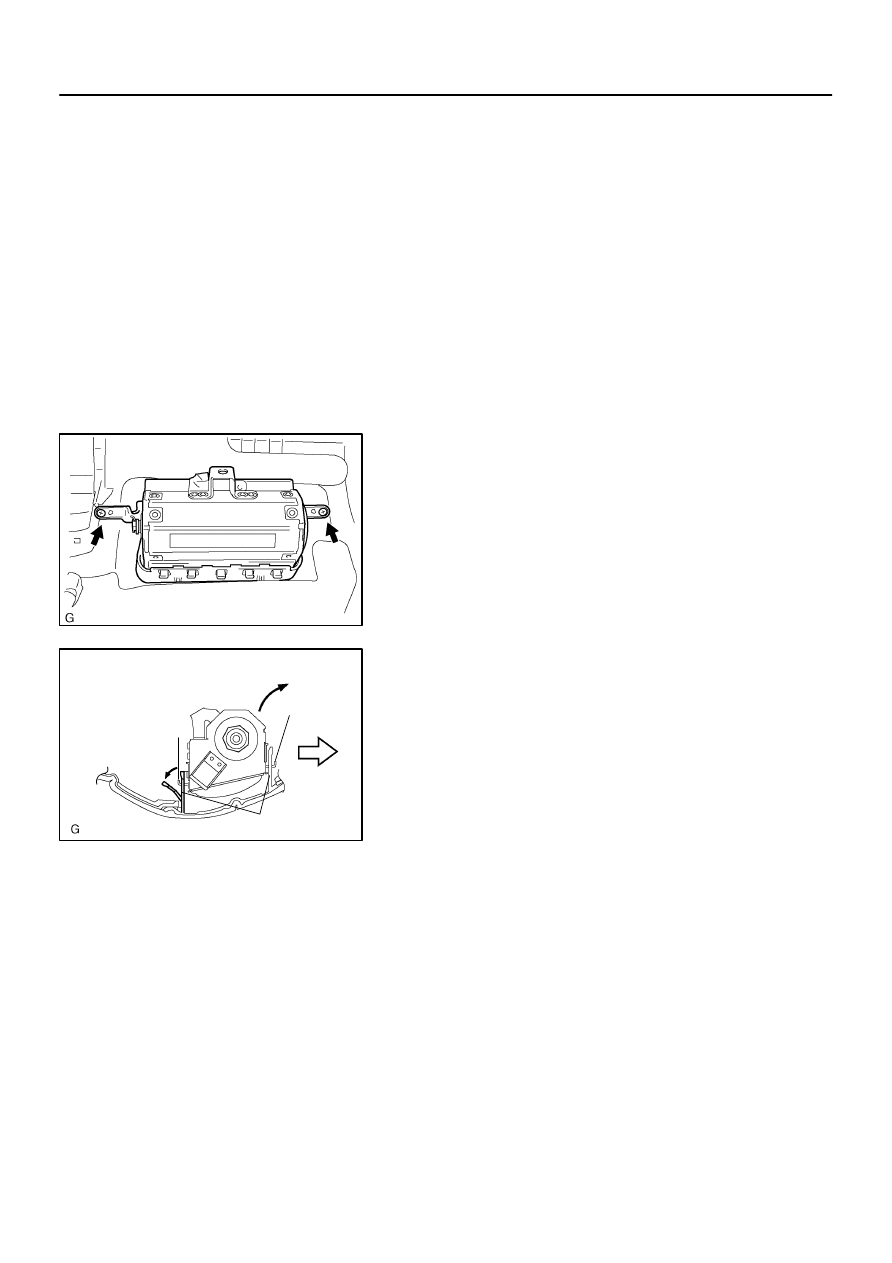
C91453
H42103
Hook
Hook
Front
Airbag Door
60–32
–
SUPPLEMENTAL RESTRAINT SYSTEM
INSTR PNL PASS L/DOOR AIR BAG ASSY
2415
Author:
Date:
2002 CAMRY REPAIR MANUAL (RM881U)
47.
REMOVE SIDE DEFROSTER NOZZLE DUCT NO.1
(See page
71–12
)
48.
REMOVE DEFROSTER NOZZLE ASSY
(See page
71–12
)
49.
REMOVE HEATER TO REGISTER DUCT NO.1
(See page
71–12
)
50.
REMOVE HEATER TO REGISTER DUCT NO.3
(See page
71–12
)
51.
REMOVE HEATER TO REGISTER DUCT NO.2
(See page
71–12
)
52.
REMOVE INSTR PNL PASS L/DOOR AIR BAG ASSY
(a)
Remove the 2 screws.
(b)
Release the rear side wall of the airbag door from the
hook by slightly deflecting it and roll the instr pnl pass l/
door airbag assy forward.
(c)
Release the front side wall of the airbag door from the oth-
er hook and remove the instr pnl pass l/door airbag assy.
53.
INSPECT INSTR PNL PASS L/DOOR AIR BAG ASSY
(See page
60–9
)
54.
INSTALL INSTR PNL PASS L/DOOR AIR BAG ASSY
55.
INSTALL FRONT PILLAR GARNISH LH(W/ CURTAIN SHIELD AIR BAG)
(See page
71–12
)
56.
INSTALL FRONT PILLAR GARNISH RH(W/ CURTAIN SHIELD AIR BAG)
(See page
71–12
)
57.
PLACE FRONT WHEELS FACING STRAIGHT AHEAD
58.
INSTALL SPIRAL CABLE SUB–ASSY
(See page
60–25
)
59.
CENTER SPIRAL CABLE(See page
60–25
)
60.
INSTALL STEERING WHEEL ASSY
(See page
50–9
)

–
SUPPLEMENTAL RESTRAINT SYSTEM
INSTR PNL PASS L/DOOR AIR BAG ASSY
60–33
2416
Author:
Date:
2002 CAMRY REPAIR MANUAL (RM881U)
61.
INSTALL HORN BUTTON ASSY
(See page
60–15
)
62.
INSPECT HORN BUTTON ASSY
(See page
60–9
)
63.
INSPECT SRS WARNING LIGHT(See page
05–690
)
6007L–01
H40004
SST
H40005
Battery
SST
60–34
–
SUPPLEMENTAL RESTRAINT SYSTEM
INSTR PNL PASS L/DOOR AIR BAG ASSY
2417
Author:
Date:
2002 CAMRY REPAIR MANUAL (RM881U)
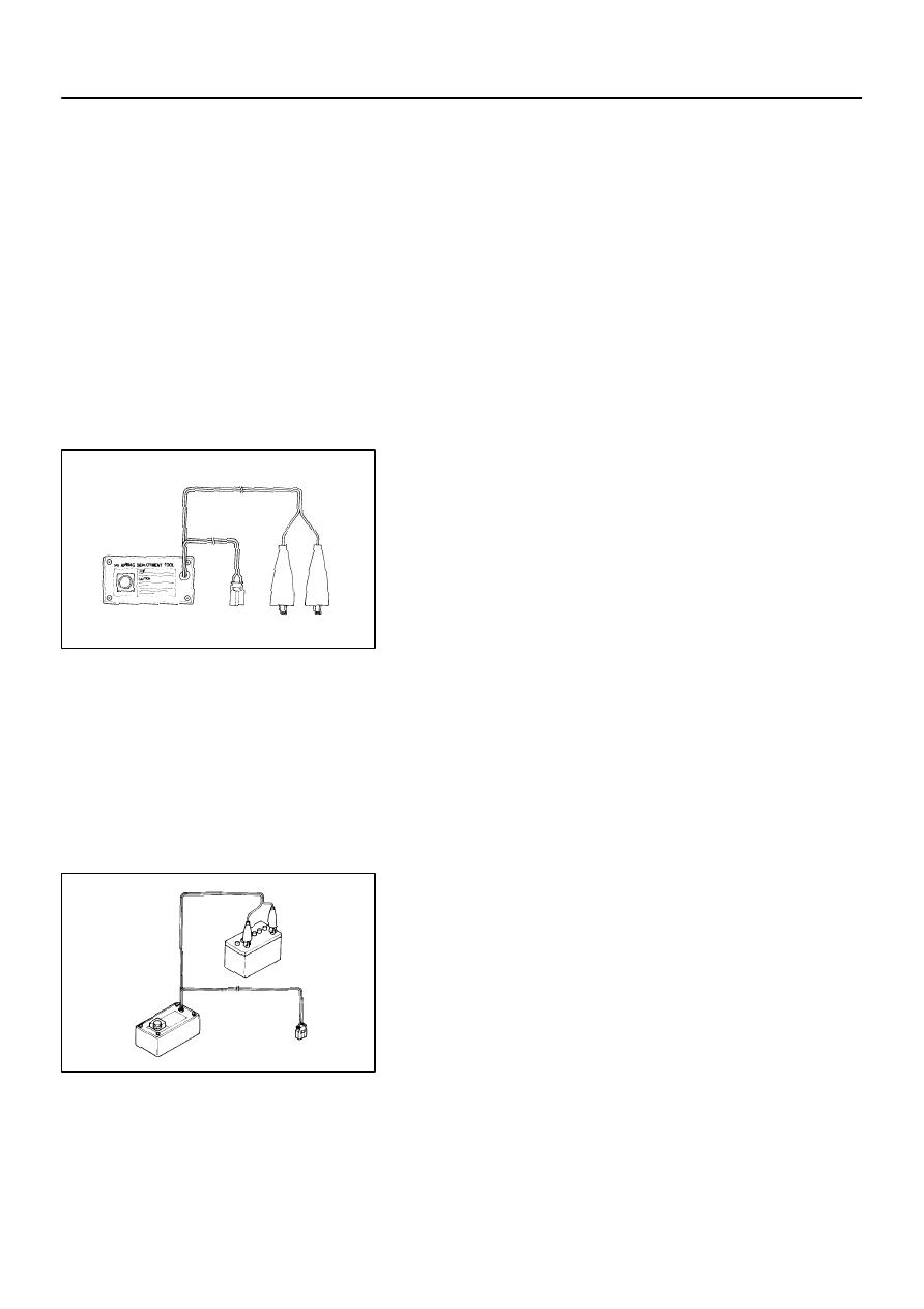
DISPOSAL
HINT:
When scrapping vehicle equipped with an SRS or disposing of a instr pnl pass l/door airbag assy, always
first deploy the airbag in accordance with the procedure described below. If any abnormality occurs with the
airbag deployment, contact the SERVICE DEPT. of TOYOTA MOTOR SALES, U.S.A., INC.
CAUTION:
Never dispose of a instr pnl pass l/door airbag assy
which has an undeployed airbag.
The airbag produces a sizeable exploding sound
when it deploys, so perform the operation out–of–
doors and where it will not create a nuisance to
nearby residents.
When deploying the airbag, always use the specified
SST (SRS Airbag Deployment Tool). Perform the op-
eration in a place away from electrical noise.
When deploying an airbag, perform the operation at
least 10 m (33 ft) away from the instr pnl pass l/door
airbag assy.
The instr pnl pass l/door airbag assy is very hot when
the airbag is deployed, so leave it alone for at least 30
minutes after deployment.
Use gloves and safety glasses when handling a instr
pnl pass l/door airbag assy with the deployed airbag.
Always wash your hands with water after completing
the operation.
Do not apply water, etc. to a instr pnl pass l/door air-
bag assy with the deployed airbag.
1.
DISPOSE INSTR PNL PASS L/DOOR AIR BAG
ASSY(WHEN SCRAPPING VEHICLE DEPLOYMENT
METHOD)
HINT:
Have a battery ready as the power source to deploy the airbag.
(a)
Check functioning of the SST (See step 1–(a) on page
60–17
).
H41430
H41695
SST
H40007
10 m (33 ft) or more
SST
Battery
–
SUPPLEMENTAL RESTRAINT SYSTEM
INSTR PNL PASS L/DOOR AIR BAG ASSY
60–35
2418
Author:
Date:
2002 CAMRY REPAIR MANUAL (RM881U)
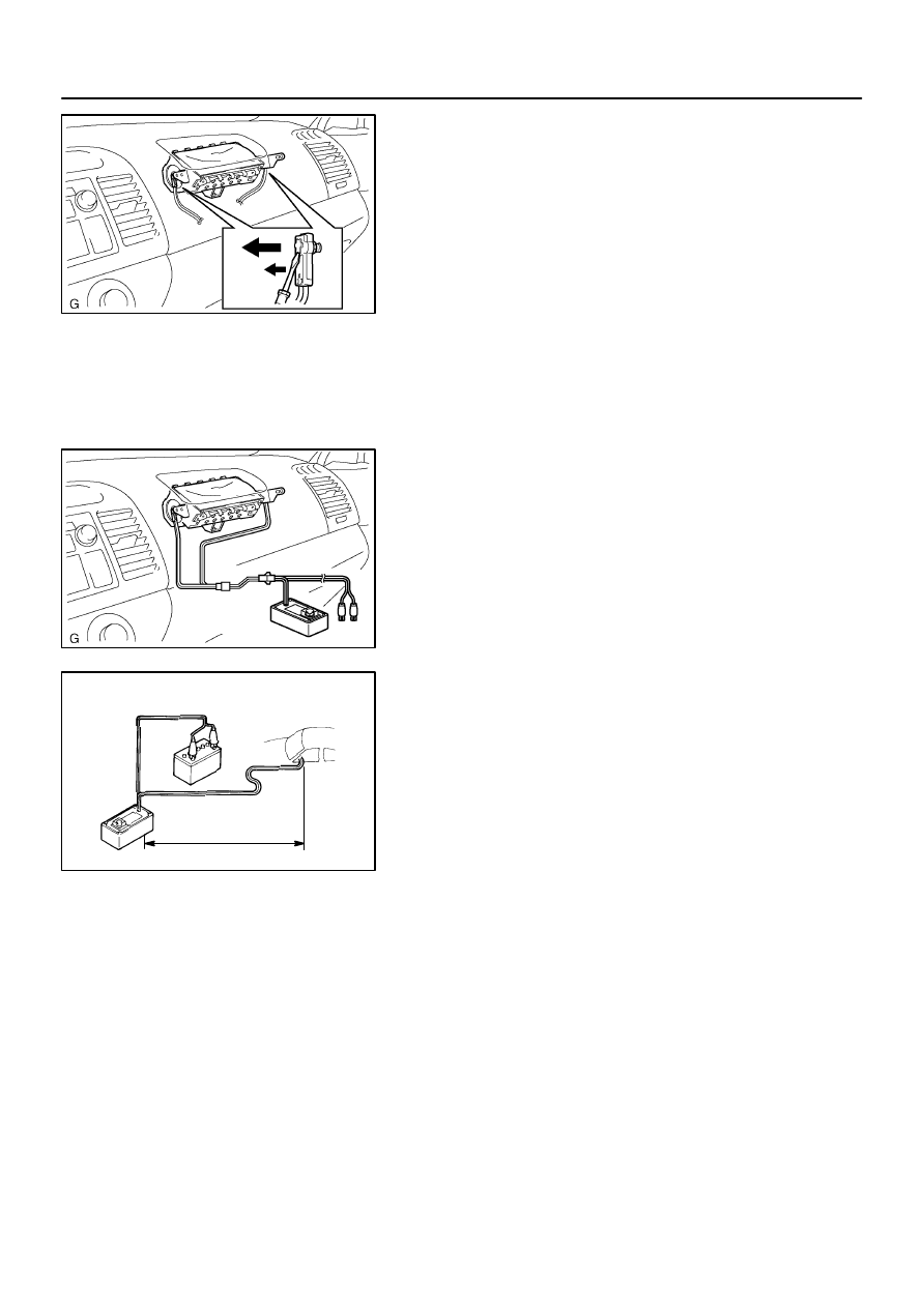
(b)
Disconnect the airbag connector.
(1)
Remove the front scuff plate.
(2)
Remove the cowl side trim sub–assy.
(3)
Remove the instrument panel under cover sub–
assy No.1.
(4)
Remove the glove compartment door pad.
(5)
Remove the instrument panel sub–assy lower.
NOTICE:
When handling the airbag connector, take care not to dam-
age the airbag wire harness.
(6)
Using a screwdriver, disconnect the airbag connec-
tors.
(c)
Install the SST.
(1)
Connect the connectors of the 3 SST to the instr pnl
pass l/door airbag assy connectors.
SST
09082–00700, 09082–00801 (09082–10801,
09082–30801)
NOTICE:
To avoid damaging the SST connector and wire harness,
do not lock the secondary lock of the twin lock.
(2)
Move the SST to at least 10 m (33 ft) away from the
front of the vehicle.
(3)
Close all the doors and windows of the vehicle.
NOTICE:
Take care not to damage the SST wire harness.
(4)
Connect the red clip of the SST to the battery posi-
tive (+) terminal and the black clip to the negative (–)
terminal.
(d)
Deploy the airbag.
(1)
Confirm that no one is inside the vehicle or within 10
m (33 ft) area around the vehicle.
(2)
Press the SST activation switch and deploy the air-
bag.
HINT:
The airbag deploys simultaneously as the LED of the SST ac-
tivation switch lights up.
(e)
Dispose of the instr pnl pass l/door airbag assy.
H41432
H40008
Wire Harness
Diameter
Stripped Wire Harness Section
60–36
–
SUPPLEMENTAL RESTRAINT SYSTEM
INSTR PNL PASS L/DOOR AIR BAG ASSY
2419
Author:
Date:
2002 CAMRY REPAIR MANUAL (RM881U)
CAUTION:
The instr pnl pass l/door airbag assy is very hot when
the airbag is deployed, so leave it alone for at least 30
minutes after deployment.
Use gloves and safety glasses when handling a instr
pnl pass l/door airbag assy with the deployed airbag.
When moving a vehicle for scrapping which has a
instr pnl pass l/door airbag assy with the deployed
airbag, use gloves and safety glasses.
Do not apply water, etc. to a instr pnl pass l/door air-
bag assy with the deployed airbag.
Always wash your hands with water after completing
the operation.
HINT:
When scrapping a vehicle, deploy the airbag and scrap the ve-
hicle with the instr pnl pass l/door airbag assy still installed.
2.
DISPOSE INSTR PNL PASS L/DOOR AIR BAG
ASSY(WHEN DISPOSING OF AIRBAG ASSEMBLY
DEPLOYMENT METHOD)
NOTICE:
When disposing of the instr pnl pass l/door airbag
assy only, never use the customer’s vehicle to deploy
the airbag.
Be sure to follow the procedure given below when de-
ploying the airbag.
HINT:
Have a battery ready as the power source to deploy the airbag.
(a)
Remove the instr pnl pass l/door airbag assy (See page
60–30
).
CAUTION:
When removing the instr pnl pass l/door airbag assy,
work must be started 90 seconds after the ignition
switch is turned to the ”LOCK” position and the nega-
tive (–) terminal cable is disconnected from the bat-
tery.
Store the instr pnl pass l/door airbag assy with the air-
bag deployment side facing upward.
(b)
Using a service–purpose wire harness for the vehicle, tie
down the instr pnl pass l/door airbag assy to the tire.
Wire harness: Stripped wire harness section
1.25 mm
2
or more (0.0019 in.
2
or more)
CAUTION:
If a wire harness which is too thin or some other thing is
used to tie down the instr pnl pass l/door airbag assy, it may
be snapped by the shock when the airbag is deployed. This
is highly dangerous. Always use a wire harness which is
at least 1.25 mm
2
(0.0019 in.
2
).
H41433
Inner
Diam.
Width
Tire
–
SUPPLEMENTAL RESTRAINT SYSTEM
INSTR PNL PASS L/DOOR AIR BAG ASSY
60–37
2420
Author:
Date:
2002 CAMRY REPAIR MANUAL (RM881U)
HINT:
To calculate the square of the stripped wire harness section:
Square = 3.14 X (Diameter)
2
divided by 4
Position the instr pnl pass l/door airbag assy inside the tire
with the airbag deployment side facing inside.
Tire size: Must exceed the following dimensions–
Width: 185 mm (7.28 in.)
Inner diameter: 360 mm (14.17 in.)
CAUTION:
Make sure that the wire harness is tight. It is very dan-
gerous if looseness in the wire harness results in the
instr pnl pass l/door airbag assy coming free due to
the shock from the airbag deploying.
Always tie down the instr pnl pass l/door airbag assy
with the airbag deployment side facing inside.
NOTICE:
The tire will be marked by the airbag deployment, so use a
redundant tire.
H40005
Battery
SST
H41434
Tires
(5 or more)
H40016
H41696
Battery
SST
Instr Pnl Pass
L/Door Airbag Assy
10 m (33 ft) or more
60–38
–
SUPPLEMENTAL RESTRAINT SYSTEM
INSTR PNL PASS L/DOOR AIR BAG ASSY
2421
Author:
Date:
2002 CAMRY REPAIR MANUAL (RM881U)
(c)
Check functioning of the SST (See step 1–(a) on page
60–17
).
(d)
Place tires.
(1)
Place at least 2 tires under the tire to which the instr
pnl pass l/door airbag assy is tied.
(2)
Place at least 2 tires over the tire to which the instr
pnl pass l/door airbag assy is tied. The top tire
should have the wheel installed.
(3)
Tie the tires together with 2 wire harness.
CAUTION:
Make sure that the wire harness is tight. It is very danger-
ous if looseness in the wire harness result in the tires com-
ing free due to the shock from the airbag deploying.
HINT:
Place the SST connector and wire harness inside tires. Secure
at least 1 m (3 ft) of slack for the wire harness.
(e)
Install the SST.
Connect the connectors of the 2 SST to the instr pnl pass
l/door airbag assy connector.
SST
09082–00700, 09082–00801 (09082–10801,
09082–30801)
NOTICE:
To avoid damaging the SST connector and wire harness,
do not lock the secondary lock of the twin lock. Also, se-
cure some slack for the SST wire harness inside the tire.
H41436
–
SUPPLEMENTAL RESTRAINT SYSTEM
INSTR PNL PASS L/DOOR AIR BAG ASSY
60–39
2422
Author:
Date:
2002 CAMRY REPAIR MANUAL (RM881U)
(f)
Deploy the airbag.
(1)
Connect the SST red clip to the battery positive (+)
terminal and the black clip to the battery negative
(–) terminal.
(2)
Check that no one is within 10 m (33 ft) area around
the tire which the instr pnl pass l/door airbag assy
is tied to.
(3)
Press the SST activation switch and deploy the air-
bag.
HINT:
The airbag deploys simultaneously as the LED of the SST ac-
tivation switch lights up.
(g)
Dispose of the instr pnl pass l/door airbag assy.
CAUTION:
The instr pnl pass l/door airbag assy is very hot when
the airbag is deployed, so leave it alone for at least 30
minutes after deployment.
Use gloves and safety glasses when handling a instr
pnl pass l/door airbag assy with the deployed airbag.
Always wash your hands with water after completing
the operation.
Do not apply water, etc. to a instr pnl pass l/door air-
bag assy with the deployed airbag.
(1)
Remove the instr pnl pass l/door airbag assy from
the tire.
(2)
Place the instr pnl pass l/door airbag assy in a vinyl
bag, tie the end tightly and dispose of it in the same
way as other general parts disposal.
6007M–01
H41535
Curtain Shield Airbag Assy LH
9.8 (100, 87 in.
⋅
lbf)
9.8 (100, 87 in.
⋅
lbf)
9.8 (100, 87 in.
⋅
lbf)
9.8 (100, 87 in.
⋅
lbf)
9.8 (100, 87 in.
⋅
lbf)
N
⋅
m (kgf
⋅
cm, ft
⋅
lbf) : Specified torque
60–40
–
SUPPLEMENTAL RESTRAINT SYSTEM
CURTAIN SHIELD AIR BAG ASSY LH
2423
Author:
Date:
2002 CAMRY REPAIR MANUAL (RM881U)
CURTAIN SHIELD AIR BAG ASSY LH
COMPONENTS

600CP–01
–
SUPPLEMENTAL RESTRAINT SYSTEM
CURTAIN SHIELD AIR BAG ASSY LH
60–41
2424
Author:
Date:
2002 CAMRY REPAIR MANUAL (RM881U)
REPLACEMENT
HINT:
COMPNENTS: See page
60–40
1.
PRECAUTION(See page
60–1
)
2.
DISCONNECT BATTERY NEGATIVE TERMINAL(See page
60–1
)
3.
REMOVE FRONT DOOR SCUFF PLATE RH
(See page
71–12
)
4.
REMOVE FRONT DOOR SCUFF PLATE LH
(See page
71–12
)
5.
REMOVE REAR DOOR SCUFF PLATE RH
(See page
61–7
)
6.
REMOVE REAR DOOR SCUFF PLATE LH
(See page
61–7
)
7.
REMOVE FRONT SEAT ASSEMBLY RH(See page
72–7
)
8.
REMOVE FRONT SEAT ASSEMBLY LH(See page
72–7
)
9.
REMOVE REAR SEAT CUSHION ASSY(See page
72–34
)
10.
REMOVE REAR SEAT BACK ASSY(See page
72–34
)
11.
REMOVE CONSOLE PANEL UPPER REAR
(See page
71–12
)
12.
REMOVE RR CONSOLE BOX(See page
71–12
)
13.
REMOVE CONSOLE PANEL UPPER
(See page
71–12
)
14.
REMOVE CONSOLE BOX FRONT(See page
72–7
)
15.
REMOVE AIR DUCT REAR NO.1
(See page
55–29
)
16.
REMOVE AIR DUCT REAR NO.2
(See page
55–29
)
17.
REMOVE CONSOLE BOX DUCT NO.1
(See page
55–29
)
18.
REMOVE FLOOR SHIFT ASSY
19.
REMOVE FRONT DOOR OPENING TRIM WEATHERSTRIP RH
(See page
76–20
)
20.
REMOVE FRONT DOOR OPENING TRIM WEATHERSTRIP LH
(See page
76–20
)
21.
REMOVE REAR DOOR OPENING TRIM WEATHERSTRIP RH
(See page
76–20
)
22.
REMOVE REAR DOOR OPENING TRIM WEATHERSTRIP LH
(See page
76–20
)
23.
REMOVE CENTER PILLAR GARNISH LOWER RH
(See page
76–20
)
24.
REMOVE CENTER PILLAR GARNISH LOWER LH
(See page
76–20
)
25.
REMOVE CENTER PILLAR GARNISH UPPER RH
(See page
76–20
)
26.
REMOVE CENTER PILLAR GARNISH UPPER LH
(See page
76–20
)
27.
REMOVE ROOF SIDE GARNISH INNER RH
(See page
76–20
)

60–42
–
SUPPLEMENTAL RESTRAINT SYSTEM
CURTAIN SHIELD AIR BAG ASSY LH
2425
Author:
Date:
2002 CAMRY REPAIR MANUAL (RM881U)
28.
REMOVE ROOF SIDE GARNISH INNER LH
(See page
76–20
)
29.
REMOVE FRONT PILLAR GARNISH RH
(See page
76–20
)
30.
REMOVE FRONT PILLAR GARNISH LH
(See page
76–20
)
31.
REMOVE ASSIST GRIP SUB–ASSY
(See page
76–20
)
32.
REMOVE RH VISOR ASSY
(See page
76–20
)
33.
REMOVE LH VISOR ASSY
(See page
76–20
)
34.
REMOVE INNER REAR VIEW MIRROR ASSY
(See page
76–20
)
35.
REMOVE ROOF CONSOLE BOX ASSY
(See page
76–20
)
36.
REMOVE ROOM LAMP ASSY NO.1
(See page
76–20
)
37.
REMOVE VISOR HOLDER
(See page
76–20
)
38.
REMOVE ROOF HEADLINING ASSY
(See page
76–20
)
C92093
H41533
–
SUPPLEMENTAL RESTRAINT SYSTEM
CURTAIN SHIELD AIR BAG ASSY LH
60–43
2426
Author:
Date:
2002 CAMRY REPAIR MANUAL (RM881U)
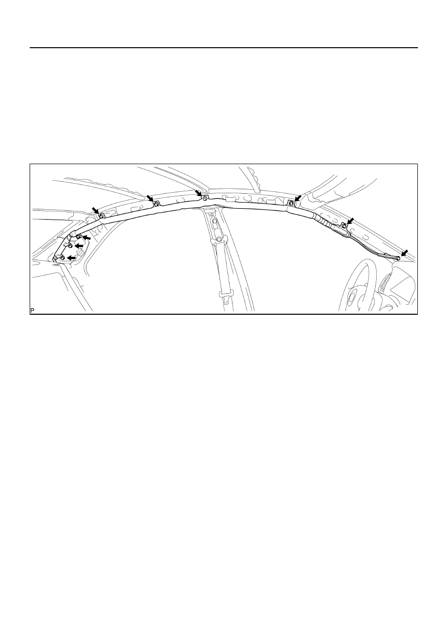
39.
REMOVE CURTAIN SHIELD AIR BAG ASSY LH
(a)
Disconnect the connector of the curtain shield airbag
assy LH.
(b)
Remove the 9 bolts and curtain shield airbag assy LH.
HINT:
Remove the bolts from front side of the vehicle in order.
40.
INSPECT CURTAIN SHIELD AIR BAG ASSY LH
(See page
60–9
)
41.
INSTALL CURTAIN SHIELD AIR BAG ASSY LH
(a)
Install the curtain shield airbag assy LH with the 9 bolts.
Torque: 9.8 N
⋅
m (100 kgf
⋅
cm, 87 in.
⋅
lbf)
HINT:
Install the bolts from rear side of the vehicle in order.
(b)
Connect the curtain shield airbag assy LH connector.
42.
INSTALL ROOF HEADLINING ASSY
(See page
76–20
)
43.
INSTALL REAR SEAT BACK ASSY(See page
72–34
)
44.
INSTALL REAR SEAT CUSHION ASSY(See page
72–34
)
45.
INSTALL FRONT SEAT ASSEMBLY LH(See page
72–7
)
46.
INSTALL FRONT SEAT ASSEMBLY RH(See page
72–7
)
47.
INSPECT SRS WARNING LIGHT(See page
05–690
)
6007O–01
H40004
SST
H40005
Battery
SST
60–44
–
SUPPLEMENTAL RESTRAINT SYSTEM
CURTAIN SHIELD AIR BAG ASSY LH
2427
Author:
Date:
2002 CAMRY REPAIR MANUAL (RM881U)
DISPOSAL
HINT:
When scrapping vehicle equipped with an SRS or disposing of a curtain shield airbag assy, always first
deploy the airbag in accordance with the procedure described below. If any abnormality occurs with the air-
bag deployment, contact the SERVICE DEPT. of TOYOTA MOTOR SALES, U.S.A., INC.
CAUTION:
Never dispose of a curtain shield airbag assy which
has an undeployed airbag.
The airbag produces a sizeable exploding sound
when it deploys, so perform the operation out–of–
doors and where it will not create a nuisance to
nearby residents.
When deploying the airbag, always use the specified
SST (SRS Airbag Deployment Tool). Perform the op-
eration in a place away from electrical noise.
When deploying an airbag, perform the operation at
least 10 m (33 ft) away from the curtain shield airbag
assy.
The curtain shield airbag assy is very hot when the
airbag is deployed, so leave it alone for at least 30
minutes after deployment.
Use gloves and safety glasses when handling a cur-
tain shield airbag assy with the deployed airbag.
Always wash your hands with water after completing
the operation.
Do not apply water, etc. to a curtain shield airbag assy
with the deployed airbag.
1.
DISPOSE CURTAIN SHIELD AIR BAG ASSY
LH(WHEN SCRAPPING VEHICLE DEPLOYMENT
METHOD)
HINT:
Have a battery ready as the power source to deploy the airbag.
(a)
Check functioning of the SST (See step 1–(a) on page
60–17
).
(b)
Disconnect the airbag connector.
(1)
Remove the rear seat cushion.
(2)
Remove the rear side seat back LH.
(3)
Remove the roof side inner garnish LH.
(4)
Disconnect the curtain shield airbag connector.
H41534
SST
H41078
10 m (33 ft) or more
SST
Battery
–
SUPPLEMENTAL RESTRAINT SYSTEM
CURTAIN SHIELD AIR BAG ASSY LH
60–45
2428
Author:
Date:
2002 CAMRY REPAIR MANUAL (RM881U)
(c)
Install the SST.
(1)
Connect the connectors of the 2 SST to the curtain
shield airbag assy LH connector.
SST
09082–00700, 09082–00801 (09082–10801,
09082–20801)
NOTICE:
To avoid damaging the SST connector and wire harness,
do not lock the secondary lock of the twin lock.
(2)
Move the SST to at least 10 m (33 ft) away from the
rear of the vehicle.
(3)
Close all the doors and windows of the vehicle.
NOTICE:
Take care not to damage the SST wire harness.
(4)
Connect the red clip of the SST to the battery posi-
tive (+) terminal and the black clip to the negative (–)
terminal.
(d)
Deploy the airbag.
(1)
Confirm that no one is inside the vehicle or within 10
m (33 ft) area around the vehicle.
(2)
Press the SST activation switch and deploy the air-
bag.
HINT:
The airbag deploys simultaneously as the LED of the SST ac-
tivation switch lights up.
(e)
Dispose of the curtain shield airbag assy LH.
CAUTION:
The curtain shield airbag assy is very hot when the
airbag is deployed, so leave it alone for at least 30
minutes after deployment.
Use gloves and safety glasses when handling a cur-
tain shield airbag assy with the deployed airbag.
When moving a vehicle for scrapping which has a
curtain shield airbag assy with the deployed airbag,
use gloves and safety glasses.
Do not apply water, etc. to a curtain shield airbag assy
with the deployed airbag.
Always wash your hands with water after completing
the operation.
HINT:
When scrapping a vehicle, deploy the airbag and scrap the ve-
hicle with the curtain shield airbag assy still installed.
H41402
H41417
60–46
–
SUPPLEMENTAL RESTRAINT SYSTEM
CURTAIN SHIELD AIR BAG ASSY LH
2429
Author:
Date:
2002 CAMRY REPAIR MANUAL (RM881U)
2.
DISPOSE CURTAIN SHIELD AIR BAG ASSY
LH(WHEN DISPOSING OF AIRBAG ASSEMBLY
DEPLOYMENT METHOD)
NOTICE:
When disposing of the curtain shield airbag assy LH
only, never use the customer’s vehicle to deploy the
airbag.
Be sure to follow the procedure given below when de-
ploying the airbag.
HINT:
Have a battery ready as the power source to deploy the airbag.
(a)
Remove the curtain shield airbag assy
(See page
60–41
).
CAUTION:
When removing the curtain shield airbag assy, work must
be started 90 seconds after the ignition switch is turned to
the ”LOCK” position and the negative (–) terminal cable is
disconnected from the battery.
(b)
Cut off the deployment section in airbag from inflator.
H40008
Wire Harness
Diameter
Stripped Wire Harness Section
H41548
Inner
Diam
Width
H41549
–
SUPPLEMENTAL RESTRAINT SYSTEM
CURTAIN SHIELD AIR BAG ASSY LH
60–47
2430
Author:
Date:
2002 CAMRY REPAIR MANUAL (RM881U)
(c)
Using a service–purpose wire harness for the vehicle, tie
down the curtain shield airbag assy to the tire.
Wire harness: Stripped wire harness section
1.25 mm
2
or more (0.0019 in.
2
or more)
CAUTION:
If the curtain shield airbag assy is tied down with too thin
wire harness, it may snap. This is highly dangerous. Al-
ways use a wire harness which is at least 1.25 mm
2
(0.0019
in.
2
).
HINT:
To calculate the square of the stripped wire harness section:
Square = 3.14 X (Diameter)
2
divided by 4
Position the curtain shield airbag assy LH inside the tire
with the airbag deployment side facing inside.
Tire size: Must exceed the following dimensions–
Width: 185 mm (7.28 in.)
Inner diameter: 360 mm (14.17 in.)
CAUTION:
Make sure that the wire harness is tight. It is very dan-
gerous if looseness in the wire harness results in the
curtain shield airbag assy LH coming free due to the
shock from the airbag deploying.
Always tie down the curtain shield airbag assy LH
with the airbag deployment side facing inside.
NOTICE:
The tire will be marked by the airbag deployment, so use a
redundant tire.
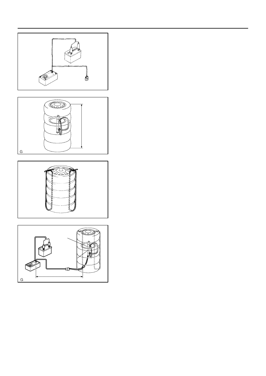
H40005
Battery
SST
H41420
Tires
(5 or more)
H40016
H41421
Battery
SST
Curtain Shield
Airbag Assy
10 m (33 ft) or more
60–48
–
SUPPLEMENTAL RESTRAINT SYSTEM
CURTAIN SHIELD AIR BAG ASSY LH
2431
Author:
Date:
2002 CAMRY REPAIR MANUAL (RM881U)
(d)
Check functioning of the SST (See step 1–(a) on page
60–17
).
(e)
Place the tires.
CAUTION:
Place the tire so that the deployment direction of the cur-
tain shield airbag assy RH will be downward.
(1)
Place at least 2 tires under the tire to which the cur-
tain shield airbag assy LH is tied.
(2)
Place at least 2 tires over the tire to which the curtain
shield airbag assy is tied. The top tire should have
the wheel installed.
(3)
Tie the tires together with 2 wire harness.
CAUTION:
Make sure that the wire harness is tight. It is very danger-
ous if looseness in the wire harness result in the tires com-
ing free due to the shock from the airbag deploying.
HINT:
Place the SST connector and wire harness inside tires. Secure
at least 1 m (3 ft) of slack for the wire harness.
(f)
Install the SST.
Connect the connectors of the 3 SST to the curtain shield
airbag assy connector.
SST
09082–00700, 09082–00801 (09082–10801,
09082–20801)
NOTICE:
To avoid damaging the SST connector and wire harness,
do not lock the secondary lock of the twin lock.
Also, secure some slack for the SST wire harness inside
the tire.
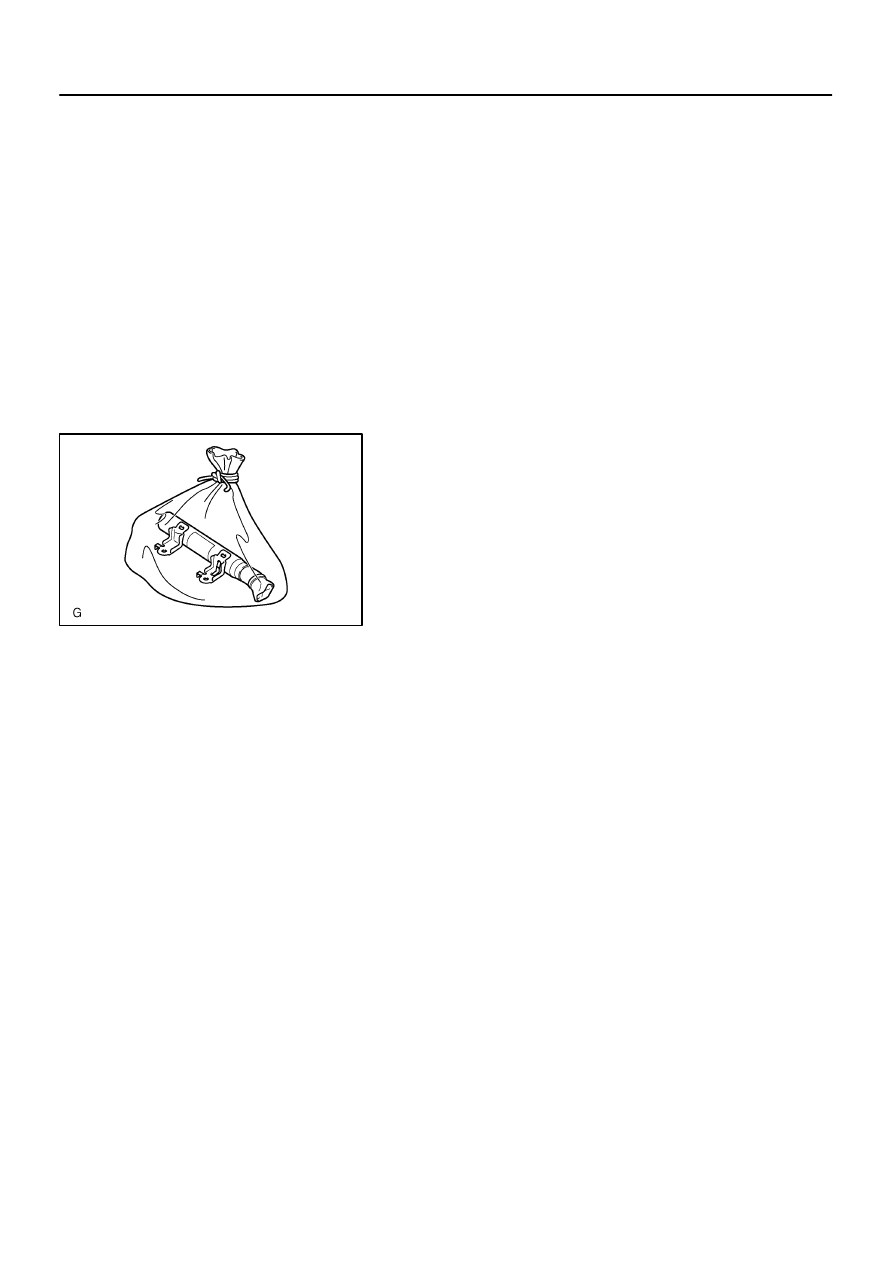
H41422
–
SUPPLEMENTAL RESTRAINT SYSTEM
CURTAIN SHIELD AIR BAG ASSY LH
60–49
2432
Author:
Date:
2002 CAMRY REPAIR MANUAL (RM881U)
(g)
Deploy the airbag.
(1)
Connect the SST red clip to the battery positive (+)
terminal and the black clip to the battery negative
(–) terminal.
(2)
Check that no one is within 10 m (33 ft) area around
the tire which the curtain shield airbag assy is tied
to.
(3)
Press the SST activation switch and deploy the air-
bag.
HINT:
The airbag deploys simultaneously as the LED of the SST ac-
tivation switch lights up.
(h)
Dispose of the curtain shield airbag assy.
CAUTION:
The curtain shield airbag assy is very hot when the
airbag is deployed, so leave it alone for at least 30
minutes after deployment.
Use gloves and safety glasses when handling a cur-
tain shield airbag assy with the deployed airbag.
Always wash your hands with water after completing
the operation.
Do not apply water, etc. to a curtain shield airbag assy
with the deployed airbag.
(1)
Remove the curtain shield airbag assy from the tire.
(2)
Place the curtain shield airbag assy in a vinyl bag,
tie the end tightly and dispose of it in the same way
as other general parts disposal.
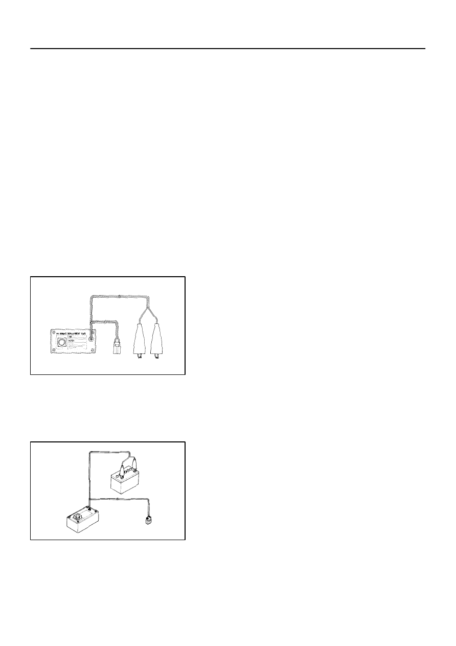
6007P–01
H40004
SST
H40005
Battery
SST
60–50
–
SUPPLEMENTAL RESTRAINT SYSTEM
FRONT SEAT AIRBAG ASSY RH
2433
Author:
Date:
2002 CAMRY REPAIR MANUAL (RM881U)
FRONT SEAT AIRBAG ASSY RH
DISPOSAL
HINT:
When scrapping vehicles equipped with an SRS or disposing of the front seat airbag assy always first deploy
the airbag in accordance with the procedure described below. If any abnormality occurs with the airbag de-
ployment, contact the SERVICE DEPT. of TOYOTA MOTOR SALES, U.S.A., INC.
When disposing of a front seat airbag assy with an airbag deployed in a collision, follow the same procedure
given in step 1–(e) in ”DISPOSAL”.
CAUTION:
Never dispose of a front seat airbag assy which has
an undeployed airbag.
The airbag produces a sizeable exploding sound
when it deploys, so perform the operation out of
doors and where it will not create a nuisance to
nearby residents.
When deploying the airbag, always use the specified
SST (SRS Airbag Deployment Tool), perform the
operation in a place away from electrical noise.
When deploying an airbag, perform the operation at
least 10 m (33 ft) away from the airbag assy.
The front seat airbag assy is very hot when the airbag
is deployed, so leave it alone for at least 30 minutes
after deployment.
Use gloves and safety glasses when handling front
seat airbag assy with the deployed airbag.
Always wash your hands with water after completing
the operation.
Do not apply water, etc. to a front seat airbag assy
with the deployed airbag.
1.
DISPOSE FRONT SEAT AIRBAG ASSY RH(WHEN
SCRAPPING VEHICLE DEPLOYMENT METHOD)
HINT:
Have a battery ready as the power source to deploy the airbag.
(a)
Check functioning of the SST (See page
60–17
).
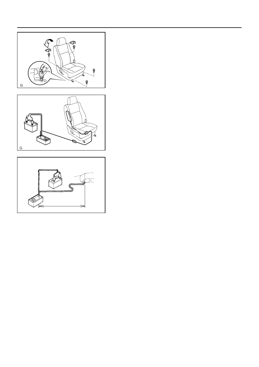
H41647
H41648
Battery
SST
H40007
10 m (33 ft) or more
–
SUPPLEMENTAL RESTRAINT SYSTEM
FRONT SEAT AIRBAG ASSY RH
60–51
2434
Author:
Date:
2002 CAMRY REPAIR MANUAL (RM881U)
(b)
Remove the front seat assy (See page
72–7
).
(c)
Disconnect the front seat airbag connector.
NOTICE:
When handling the airbag connector, take care not to
damage the airbag wire harness.
(d)
Install the SST.
(1)
Connect the connectors of the 2 SST connector to
the front seat airbag connector.
SST
09082–00700, 09082–00750
NOTICE:
To avoid damaging the SST connector and wire harness,
do not lock the secondary lock of the twin lock.
(2)
Move the SST to at least 10 m (33 ft) away from the
front of the vehicle.
(3)
Close all the doors and windows of the vehicle.
NOTICE:
Take care not to damage the SST wire harness.
(4)
Connect the red clip of the SST to the battery posi-
tive (+) terminal and the black clip of the SST to the
battery negative (–) terminal.
(e)
Deploy the airbag.
(1)
Confirm that no one is inside the vehicle or within 10
m (33 ft) area around the vehicle.
(2)
Press the activation switch of the SST and deploy
the airbag.
HINT:
The airbag deploys simultaneously as the LED of the SST ac-
tivation switch lights up.
(f)
Dispose of the front seat airbag assy.
CAUTION:
The front seat airbag assy is very hot when the airbag
is deployed, so leave it alone for at least 30 minutes
after deployment.
Use gloves and safety glasses when handling a front
seat airbag assy with the deployed airbag.
When moving a vehicle for scrapping which has a
front seat airbag assy with the deployed airbag, use
gloves and safety glasses.
Do not apply water, etc. to a front seat airbag assy
with the deployed airbag.
Always wash your hands with water after completing
the operation.
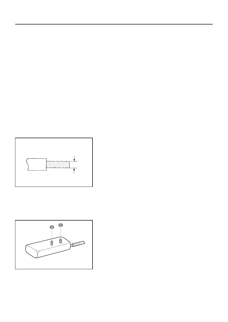
H40008
Wire Harness
Diameter
Stripped Wire Harness Section
H41437
60–52
–
SUPPLEMENTAL RESTRAINT SYSTEM
FRONT SEAT AIRBAG ASSY RH
2435
Author:
Date:
2002 CAMRY REPAIR MANUAL (RM881U)
HINT:
When scrapping a vehicle, deploy the airbag and scrap the ve-
hicle with the front seat airbag assy still installed.
2.
DISPOSE FRONT SEAT AIRBAG ASSY RH(WHEN
DISPOSING OF AIRBAG ASSEMBLY DEPLOYMENT
METHOD)
NOTICE:
When disposing of the front seat airbag assy only,
never use the customer’s vehicle to deploy the air-
bag.
Be sure to follow the procedure given below when de-
ploying the airbag.
HINT:
Have a battery ready as the power source to deploy the airbag.
(a)
Remove the front seat airbag assy.
(1)
Remove the 2 nuts and front seat airbag assy from
the seatback assembly.
CAUTION:
Store the front seat airbag assy with the airbag deployment
side facing upward.
(b)
Using a service–purpose wire harness, tie down the front
seat airbag assy.
Wire harness: Stripped wire harness section
1.25 mm
2
or more (0.0019 in
2
or more)
HINT:
To calculate the square of the stripped wire harness section :
Square = 3.14 x (Diameter)
2
divided by 4
CAUTION:
If a wire harness which is too thin or some other thing is
used to tie down the front seat airbag assy, it may be
snapped by the shock when the airbag is deployed. This is
highly dangerous. Always use a wire harness for vehicle
use which is at least 1.25 mm
2
(0.0019 in
2
).
(1)
Install the 2 nuts in the front seat airbag assy.
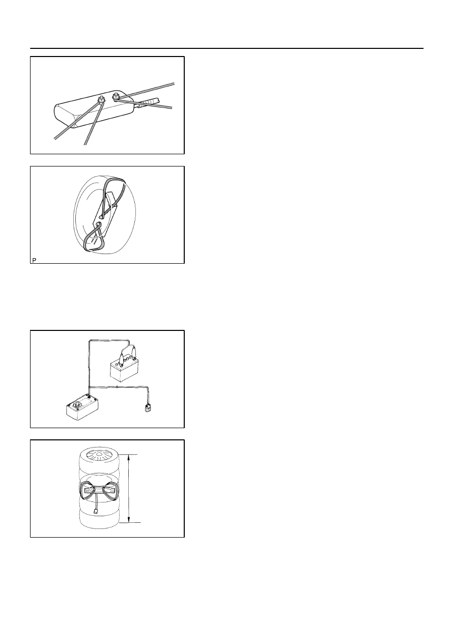
H41438
H40526
H40005
SST
Battery
H01336
Tires
(5 or More)
–
SUPPLEMENTAL RESTRAINT SYSTEM
FRONT SEAT AIRBAG ASSY RH
60–53
2436
Author:
Date:
2002 CAMRY REPAIR MANUAL (RM881U)
(2)
Wind the wire harness around the stud bolts of the
front seat airbag assy as shown in the illustration.
(3)
Position the front seat airbag assy inside the tire
with the airbag deployment direction facing inside.
Tire size : Must exceed the following dimensions:–
Width 185 mm (7.28 in.)
Inner diameter 360 mm (14.17 in.)
CAUTION:
Make sure the wire harness is tight. It is very danger-
ous if looseness in the wire harness results in the
front seat airbag assy coming free due to the shock
from the airbag deploying.
Always tie down the front seat airbag assy with the
airbag door facing inside.
NOTICE:
The tire will be marked by the airbag deployment, so use
the redundant tire.
(c)
Check functioning of the SST (See step 1–(a) on
page
60–17
).
SST
09082–00700
(d)
Place the tires.
(1)
Place at least 2 tires under the tire to which the front
seat airbag assy is tied.
(2)
Place at least 2 tires over the tire to which the front
seat airbag assy is tied. The top tire should have the
wheel installed.
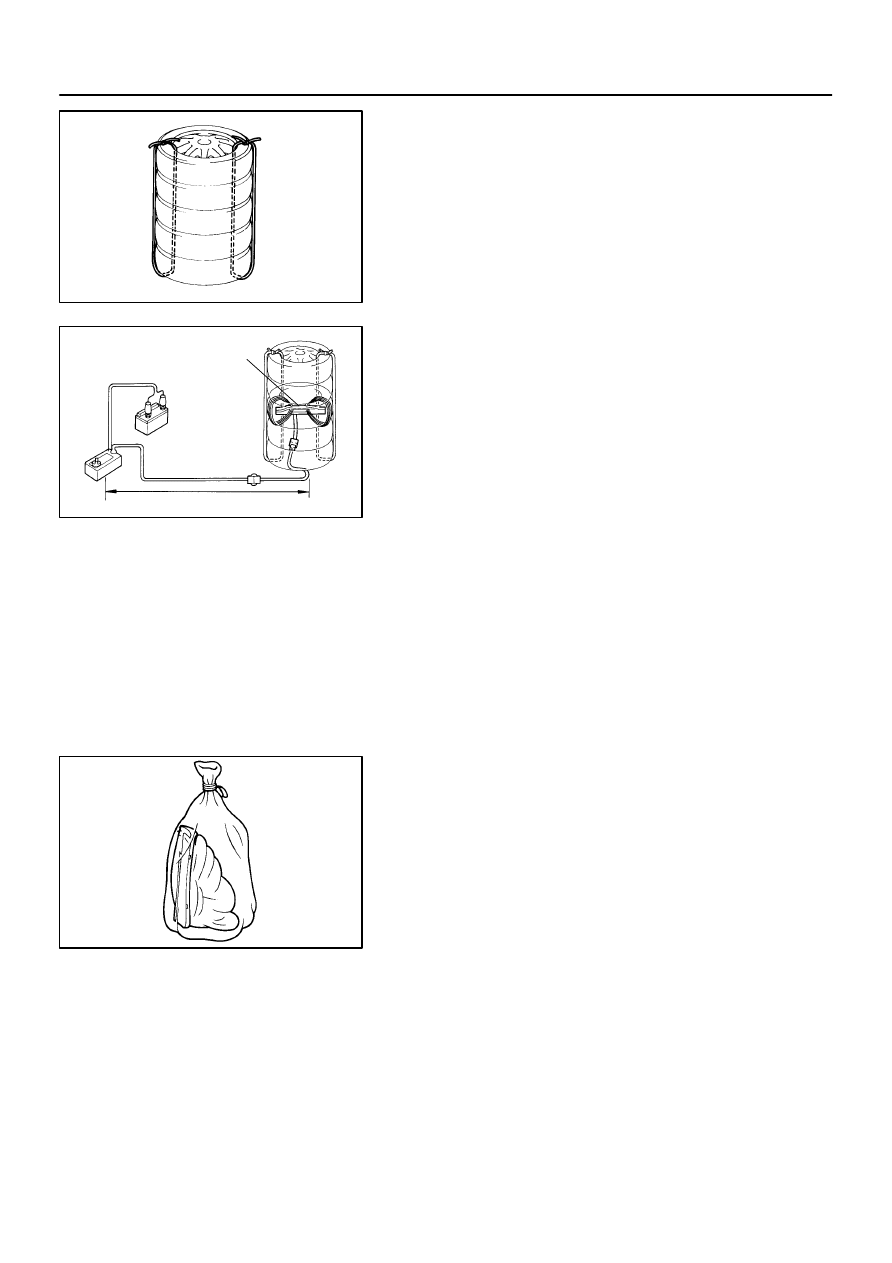
H40016
H01337
Front Seat
Airbag Assy
SST
10 m (33ft) or more
Battery
H00544
60–54
–
SUPPLEMENTAL RESTRAINT SYSTEM
FRONT SEAT AIRBAG ASSY RH
2437
Author:
Date:
2002 CAMRY REPAIR MANUAL (RM881U)
(3)
Tie the tires together with 2 wire harnesses.
CAUTION:
Make sure that the wire harness is tight. It is very danger-
ous if looseness in the wire harness results in the tires
coming free due to the shock from the airbag deploying.
HINT:
Place the SST connector and wire harness inside tires. Secure
at least 1 m (3 ft) of slack for the wire harness.
(e)
Install the SST.
Connect the connectors of the 2 SST to the front seat air-
bag assy connector.
SST
09082–00700, 09082–00750
NOTICE:
To avoid damaging the SST connector and wire harness,
do not lock the secondary lock of the twin lock. Also, se-
cure some slack for the SST wire harness inside the tire.
(f)
Deploy the airbag.
(1)
Connect the SST red clip to the battery positive (+)
terminal and the black clip to the battery negative
(–) terminal.
(2)
Check that no one is within 10 m (33 ft) area around
the tire which the front seat airbag assy is tied to.
(3)
Press the SST activation switch and deploy the air-
bag.
HINT:
The airbag deploys simultaneously as the LED of the SST ac-
tivation switch lights up.
(g)
Dispose of the front seat airbag assy.
CAUTION:
The front seat airbag assy is very hot when the airbag
is deployed, so leave it alone for at least 30 minutes
after deployment.
Use gloves and safety glasses when handling a front
seat airbag assy with the deployed airbag.
Do not apply water etc. to a front seat airbag assy with
the deployed airbag.
Always wash your hands with water after completing
the operation.
(1)
Remove the front seat airbag assy from the tire.
(2)
Place the front seat airbag assy in a vinyl bag, tie the
end tightly and dispose of it in the same way as oth-
er general parts disposal.
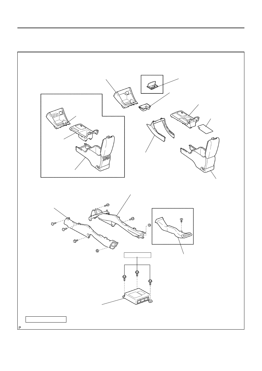
6007Q–01
H41536
w/ Ash Tray:
Foot Parking Brake:
Console Panel
Upper
Instrument Panel
Upper Rear
RR Console Box
Console Panel
Upper
Instrument Panel
Ash eceptacle Assy
Instrument Panel Cup Holder Tray
Console Box Front
Console Box
Carpet
Console Panel Upper Rear
RR Console Box
Air Duct Rear No. 1
Air Duct Rear No. 2
Console Box Duct No. 1
Auto A/C Model:
Airbag Sensor Assy Center
17.5 (178, 13)
N
⋅
m (kgf
⋅
cm, ft
⋅
lbf) : Specified torque
–
SUPPLEMENTAL RESTRAINT SYSTEM
AIR BAG SENSOR ASSY CENTER
60–55
2438
Author:
Date:
2002 CAMRY REPAIR MANUAL (RM881U)
AIR BAG SENSOR ASSY CENTER
COMPONENTS
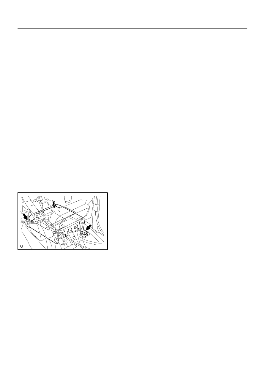
6007R–01
H42156
60–56
–
SUPPLEMENTAL RESTRAINT SYSTEM
AIR BAG SENSOR ASSY CENTER
2439
Author:
Date:
2002 CAMRY REPAIR MANUAL (RM881U)
REPLACEMENT
HINT:
COMPONENTS: See page
60–55
1.
PRECAUTION(See page
60–1
)
2.
DISCONNECT BATTERY NEGATIVE TERMINAL(See page
60–1
)
3.
REMOVE CONSOLE PANEL UPPER REAR
(See page
71–12
)
4.
REMOVE CONSOLE BOX CARPET
(See page
71–12
)
5.
REMOVE RR CONSOLE BOX(See page
71–12
)
6.
REMOVE INSTRUMENT PANEL CUP HOLDER TRAY(W/O ASHTRAY)
(See page
71–12
)
7.
REMOVE INSTRUMENT PANEL ASH RECEPTACLE ASSY(W/ ASHTRAY)
(See page
71–12
)
8.
REMOVE CONSOLE PANEL UPPER
(See page
71–12
)
9.
REMOVE CONSOLE BOX FRONT
(See page
71–12
)
10.
REMOVE AIR DUCT REAR NO.1
(See page
55–29
)
11.
REMOVE AIR DUCT REAR NO.2
(See page
55–29
)
12.
REMOVE CONSOLE BOX DUCT NO.1(AUTO AIR CONDITIONER)
(See page
55–29
)
13.
REMOVE AIR BAG SENSOR ASSY CENTER
(a)
Disconnect the 3 connectors from the airbag sensor assy
center.
(b)
Remove the 3 bolts and air bag sensor assy center.
14.
INSPECT AIR BAG SENSOR ASSY CENTER
(See page
60–9
)
15.
INSTALL AIR BAG SENSOR ASSY CENTER
(a)
Check that the ignition switch turn OFF.
(b)
Check that the battery negative terminal is disconnected.
NOTICE:
Do not start the operation for 90 seconds after removing the terminal.
(c)
Temporarily install the air bag sensor assy center with the 3 bolts.
(d)
Tighten the 3 bolts to the specified torque.
Torque: 17.5 N
⋅
m (178 kgf
⋅
cm, 13 ft
⋅
lbf)
(e)
Connect the connector to the air bag sensor assy center.
(f)
Check that no play is identified.
(g)
Check that the water–proof sheet is properly set.
16.
INSPECT SRS WARNING LIGHT(See page
05–690
)
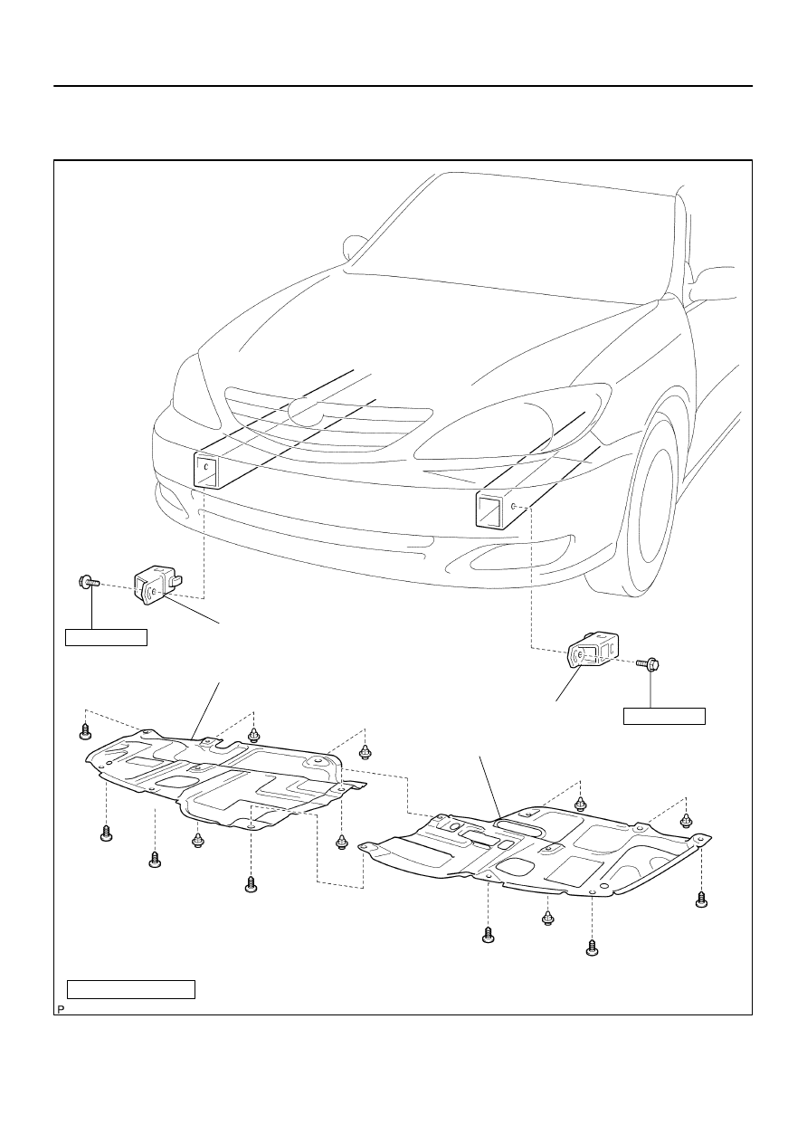
6007S–01
H41544
Airbag Front RH Sensor
Airbag Sensor Front LH
17.5 (178, 13)
17.5 (178, 13)
N
⋅
m (kgf
⋅
cm, ft
⋅
lbf) : Specified torque
Engine Under Cover RH
Engine Under Cover LH
–
SUPPLEMENTAL RESTRAINT SYSTEM
AIR BAG FRONT RH SENSOR
60–57
2440
Author:
Date:
2002 CAMRY REPAIR MANUAL (RM881U)
AIR BAG FRONT RH SENSOR
COMPONENTS
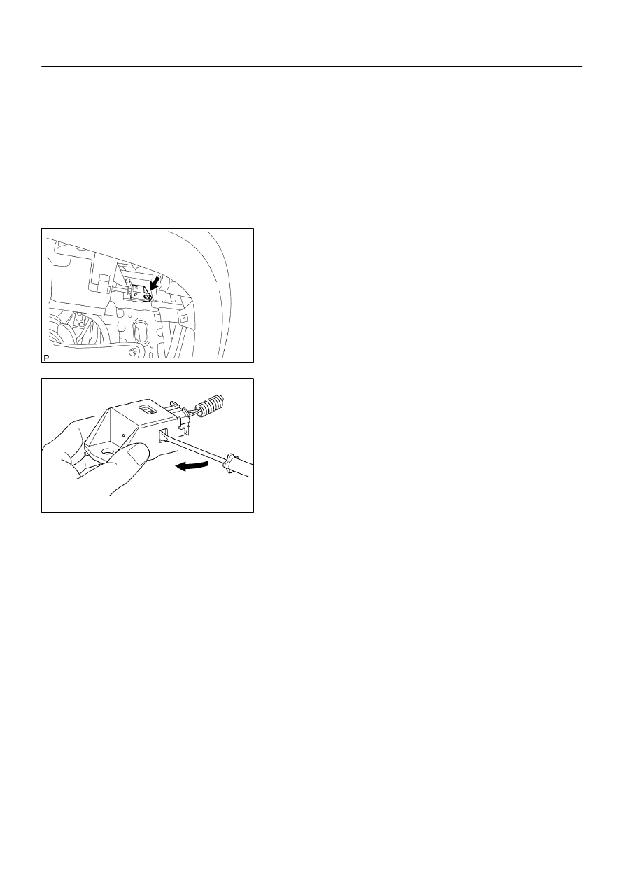
6007T–01
C93765
C84229
60–58
–
SUPPLEMENTAL RESTRAINT SYSTEM
AIR BAG FRONT RH SENSOR
2441
Author:
Date:
2002 CAMRY REPAIR MANUAL (RM881U)
REPLACEMENT
HINT:
COMPONENTS: See page
60–57
1.
PRECAUTION(See page
60–1
)
2.
DISCONNECT BATTERY NEGATIVE TERMINAL(See page
60–1
)
3.
REMOVE ENGINE UNDER COVER RH
4.
REMOVE AIR BAG FRONT RH SENSOR
(a)
Remove the bolt and front airbag sensor RH.
(b)
Disconnect the connector from the front airbag sensor
RH.
HINT:
Insert a screw driver in any of the three opening sections of the
sensor and slide the sensor to disconnect it from the connector.
5.
INSPECT AIR BAG FRONT RH SENSOR
(See page
60–9
)
6.
INSTALL AIR BAG FRONT RH SENSOR
(a)
Check that the ignition switch trun OFF.
(b)
Check that the battery negative (–) terminal is disconnected.
NOTICE:
Do not start the operation for 90 seconds after removing the terminal.
(c)
Install the front airbag sensor RH with the bolt.
Torque: 17.5 N
⋅
m (178 kgf
⋅
cm, 13 ft
⋅
lbf)
(d)
Connect the connector to the front airbag sensor RH.
(e)
Check that no play is identified.
7.
INSPECT SRS WARNING LIGHT(See page
05–690
)

6007U–01
–
SUPPLEMENTAL RESTRAINT SYSTEM
AIR BAG SENSOR FRONT LH
60–59
2442
Author:
Date:
2002 CAMRY REPAIR MANUAL (RM881U)
AIR BAG SENSOR FRONT LH
COMPONENTS
(See page
60–57
)
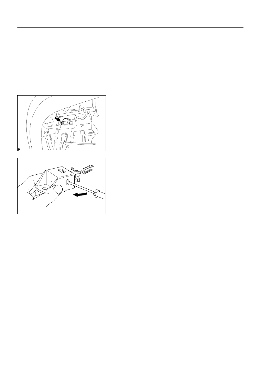
6007V–01
C93764
C84229
60–60
–
SUPPLEMENTAL RESTRAINT SYSTEM
AIR BAG SENSOR FRONT LH
2443
Author:
Date:
2002 CAMRY REPAIR MANUAL (RM881U)
REPLACEMENT
HINT:
COMPONENTS: See page
60–57
1.
PRECAUTION(See page
60–1
)
2.
DISCONNECT BATTERY NEGATIVE TERMINAL(See page
60–1
)
3.
REMOVE ENGINE UNDER COVER LH
4.
REMOVE AIR BAG SENSOR FRONT LH
(a)
Remove the bolt and front airbag sensor LH.
(b)
Disconnect the connector from the front airbag sensor
LH.
HINT:
Insert a screw driver in any of the three opening sections of the
sensor and slide the sensor to disconnect it from the connector.
5.
INSPECT AIR BAG SENSOR FRONT LH
(See page
60–9
)
6.
INSTALL AIR BAG SENSOR FRONT LH
(a)
Check that the ignition switch is OFF.
(b)
Check that the battery negative (–) terminal is disconnected.
NOTICE:
Do not start the operation for 90 seconds after removing the terminal.
(c)
Install the front airbag sensor LH with the bolt.
Torque: 17.5 N
⋅
m (178 kgf
⋅
cm, 13 ft
⋅
lbf)
(d)
Connect the connector to the front airbag sensor LH.
(e)
Check that no play is identified.
7.
INSPECT SRS WARNING LIGHT(See page
05–690
)
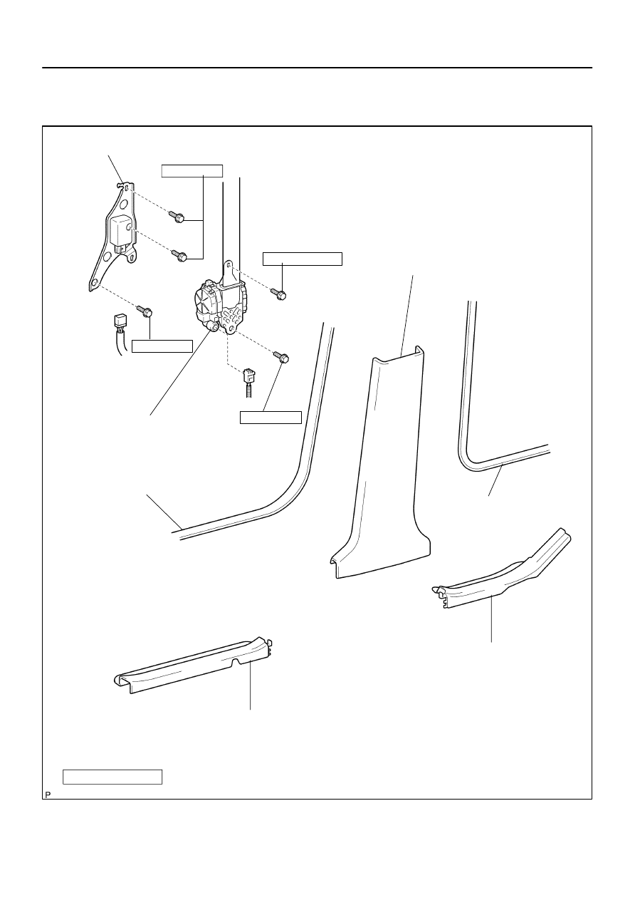
6007W–01
H41545
Rear Door Scuff Plate RH
Front Door Scuff Plate RH
Front Door Opening Trim
Weatherstrip RH
Center Pillar Garnish Lower RH
Rear Door Opening Trim
Weatherstrip RH
Front Seat Outer Belt Assy RH
Side Airbag Sensor Assy RH
20 (204, 15)
20 (204, 15)
8.5 (87, 75 in.
⋅
lbf)
42 (420, 31)
N
⋅
m (kgf
⋅
cm, ft
⋅
lbf) : Specified torque
–
SUPPLEMENTAL RESTRAINT SYSTEM
SIDE AIR BAG SENSOR ASSY RH
60–61
2444
Author:
Date:
2002 CAMRY REPAIR MANUAL (RM881U)
SIDE AIR BAG SENSOR ASSY RH
COMPONENTS
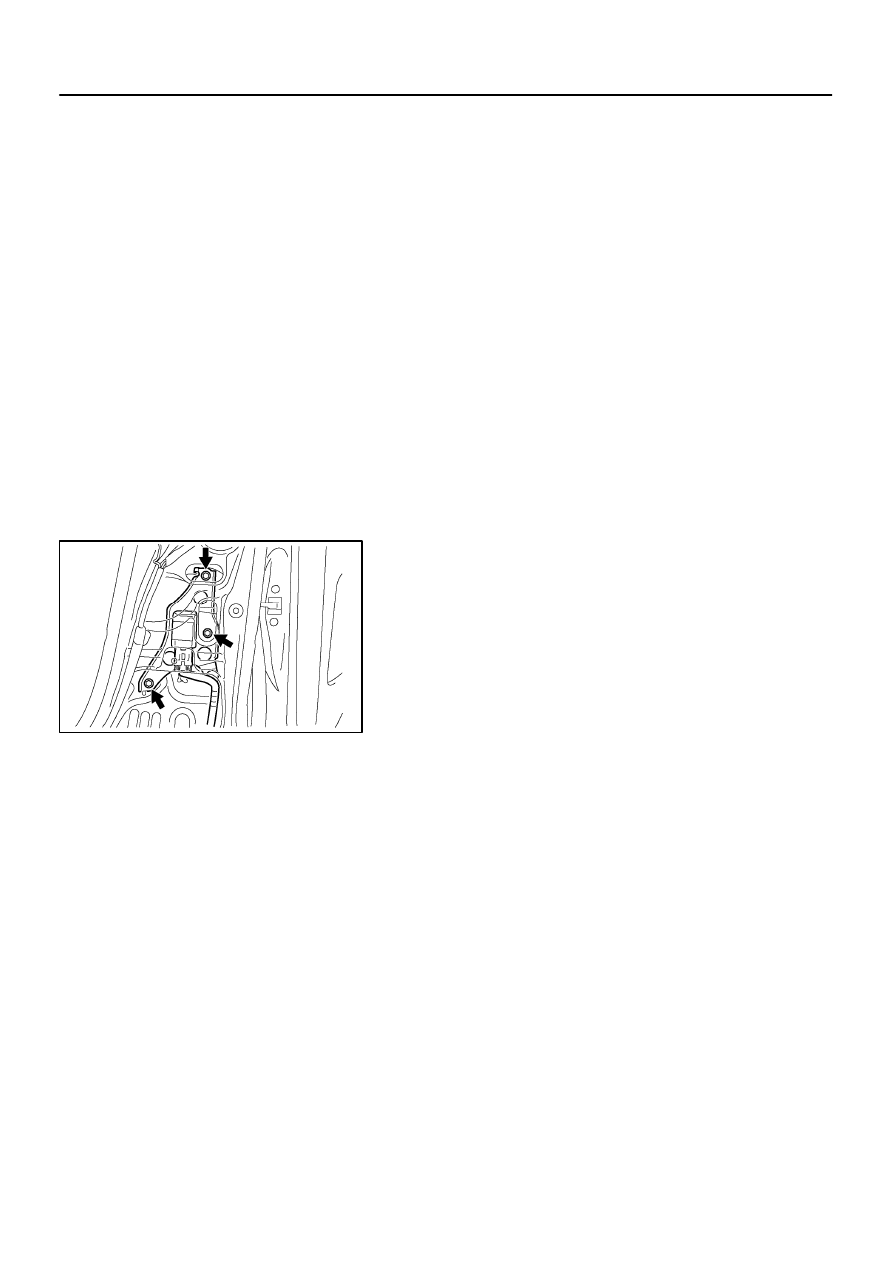
6007X–01
H41550
60–62
–
SUPPLEMENTAL RESTRAINT SYSTEM
SIDE AIR BAG SENSOR ASSY RH
2445
Author:
Date:
2002 CAMRY REPAIR MANUAL (RM881U)
REPLACEMENT
HINT:
COMPONENTS: See page
60–61
1.
PRECAUTION(See page
60–1
)
2.
DISCONNECT BATTERY NEGATIVE TERMINAL(See page
60–1
)
3.
REMOVE FRONT DOOR SCUFF PLATE RH
(See page
71–12
)
4.
REMOVE REAR DOOR SCUFF PLATE RH
(See page
71–12
)
5.
REMOVE FRONT DOOR OPENING TRIM WEATHERSTRIP RH
(See page
61–7
)
6.
REMOVE REAR DOOR OPENING TRIM WEATHERSTRIP RH
(See page
61–7
)
7.
REMOVE CENTER PILLAR GARNISH LOWER RH
(See page
61–7
)
8.
REMOVE FRONT SEAT OUTER BELT ASSY RH
(See page
61–7
)
9.
REMOVE SIDE AIR BAG SENSOR ASSY RH
(a)
Disconnect the connector from the side airbag sensor
assy RH.
(b)
Remove the 3 bolts and side airbag sensor assy RH.
10.
INSPECT SIDE AIR BAG SENSOR ASSY RH
(See page
60–9
)
11.
INSTALL SIDE AIR BAG SENSOR ASSY RH
(a)
Install the 3 bolts and side airbag sensor assy RH.
Torque: 20 N
⋅
m (204 kgf
⋅
cm, 15 ft
⋅
lbf)
(b)
Connect the side airbag sensor connector.
NOTICE:
Installation of the connector is done with the sensor assembly installed. Make sure the sensor
assembly is installed with the specified torque.
If the sensor assembly has been dropped, or there are cracks, dents or other defects in the
case, bracket or connector, replace the sensor assembly with a new one.
When installing the sensor assembly, take care that the SRS wiring does not interfere with other
parts and is not pinched between other parts.
After installation, shake the sensor assembly to check that there is no looseness.

–
SUPPLEMENTAL RESTRAINT SYSTEM
SIDE AIR BAG SENSOR ASSY RH
60–63
2446
Author:
Date:
2002 CAMRY REPAIR MANUAL (RM881U)
12.
INSTALL FRONT SEAT OUTER BELT ASSY RH
Torque:
Upper bolt: 8.5 N
⋅
m (87 kgf
⋅
cm, 75 in.
⋅
lbf)
Lower bolt: 42 N
⋅
m (420 kgf
⋅
cm, 31 ft
⋅
lbf)
13.
INSPECT SRS WARNING LIGHT(See page
05–690
)
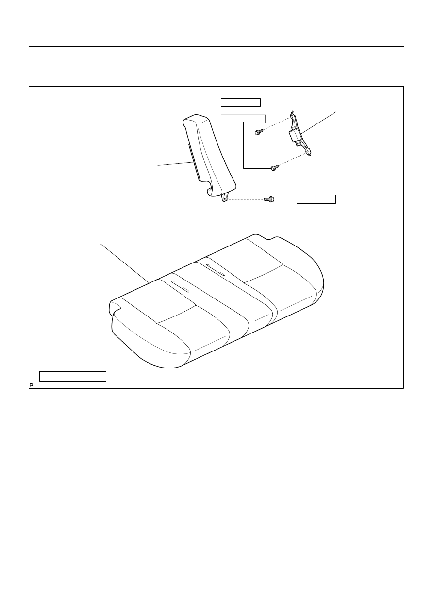
6007Y–01
H41546
Rear Seat Cushion Assy
Rear Side Seat Back Assy LH
Airbag Sensor Rear LH
17.5 (178, 13)
N
⋅
m (kgf
⋅
cm, ft
⋅
lbf)
: Specified torque
18 (184, 13)
Property Class 8T
Property Class 6T
20 (200, 14)
60–64
–
SUPPLEMENTAL RESTRAINT SYSTEM
AIR BAG SENSOR REAR LH
2447
Author:
Date:
2002 CAMRY REPAIR MANUAL (RM881U)
AIR BAG SENSOR REAR LH
COMPONENTS
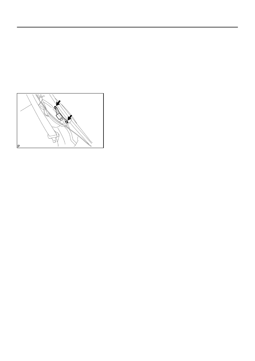
6007Z–01
C92096
–
SUPPLEMENTAL RESTRAINT SYSTEM
AIR BAG SENSOR REAR LH
60–65
2448
Author:
Date:
2002 CAMRY REPAIR MANUAL (RM881U)
REPLACEMENT
HINT:
COMPNENTS: See page
60–64
1.
PRECAUTION(See page
60–1
)
2.
DISCONNECT BATTERY NEGATIVE TERMINAL(See page
60–1
)
3.
REMOVE CUSHION ASSY, RR SEAT(See page
72–34
)
4.
REMOVE REAR SIDE SEAT BACK ASSY LH
(See page
72–34
)
5.
REMOVE AIR BAG SENSOR REAR LH
(a)
Disconnect the connector of the airbag sensor rear LH.
(b)
Remove the 2 bolts and the airbag sensor rear LH.
6.
INSTALL AIR BAG SENSOR REAR LH
(a)
Select a suitable bolt (See page
60–1
).
(b)
Install the airbag sensor rear LH with the 2 bolts.
Torque:
Property class 6T: 17.5 N
⋅
m (178 kgf
⋅
cm, 13 ft
⋅
lbf)
Property class 8T: 20 N
⋅
m (200 kgf
⋅
cm, 14 ft
⋅
lbf)
(c)
Connect the connector of the airbag sensor rear LH.
NOTICE:
Installation of the connector is done with the sensor assembly installed. Make sure the sensor
assembly is installed with the specified torque.
If the sensor assembly has been dropped, or there are cracks, dents or other defects in the
case, bracket or connector, replace the sensor assembly with a new one.
When installing the sensor assembly, take care that the SRS wiring does not interfere with other
parts and is not pinched between other parts.
After installation, shake the sensor assembly to check that there is no looseness.
7.
INSPECT AIR BAG SENSOR REAR LH
(See page
60–9
)
8.
INSTALL REAR SIDE SEAT BACK ASSY LH
(See page
72–34
)
9.
INSPECT SRS WARNING LIGHT(See page
05–690
)
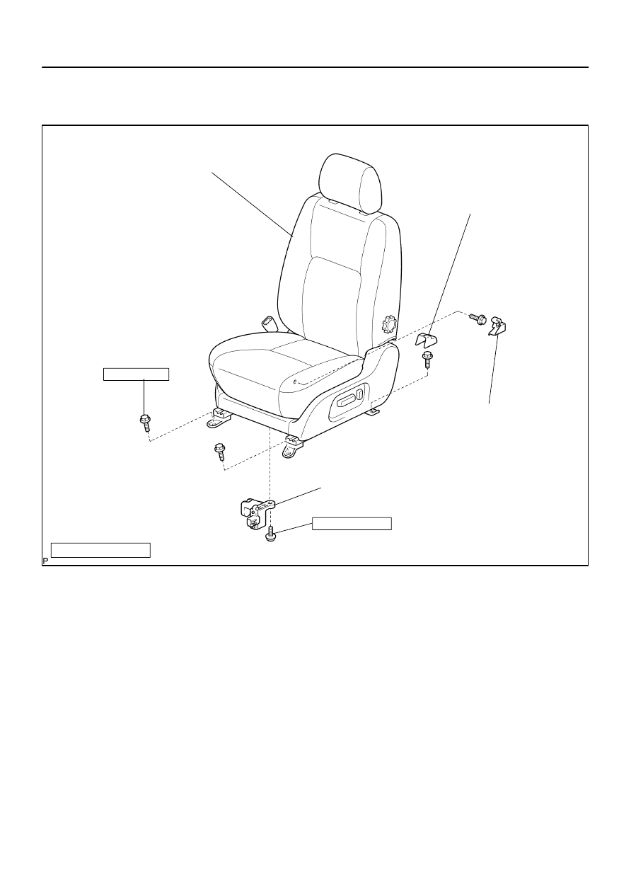
60080–01
H41547
Front Seat Assy LH
Seat Position Airbag Sensor
8.0 (82, 71 in.
⋅
lbf)
36.8 (375, 27)
Front Seat Track Cover RH Rear Inner
N
⋅
m (kgf
⋅
cm, ft
⋅
lbf) : Specified torque
Front Seat Track Cover LH Rear Inner
Power Seat:
Manual Seat:
Seat Track Cover Upper Rear
Seat Track Upper Rail Cover RH
Power Seat:
Manual Seat:
60–66
–
SUPPLEMENTAL RESTRAINT SYSTEM
SEAT POSITION AIR BAG SENSOR
2449
Author:
Date:
2002 CAMRY REPAIR MANUAL (RM881U)
SEAT POSITION AIR BAG SENSOR
COMPONENTS
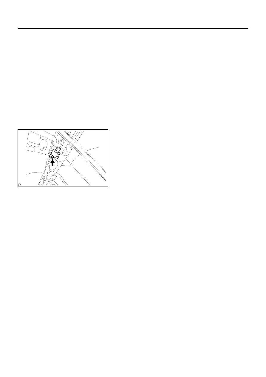
60081–01
H41697
–
SUPPLEMENTAL RESTRAINT SYSTEM
SEAT POSITION AIR BAG SENSOR
60–67
2450
Author:
Date:
2002 CAMRY REPAIR MANUAL (RM881U)
REPLACEMENT
HINT:
COMPNENTS: See page
60–66
1.
PRECAUTION(See page
60–1
)
2.
DISCONNECT BATTERY NEGATIVE TERMINAL(See page
60–1
)
3.
REMOVE FRONT SEAT TRACK COVER RH REAR INNER(POWER SEAT)
4.
REMOVE FRONT SEAT TRACK COVER LH REAR INNER(POWER SEAT)
5.
REMOVE SEAT TRACK COVER UPPER REAR(MANUAL SEAT)
6.
REMOVE SEAT TRACK UPPER RAIL COVER RH(MANUAL SEAT)
7.
REMOVE FRONT SEAT ASSY LH(See page
72–7
)
8.
REMOVE SEAT POSITION AIR BAG SENSOR
(a)
Disconnect the connector of the seat position sensor.
(b)
Using a torx socket wrench (T30), remove the torx screw
and seat position sensor.
9.
INSTALL SEAT POSITION AIR BAG SENSOR
(a)
Using a torx socket wrench (T30), install the seat position sensor with the torx screw.
Torque: 8.0 N
⋅
m (82 kgf
⋅
cm, 71 in.
⋅
lbf)
(b)
Connect the connector of the seat position sensor.
NOTICE:
Installation of the connector is done with the sensor assembly installed. Make sure the sensor
assembly is installed with the specified torque.
If the sensor assembly has been dropped, or there are cracks, dents or other defects in the
case, bracket or connector, replace the sensor assembly with a new one.
When installing the sensor assembly, take care that the SRS wiring does not interfere with other
parts and is not pinched between other parts.
After installation, shake the sensor assembly to check that there is no looseness.
10.
INSTALL FRONT SEAT ASSY LH
Torque: 36.8 N
⋅
m (375 kgf
⋅
cm, 27 ft
⋅
lbf)
11.
SRS WARNING LIGHT(See page
05–690
)
Wyszukiwarka
Podobne podstrony:
60 SRS
60 SRS Horn Button
60 SRS
60 SRS
60 Rolle der Landeskunde im FSU
PN 60 B 01029
60
highwaycode pol c5 rowery motocykle (s 22 26, r 60 83)
Conan 60 Conan wyzwoliciel
60 62
60 68
60 MT 02 Odbiornik sieciowy
01 1996 57 60
Dz U 2006 nr 60 poz 429
60 sztuczek magicznych
57 60
Nr 60 NIEBIESKA – PIÄKNA
więcej podobnych podstron