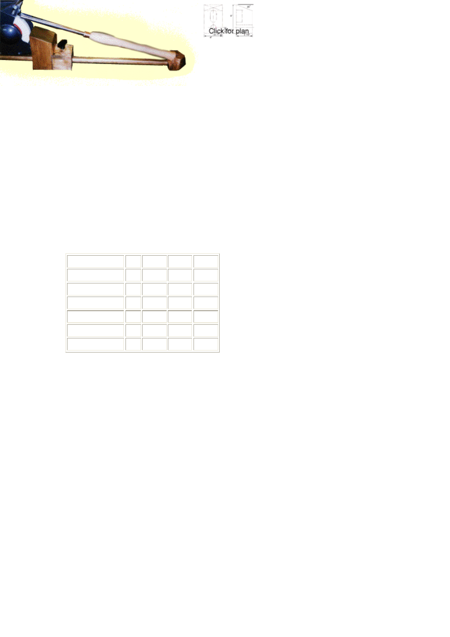
Turning Tool Rest and
Grinding Jig
By Larry Gawne
One of the hardest, and most frustrating, things that you have to do as a woodworker
is sharpen chisels. This seemingly simple task soon becomes one of the dreaded jobs
that you try to avoid for as long as possible. The problem is that sharpening your
chisels properly is difficult, and not sharpening them properly affects the quality of
your work dramatically. The sharpening fixture is a great time (and money) saver
while producing for the beginning turner a perfect cutting edge every time.
Construction
Tools required: Drill, saw, sander, router
Wood required: Maple (or any other scrap hardwood)
Description Qty
depth
width length
Tool rest block (1) 4"
4"
7"
Guide block
(1) 2 1/2" 3"
3"
Cover plate
(1) 3/4" 2 1/2" 3"
Clamp disc
(1) 1 3/8" 1 3/8" 1/2"
Vee tool rest
(1) 2"
2 1/2" 2 1/2"
Dowel
(1) 1"
1"
36"
To make it easier to comprehend, we have split this project into a number of distinct
parts that are assembled together at the end.
Tool Rest
The tool rest is a simple piece 4" x 4" x 6". The 6" dimension matches the distance
from the base to the center of the grinding wheel. Start by squaring off one end of the
block (the bottom of the block) and making sure the sides are square and parallel.
Next cut the 20 degree angle in the other end of the block (this is considered to be the
top). The total height of this block should match the height from the workbench to the
center of the grinding wheel (in this case 6").
The next step is to bore a 1 1/16" hole through the block. The center of this hole
should be 1 1/4" from the bottom of the block.
The next step depends on your brand of grinder. In this particular case, the grinder
had a protruding casting at the bottom of the grinding wheel housing. This meant that
the tool rest couldn't be positioned close enough to the grinder. To overcome this
problem, bore two 1 1/2" diameter holes on the back surface of the tool rest, drilling

to a depth of 1 1/2". Then chisel out the wood between these two holes to make an
oblong slot that will go around the casting on the grinder.
The tool rest is now finished and should be sanded down.
Clamp Block
This piece offered some interesting design challenges. As a result, you will notice that
the photo of the unit differs slightly from the design below. This is because with the
clamping knob on top (as in the original design), the knob sometimes got in the way
and prevented short chisels from sitting flat on the tool rest.
Drill a 1 1/16" diameter hole through the clamp block. The center of this hole should
be 1 1/4" from the bottom of the block (as with the tool rest above) and 1 1/2" from
the left hand side (in other words, in the center of the block).
Next, drill a 1 1/2" hole perpendicular to the above hole (see diagram). This hole
should be drilled to a depth of 1 1/4" so that it breaks through into the previous hole
that was drilled. This new hole will accommodate the clamping disc, which is
tightened against the main dowel (which runs through the 1 1/16" hole), thus
clamping the block into place.
Clamping Disc
The clamping disc is a 1 3/8" diameter by 1/2" long disc. After cutting this to shape,
roughly rout out a 1" diameter area in the middle of it to a depth of 1/16". Then, take a
thin metal disc and glue it into this routed out area (the knockout tabs from an
electrical box are ideal for this). The reason for doing this is to provide a solid metal
surface that won't yield when the unit is tightened.
Clamp Block Cover Plate
The clamp block cover is a 3/4" x 2 1/2" x 3" piece of hardwood or plywood. Drill a
hole to receive the 1/4" - 20 "T" nut for the clamp screw to work in. It is best to spot
face a area so the "T" nut is flush with the surface. When this is done, it is time to
assemble the clamping block.
To do this, screw a pan head screw into the "T", dropping the clamping disc into the
hole (metal insert up) and then attach the cover plate to the base block with screws.
Vee Block Tool Rest
This piece presented some challenges on how to make it. The best approach is to start
with a larger piece of 4 x 4 stock left over from the tool rest and then cut it to the final
dimensions at the end.

To cut the Vee pocket make up a router jig by making a internal 90 degree corner in a
piece of 1/4" plywood. Each leg of the 90 degree corner should be about 8" long.
Clamp this jig to the stock at a 45 degree angle and rout down the Vee pocket to a
depth of 1". Next, cut the block to its final dimension of 2 1/2" x 2" x 1/2".
Drill a 1/2" diameter hole to receive the narrow end of the dowel. This is drilled 1/2"
up and on the center of the Vee (see diagram).
Finally, cut the 45 degree corners off the back of the block and then sand the back
radius for appearance.
Dowel Rod Guide
The first step is to narrow down the last 1 1/4" of the dowel to a 1/2" radius. The
easiest way to do this is with a lathe, but you can get adequate results by using a knife
to whittle it down, then sanding to a smooth shape. Once you have done this, cut off
the end 1/4" so that you have a 1/2" diameter tenon that is 1" long.
The dowel has one flat side which is the result of shaving off 1/8" of the dowel. This
can either be done on a table saw or by using a planer (be it a machine or by hand).
Once this is done, glue the dowel into the Vee block, ensuring that the flat on the
dowel is perpendicular to the flat Vee pocket (the side of the Vee that your handle is
on).
Putting it all together
Final assembly consists of mounting the tool rest and clamp block assembly to the
plywood base for the grinder. Special attention should be given to assure that the
centerline of the dowel is aligned with the center of the grinding wheel and
perpendicular to the axis of the grinding wheel. Both these pieces were attached with
wood screws from underneath the plywood base plate. Finally, mount your grinder
and you are in business.
Document Outline
Wyszukiwarka
Podobne podstrony:
Lathe Turning Tips
89 1268 1281 Tool Life and Tool Quality Summary of the Activities of the ICFG Subgroup
93 1343 1362 Tool Failures Causes and Prevention
21 269 287 Effect of Niobium and Vanadium as an Alloying Elements in Tool Steels
Lynge Odeon A Design Tool For Auditorium Acoustics, Noise Control And Loudspeaker Systems
Knurling Tool Attachment for Taig Lathe
Jig For Frame And Panel Gluing
10 129 139 New Tool Steel for Warm and Hot Forging
84 1199 1208 The Influence of Steel Grade and Steel Hardness on Tool Life When Milling
2009 10 Jurassic Park Clonezilla Partition Clone and Backup Tool
56 793 814 Thermal Fatique of a Tool Steel Experiment and Numerical Simulation
87 1237 1248 Machinability and Tool Wear During the High Speed Milling of Some Hardened
48 671 684 Cryogenic Treatment and it's Effect on Tool Steel
74 1053 1066 Hard PVD Coatings and Their Perspectives in Forming Tool Applications
93 1343 1362 Tool Failures Causes and Prevention
Lesson Plan Receiving and Turning with the ball
więcej podobnych podstron