
(OWDOYOUDESIGN
!#OMPENDIUMOF-ODELS
BY(UGH$UBBERLY
$UBBERLY$ESIGN/FFICE
(ARRISON3TREET
3AN&RANCISCO#!


Everyone designs.
The teacher
arranging
desks
for a discussion.
The entrepreneur
planning
a business.
The team
building
a rocket.
3

4
Their results differ.
So do their goals.
So do the scales of their projects
and the media they use.
Even their actions
appear quite different.
What’s similar
is that they are designing.
What’s similar
are the processes
they follow.

5
Our processes
determine the quality
of our products.
If we wish to improve our products,
we must improve our processes;
we must continually redesign
not just our products
but also the way we design.
That’s why we study the design process.
To know what we do
and how we do it.
To understand it
and improve it.
To become
better
designers.

6
Introduction
In this book, I have collected over one-hundred descriptions
of design and development processes, from architecture,
industrial design, mechanical engineering, quality
management, and software development. They range from
short mnemonic devices, such as the 4Ds (defi ne, design,
develop, deploy), to elaborate schemes, such as Archer’s
9-phase, 229-step “systematic method for designers.”
Some are synonyms for the same process; others represent
differing approaches to design.
By presenting these examples, I hope to foster debate about
design and development processes.
How do we design?
Why do we do it that way?
How do we describe what we do?
Why do we talk about it that way?
How do we do better?
Asking these questions has practical goals:
- reducing risk (increasing the probability of success)
- setting expectations (reducing uncertainty and fear)
- increasing repeatability (enabling improvement)
Examing process may not benefi t everyone. For an individual
designer—imagine someone working alone on a poster—
focusing on process may hinder more than it helps. But
teaching new designers or working with teams on large
projects requires us to refl ect on our process. Success
depends on:
- defi ning roles and processes in advance
- documenting what we actually did
- identifying and fi xing broken processes
Ad hoc development processes are not effi cient and not
repeatable. They constantly must be reinvented making
improvement nearly impossible. At a small scale, the costs
may not matter, but large organizations cannot sustain them.
From this discussion, more subtle questions also arise:
How do we minimize risk while also maximizing creativity?
When must we use a heavy-weight process?
And when will a light-weight process suffi ce?
What is the place of interaction design within the larger
software development process?
What is the place of the software development process
within the larger business formation processes?
What does it mean to conceive of business formation as a
design process?

7
Origins
The oldest development process model I’ve seen dates
from about 1920 and describes how to develop a
battleship for the Royal Navy. Discussions about design
and development processes began in earnest shortly after
the second world war. They grew out of military research
and development efforts in at least three fi elds, operations
research, cybernetics, and large-scale engineering project
management.
Pre-war efforts to make radar an effective part of the British
air-defense system led to operations research, which
then matured into an academic discipline. Development
of automatic piloting devices and fi re-control systems for
aiming large guns led to servo-mechanisms and computing
devices, anticipating the emergence of cybernetics, one of
the roots of artifi cial intelligence. Large engineering projects
undertaken during the war and later cold-war projects, such
as the Atlas and Titan missile projects, demanded new
techniques to deal with increased scale and complexity.
The excitement of these new disciplines and the success of
these huge engineering projects captivated many people.
From operations research, cybernetics, and large-scale
engineering project management, academic designers
imported both methods and philosophy in what became
known as the design methods movement (1962-1972). Work
in the UK, at Ulm in Germany, and MIT and Berkeley in the
US sought to rationalize and systemize the design process.
Several designers attempted to codify the design process
and present it as a scientifi c method.
Somewhat parallel efforts occurred in the business world.
Stafford Beer and others applied systems thinking and
especially operations research to business problems.
During the 1950s, W. Edward Deming examined business
processes. His work led to the quality management
movement, which became popular in Japan and something
of a fad in the US in the 1980s. Its principles became
standard operating procedures in much of the business
world, becoming enshrined in ISO and six-sigma standards.
In the software world, interest in the development process
dates back at least to the IBM System 360, released in 1964.
In 1975, Fred Brooks, manager of OS/360, published The
Mythical Man Month, his “belated answer to [IBM Chairman]
Tom Watson’s probing question as to why programming is so
hard to manage.”
Today, software developers are still actively discussing
the question. Consultants seek to differentiate themselves
with proprietary processes. Software tools makers seek
standards around which they can build tools—a new twist on
codifying the design process.
Curious ties exists between the design methods world and
the software development world. One of the founders of
the design methods movement, Christopher Alexander,
co-wrote A Pattern Language. Alexander’s work on design
patterns in architecture contributed to thinking on design
patterns in software. In the 1970s, another important fi gure
in the movement, Horst Rittel, developed IBIS (Issues-Based
Information System) to support the design process. Rittel’s
research into IBIS is a precursor of today’s work on design
rationale.
But for the most part, designers, business managers, and
software developers appear to be unaware of practices and
thinking about process in the other disciplines. Even within
their own fi elds, many are unaware of much prior art.
The fi elds overlap, but so far as I know, no one has
attempted to bring together work from these three areas.
One of my goals is to cast each of these activities as design,
to show how their processes are similar, and to encourage
sharing of ideas between the disciplines.

8
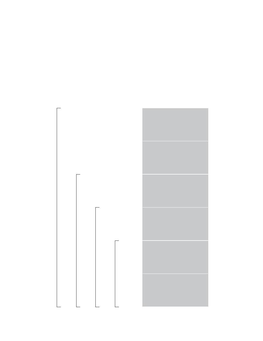
Measure twice
Cut once
Lab study
Pilot plant
Full-scale plant
Research
Development
Manufacturing
Sales
Ready
Aim
Fire

9
Contents
The carpenter’s adage,
the captain’s command,
the chemical engineer’s “scale-up” process,
the corporation’s departments—
the four phrases on the previous page—
have something in common.
Each is a sequence of steps.
Each is a process focused on achieving a goal.
Each suggests iteration and convergence.
Each is an analog of the design process.
This book presents many other descriptions of design and
development processes. I call these descriptions design
process models, distinguishing the description from the
activity it describes. I also combine design and development
into one category, because the distinction is without a
difference.
This collection is not exhaustive. Even so, organizing it
presents a challenge. At the end of the book are indices
organized by title, date, and author. In the body of the book
are threads but no strong narrative. I have paired models
where I see a connection. These pairings—and the entire
structure—are idiosyncratic. Thus, the book is more a
reference work than a primer.
11 Introducing
process
19 Analysis versus synthesis
29 Academic
models
61 Consultant
models
67 Software
development
82 Complex linear models
115 Cyclic models
132 Complete list of models
136 Chronological list
140 Author list
10
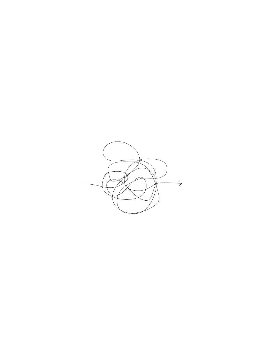
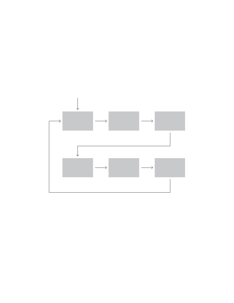
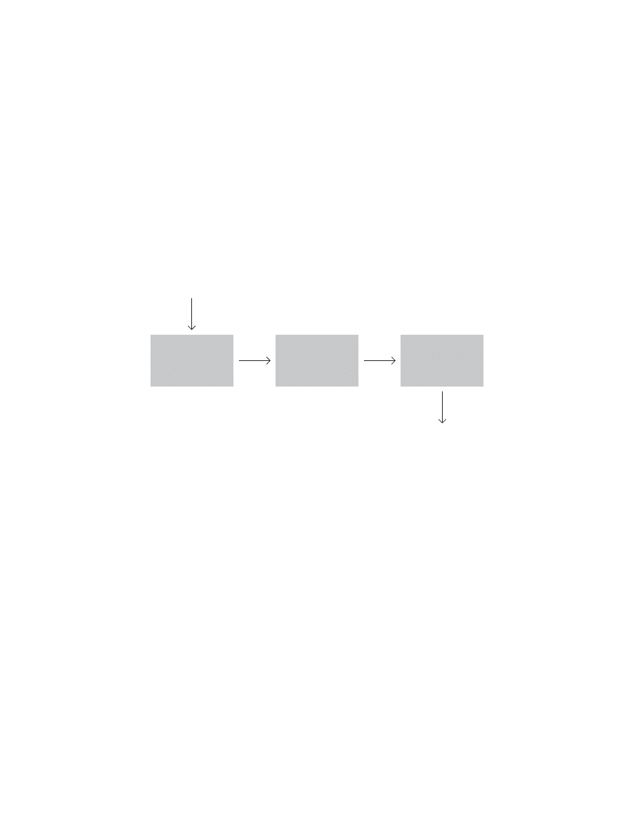
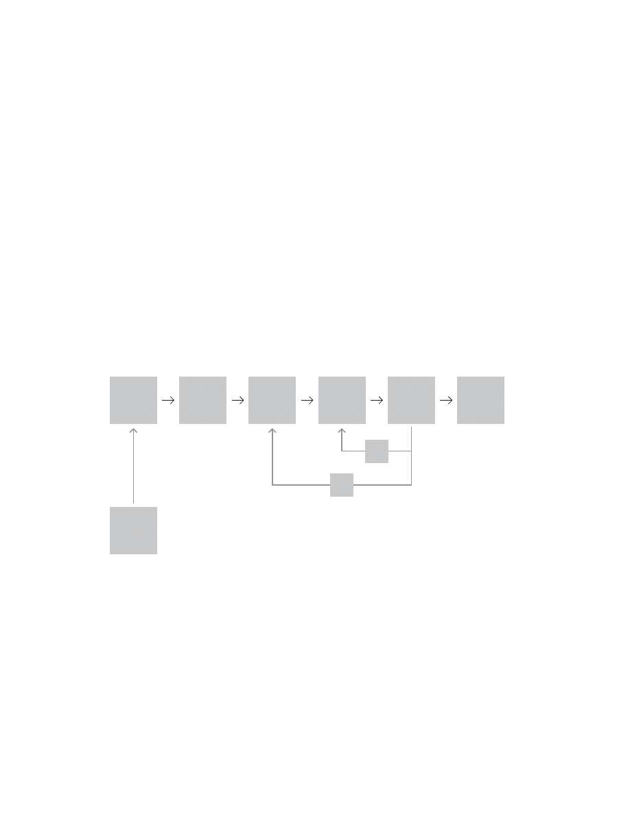
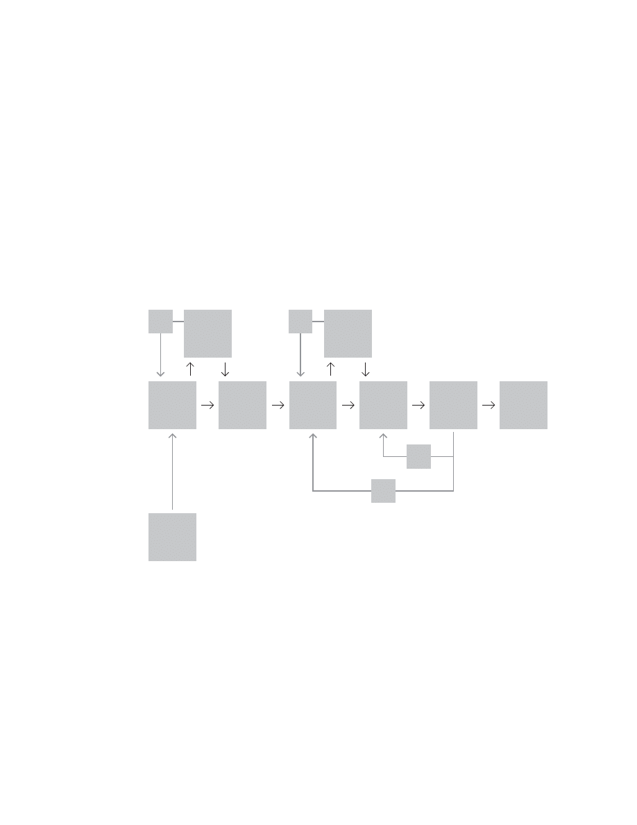
Design process
after Tim Brennan (~1990)
At an off-site for Apple Computer’s Creative Services de-
partment, Tim Brennan began a presentation of his group’s
work by showing this model. “Here’s how we work,” he said.
“Somebody calls up with a project; we do some stuff; and
the money follows.”
Brennan captures important aspects of the process:
- the potential for play
- its similarity to a “random walk”
- the importance of iteration
- its irreducible “black-box” nature

Introducing process
What is a process?
Where does it begin?
Where does it end?
How much detail is enough?
We begin with simple models
of the design process
and look at how they might be expanded
into useful frameworks.
11

12
)NPUT
0ROCESS
/UTPUT
Process archetype
A process must have input and output. Garbage in; garbage
out. (Good in; good out?) In between, something may hap-
pen—the process—a transformation. Sometimes, the trans-
formation is reducible to a mathematical function. Think
of using Photoshop’s curves function to lighten a photo.
One risk in using this framework is that it neatens a messy
world. It may promote an illusion of linearity and mecha-
nism—of cause and effect.
13
)NPUT
/UTPUT
0ROCESS
0ROCESS
0ROCESS
On the infi nite expandability of process models
Processes have a fractal quality. You can zoom in or out,
increasing or decreasing abstraction or specifi city. You can
add more detail—dividing phases into steps and steps into
sub-steps, almost infi nitely. Processes rarely have fi xed
beginnings or endings. You can almost always add steps
upstream or downstream.
An important step in managing any process is document-
ing it. That truism implies a process merely needs recording.
But documenting a process is like taking a photograph. The
author chooses where to point the camera—where to begin
mapping the process, where to end, what to put in, what to
leave out, how much detail to include.

14
!NALYSIS
3YNTHESIS
0ROCESS
)NPUT
/UTPUT
Design process archetype: Analysis, Synthesis
after Koberg and Bagnall (1972)
of design, two basic stages are necessary. First, we break
the situation or whole problem into parts for examination
(Analysis) and Second, we reassemble the situation based
on our understanding of improvements discovered in our
study (Synthesis).”
“When comparing many different problem-solving approach-
es it becomes necessary to search for their basic abstrac-
tions or common-denominators,” write Koberg and Bagnall.
“If you’ll try it yourself, we’re sure that the two “basic” stages
of analysis and synthesis will emerge; i.e., when consciously
solving problems or when creatively involved in the activity

15
0ROBLEM
%STABLISHING.EEDS
&ACTORS2ELATIONSHIPS0RINCIPLES&ORMS
3ATISFYING.EEDS
3OLUTION
Problem, Solution
after JJ Foreman (1967)
Foreman, like Koberg and Bagnall, casts design as problem-
solving. This stance is typical of the fi rst generation of the
design methods movement. Foreman introduces the idea of
needs. He also begins to sub-divide the process.

16
Expanding the two-step process
after Don Koberg and Jim Bagnall (1972)
In their classic book, The Universal Traveler, Koberg and Ba-
gnall (who taught in the College of Environmental Design at
Cal Poly in San Luis Obisbo) expand the archtypal two-step
process to three, then fi ve, and fi nally to seven steps.
They note “that ‘out of Analysis’ we derive an understanding
or concept that is then followed as a guideline in the rebuild-
ing or Synthesis stage.” Within the book’s “problem-solving”
frame, defi nition becomes problem defi nition, and they never
follow up on the idea of defi nition as concept or parti.
The synthesis phase becomes “ideate, select, implement,”
while the analysis phase remains intact. Finally, they add a
new phase at the beginning and another at the end.
ACCEPT
ANALYZE
DEFINE
IDEATE
SELECT
IMPLEMENT
EVALUATE
ANALYZE
DEFINE
IDEATE
SELECT
IMPLEMENT
ANALYSIS
DEFINITION
SYNTHESIS
ANALYSIS
SYNTHESIS

17
$IRECT$ESIGN
3TATE
0ROCESS
3TATE
3TATE
)NDIRECT$ESIGN
!NALYSIS
3TATE
!NALYSIS
'ENESIS
3YNTHESIS
3TATE
,IST
-ATRIX
3EMILATTICE
'ENESIS
3YNTHESIS
3CHEMATIC
3TATE
-ECHANICAL
$RAWING
-ODEL
!NALYSIS
0ROCESSES
)NTERVIEWS
0RIMARY
3ECONDARY
$ATA3EARCHES
&IELD2ESEARCH
3UPERSETS
#OMPETITION
#HANNELS
4ECHNOLOGY
#ONSUMERS
)SSUES
0OSITION
#ONTENT
.OMENCLATURE
$ESIGN
)MPLEMENTATION
3PECIALISTS
%NGINEERING
3TYLING
%RGONOMICS
!DVERTISING
"ROCHURES
#ATALOGS
$IRECT-AIL
'RAPHIC&ORMATS
)DENTITY%LEMENTS
#ONTROL5SER-ANUALS
,ANGUAGE
.OMENCLATURE
0ACKAGING
0OINT/F0URCHASE
4RADESHOWS
%TC
$EPARTMENTS
%NGINEERING
3TYLING
#ATALOG
0ACKAGING
!DVERTISING
0UBLIC2ELATIONS
4RADE3HOWS
5SER-ANUALS
$IRECT-AIL
#ORPORATE)TEMS
%TC
3TATE
)NFORMATION
'ATHERING
)NFORMATION
3TRUCTURING
0LAN
%VALUATE
0LAN
'ENESIS
3YNTHESIS
$ESIGN
3TATE
%VALUATE
$ESIGN
)MPLEMENT
Matching process to project complexity
after Jay Doblin (1987)
In his article, “A Short, Grandiose Theory of Design,”
Doblin presents a similar series of expanding processes.
Dobin’s notion of direct and indirect design echos Alexan-
der’s (1962) model of unselfconscious and self-conscious
design. Doblin’s third and fourth processes correspond to
Alexander’s third type of design, mediated design (my title).
(For more on Alexander’s model, see the next page.)

18
Unself-conscious and self-conscious design
after Christopher Alexander (1962)
5NSELFCONSCIOUS
#
&
#ONTEXT
&ORM
!CTUALWORLD
3ELFCONSCIOUS
#
&
#ONTEXT
&ORM
!CTUALWORLD
#
&
-ENTALPICTURE
-EDIATED
#
&
#ONTEXT
&ORM
!CTUALWORLD
#
&
-ENTALPICTURE
#
&
&ORMALPICTUREOF
MENTALPICTURE
In Notes on the Synthesis of Form, Alexander (1962)
described three situations in which designing may take
place. In the fi rst, a craftsman works directly and unself-
consciously through “a complex two-directional interaction
between the context C1 and the form F1, in the world itself.”
In the second, designing is separate from making. Form is
shaped “by a conceptual picture of the context which
the designer has learned and invented, on the one hand,
and ideas and diagrams and drawings which stand for
forms, on the other.” In the third, the designer also works
self-consciously, this time abstracting and formalizing
representations of the problem and solution so that he and
others may inspect and modify them.

Analysis
synthesis
evaluation
In 1962, Jones proposed this procedure
as a basic framework for design processes.
But what relationship do the steps have?
Are they discrete?
Sequential?
Overlapping?
This section compares several models.
While attention often focuses
on the analysis-synthesis dichotomy,
we might also consider other dichotomies:
serialist versus holist
linear versus lateral
top-down versus bottom-up
agile versus heavy-weight
pliant versus rigid
19

20
)NPUT
!NALYSIS
3YNTHESIS
/UTPUT
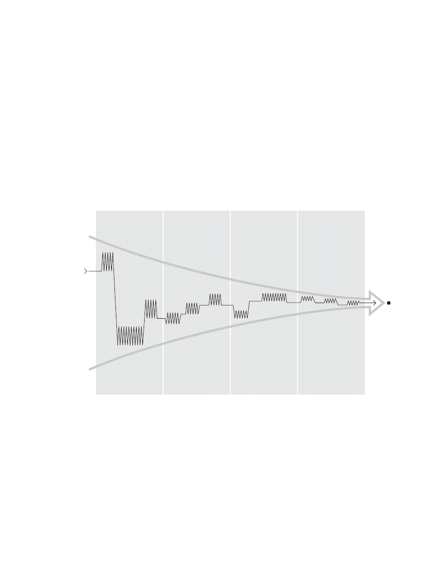
Oscillation
We may view the design process as an oscillation of the
designer’s attention between analysis and synthesis. Do
wave-length and amplitude remain constant? Do they vary
over time? What are the beginning and ending conditions?

21
0ROGRAMMINGCONCERNSFIVESTEPS
%STABLISH'OALS
7HATDOESTHECLIENTWANTTOACHIEVEAND7HY
#OLLECTANDANALYZE&ACTS
7HATDOWEKNOW7HATISGIVEN
5NCOVERANDTEST#ONCEPTS
(OWDOESTHECLIENTWANTTOACHIEVETHEGOALS
$ETERMINE.EEDS
(OWMUCHMONEYANDSPACE7HATLEVELOFQUALITY
3TATETHE0ROBLEM
7HATARETHESIGNIFICANTCONDITIONSAFFECTINGTHEDESIGNOFTHEBUILDING
7HATARETHEGENERALDIRECTIONSTHEDESIGNSHOULDTAKE
3CHEMATIC
0ROGRAM
0ROGRAM
$EVELOPMENT
3CHEMATIC
$ESIGN
$ESIGN
$EVELOPMENT
Programming and designing
after William M. Pena and Steven A. Parshall (1969)
This model comes from architecture, where programming
refers not to computers but to a phase of planning that
precedes design of a building. Pena and Parshall quote Web-
ster, “[Programming is] a process leading to the statement of
an architectural problem and the requirements to be met in
offering a solution.” They describe programming as “problem
seeking” and design as “problem solving.”
They note, “Programming IS analysis. Design IS synthesis.”
Pena and Parshall recommend “a distinct separation of pro-
gramming and design.” “The separation of the two is impera-
tive and prevents trial-and-error design alternatives.”

22
)NPUT
!NALYSIS
3YNTHESIS
"REAKING
INTOPARTS
2EASSEMBLING
INANEWWAY
/UTPUT
#ONVERGE
4RANSFORM
$IVERGE
Diverge / Converge vs Narrow / Expand
We may just as easily describe the process by reversing
the sequence (narrowing down, expanding out). Analyzing
a problem leads to agreement—to defi nition—a convergent
process. At that point, hopefully, the “miracle” of transfor-
mation occurs in which the solution concept arises. Then,
the designer elaborates that concept in greater and greater
detail—a divergent process.
Later, we see this question arise again in the section on
spiral models. Some (Souza) converge on a solution. Others
(Boehm) diverge from a center, suggesting the accumulation
of detail. (See pages 122-125.)
Often designers describe themselves as creating many
options (diverging) and then narrowing down their options
(converging). Alexander (1962) and other designers have
described analysis as a process of breaking a problem into
pieces—of “decomposing” it. Synthesis follows as re-or-
dering the pieces based on dependencies, solving each
sub-piece, and fi nally knitting all the pieces back together—
“recombining” the pieces. This decomposition-recombination
process also diverges and then converges.
23
/VERALLPROBLEM
3UBPROBLEMS
)NDIVIDUALPROBLEMS
)NDIVIDUALSOLUTIONS
/VERALLSOLUTION
3UBSOLUTIONS
Decomposition / recombination
after VDI 2221 (from Cross 1990)
VDI 2221 mirrors Alexander’s decomposition-recombination
process. Cross wrote, “The VDI Guideline follows a general
systemic procedure of fi rst analyzing and understanding the
problem as fully as possible, then breaking this into sub-
problems, fi nding suitable sub-solutions and combining
these into an overall solution.”
“This kind of procedure has been criticized in the design
world because it seems to be based on a problem-focused,
rather than a solution-focused approach. It therefore runs
counter to the designer’s traditional ways of thinking.” (For
another view of VDI 2221, see page 32.)

24
$IVERGENCE
#ONVERGENCE
$IVERGENCE
4RANSCEND%NVISION
4RANSFORM"Y$ESIGN
#ONVERGENCE
4HE-ODELOFTHE
&URTURE3YSTEM
!LTERNATIVE)MAGES
'ENESIS
!LTERNATIVE3OLUTIONS
4HE)MAGE
OFTHE&UTURE
3YSTEM
Dynamics of divergence and convergence
after Bela H. Banathy (1996)
Banathy’s model illustrates the iterative nature of the design
process, repeating the process of divergence and conver-
gence, analysis and sysnthesis.
In Banathy’s view, “We fi rst diverge as we consider a number
of inquiry boundaries, a number of major design options, and
sets of core values and core ideas. Then we converge,
as we make choices and create an image of the future
system. The same type of divergence-convergence operates
in the design solution space. For each of the substantive
design domains (core defi nition, specifi cations, functions,
enabling systems, systemic environment) we fi rst diverge
as we create a number of alternatives for each, and then
converge as we evaluate the alternatives and select the most
promising and most desirable alternative.”
25
$IVERGENCE
4RACKOF
DESIGNERS
ATTENTION
#ONVERGENCE
$IVERGENCE
#ONVERGENCE
3OLUTION
Overall, the design process must converge
after Nigel Cross (2000)
Cross notes, “Normally, the overall aim of a design strategy
will be to converge on a fi nal, evaluated and detailed design
proposal, but within the process of reaching that fi nal design
there will be times when it will be appropriate and necessary
to diverge, to widen the search or to seek new ideas and
starting points.
The overall process is therefore convergent, but it will contain
periods of deliberate divergence.”
Banathy’s and Cross’s models suggest cycles and are similar
to the iterative process of Marcus and Maver (see page 45)
and to the spirals of Boehm and others (see pages 122-125).

26
)NPUT
!NALYSIS
3YNTHESIS
/UTPUT
Gradual shift of focus from analysis to synthesis
after Bill Newkirk (1981)
Bill Newkirk fi rst taught me that synthesis begins at the
very beginning of a design project. Koberg and Bagnall
(1972) suggested that both analysis and synthesis continue
throughout a project. Designers may begin by focusing on
analysis and gradually shift their focus to synthesis.
Lawson (1990) notes, “Most of the maps of the design
process which we have looked at seem to resemble more
closely the non-designer, scientist approach than that of the
architects: fi rst analysis then synthesis. For the designers it
seems, analysis, or understanding the problem is much more
integrated with synthesis, or generating a solution.” He re-
ports studies by Eastman (1970) and Akin (1986) confi rming
this view. “Akin actually found that his designers were con-
stantly both generating new goals and redefi ning constraints.
Thus, for Akin, analysis is a part of all phases of design and
synthesis is found very early in the process.”

27
0ROBLEM
3OLUTION
VS
0ROBLEM
3OLUTION
VS
0ROBLEM
3OLUTION
Problem to solution: sequence, parallel process or loop?
Pena and Parshall (1969), Briggs and Havlick (1976), and
others, particularly in the early phases of the design methods
movement, described problem solving as a sequential activ-
ity. In this model, we must defi ne a problem before we can
solve it.
On the other hand, most people agree that a solution is
inherent in a problem. Having defi ned a problem, we’ve
defi ned or at least outlined the solution. Rittel and Webber
(1973) note, “The information needed to understand the
problem depends upon one’s idea for solving it.” (Italics are
theirs.) “Problem understanding and problem resolution are
concomitant to each other.” Attempting to solve a problem
(prototyping) may even improve our understanding of a prob-
lem—and thus change our defi nition.
28
,IFTFOOT
-OVELEG
,OWERFOOT
,EFTFOOT
,IFTFOOT
-OVELEG
,OWERFOOT
2IGHTFOOT
Walking process
after Lawson (1980)
Bryan Lawson offered this map “with apologies to those
design methodologists who like maps!” He notes that many
models of the design process are “theoretical and prescrip-
tive” rather than descriptions of actual behavior.

Academic models
Many teachers in the design fi elds,
engineering, and architecture
have developed models
of the design process
to help their students learn to design.
29

30
generation of a concept by the designer, usually after some
initial exploration of the ill-defi ned problem space.”
Cross’s model includes communication as a fi nal stage.
Archer (1963) may have been the fi rst to include communi-
cation as an explicit stage in a design process model. (See
page 98.)
Writing from an engineering perspective, Cross developed
this “simple descriptive model of the design process, based
on the essential activities that the designer performs. The
end-point of the process is the communication of a design,
ready for manufacture. Prior to this, the design proposal is
subject to evaluation against the goals, constraints and crite-
ria of the design brief. The proposal itself arises from the
%XPLORATION
'ENERATION
%VALUATION
#OMMUNICATION
Four stage design process
after Nigel Cross (2000)
31
!NALYSISOF0ROBLEM
.EED
#ONCEPTUAL$ESIGN
3TATEMENT
OF0ROBLEM
%MBODIMENTOF3CHEMES
$ETAILING
3ELECTED
3CHEMES
7ORKING
$RAWINGS
ETC
&EEDBACK
Engineering design process
after Michael J. French (1985)
French also wrote from an engineering perspective. He sug-
gested, “The analysis of the problem is a small but important
part of the overall process. The output is a statement of the
problem, and this can have three elements:
- a statement of the design problem proper
- limitations placed up the solution,
e.g. codes of practice, statutory requirements, customers’
standards, date of completions
- the criterion of excellence to be worked to.”
The conceptual design phase “takes the statement of the
problem and generates broad solutions to it in the form of
schemes. It is the phase that makes the greatest demands
on the designer, and where there is the most scope for strik-
ing improvements. It is the phase where engineering science,
practical knowledge, production methods and commercial
aspects need to be brought together . . .”
In the third phase, “schemes are worked up in greater detail
and, if there is more than one, a fi nal choice between them
is made. The end product is usually a set of general ar-
rangement drawings. There is (or should be) a great deal of
feedback from this phase to the conceptual design phase.
In the detailing phase, “a very large number of small but es-
sential points remain to be decided.”
32
VDI stands for Verein Deutscher Ingenieure, the professional
engineering society of Germany. Their guideline 2221 sug-
gests, “The design process, as part of product creation, is
subdivided into general working stages, making the design
approach transparent, rational and independent of a specifi c
branch of industry.”
The full process contains much more detail than the diagram
below shows. In practice, the process is less linear than the
diagram implies. “It is important to note that the stages do
not necessarily follow rigidly one after the other. They are
often carried out iteratively, returning to preceding ones, thus
achieving a step-by-step optimization.”
#LARIFYDEFINETHETASK
$ETERMINEFUNCTIONSTHEIRSTRUCTURES
3EARCHFORSOLUTIONPRINCIPLESTHEIRCOMBINATIONS
$IVIDEINTOREALIZABLEMODULES
$EVELOPLAYOUTSOFKEYMODULES
#OMPLETEOVERALLLAYOUT
0REPARINGPRODUCTIONOPERATINGINSTRUCTIONS
3PECIFICATION
&UNCTIONSTRUCTURE
0RINCIPLESOLUTION
-ODULESTRUCTURE
0RELIMINARYLAYOUTS
$EFINITIVELAYOUT
0RODUCTDOCUMENTS
4ASK
3TAGES
2ESULTS
4ASK
System approach to the design of technical systems and products
after Verein Deutscher Ingenieure (1987)
33
)NFORMATIONADAPTTHESPECIFICATION
#LARIFYTHETASK
%LABORATETHESPECIFICATION
)DENTIFYESSENTIALPROBLEMS
%STABLISHFUNCTIONSTRUCTURES
3EARCHFORSOLUTIONPRINCIPLES
#OMBINEANDFIRMUPINTOCONCEPTUALVARIANTS
%VALUATEAGAINSTTECHNICALANDECONOMICALCRITERIA
/PTIMIZEANDCOMPLETEFORMDESIGNS
#HECKFORERRORSANDCOSTEFFECTIVENESS
0REPARETHEPRELIMINARYPARTSLISTANDPRODUCTIONDOCUMENTS
&INALIZEDETAILS
#OMPLETEDETAILDRAWINGSANDPRODUCTIONDOCUMENTS
#HECKALLDOCUMENTS
$EVELOPPRELIMINARYLAYOUTSANDFORMDESIGNS
3ELECTBESTPRELIMINARYLAYOUTS
2EFINEANDEVALUATEAGAINSTTECHNICALANDECONOMICCRITERIA
3PECIFICATION
#ONCEPT
0RELIMINARYLAYOUT
$EFINITIVELAYOUT
$OCUMENTATION
4ASK
3OLUTION
5PGRADEANDIMPR
OVE
$ETAILDESIGN
%MBODIMENTDESIGN
#ONCEPTUALDESIGN
#LARIFICATION
OFTHETASK
/PTIMIZATIONOFTHEPRINCIPLE
/PTIMIZATIONOFTHELAYOUTANDFORMS
Design process
after Gerhard Pahl and Wolfgang Beitz (1984)
Cross recommends this model as “reasonably comprehen-
sive” but not obscuring “the general structure of the design
process by swamping it in the fi ne detail of the numerous
tasks and activities that are necessary in all practical design
work.” He seems to refer to Archer’s “Systematic method for
designers”. (See page 98.)
34
Communication involves describing “one or more potential
solutions to people inside or outside the design team.”
Lawson is critical, “it is hardly a map at all. . . . In short, all
this map does is to tell us that designers have to gather
information about a problem, study it, devise a solution and
draw it, though not necessarily in that order.”
Lawson presents this model from the RIBA (Royal Institute of
British Architects) practice and management handbook. Ac-
cording to the handbook, assimilation is “The accumulation
and ordering of general information specifi cally related to the
problem in hand.” General study is “The investigation of the
nature of the problem. The investigation of possible solutions
or means of solution.” Development is “refi nement of one
or more of the tentative solutions isolated during phase 2.”
!SSIMILATION
'ENERALSTUDY
$EVELOPMENT
#OMMUNICATION
Architect’s plan of work (schematic)
after the RIBA Handbook (1965)

35
"RIEFING
3KETCHPLANS
7ORKINGDRAWINGS
3ITEOPERATIONS
0ROJECTPLANNING
/PERATIONSONSITE
#OMPLETION
&EEDBACK
$ETAILDESIGN
0RODUCTIONINFORMATION
"ILLSOFQUANTITIES
4ENDERACTION
/UTLINEPROPOSALS
3CHEMEDESIGN
)NCEPTION
&EASIBILITY
Architect’s plan of work, (detailed)
after the RIBA Handbook (1965)
The handbook also contains another, more detailed plan of
work occupying 27 pages. The 12 main stages are described
below. Lawson criticizes this model as “a description not of
the process but of the products of that process. . . . It’s also
worth noting that the stages in the Plan of Work are closely
related to the stages of fee payment in the Conditions of
Engagement for Architects. So the Plan of Work may also
seen as part of a business transaction; it tells the client what
he will get, and the architect what he must do rather than
how it is done. In the detailed description of each section
the Plan of Work also describes what each member of the
design team (quantity surveyor, engineers etc) will do, and
how he will relate to the architect; with the architect clearly
portrayed as the manager and leader of this team. This
further reveals the Plan of Work to be part of the architectural
profession’s propaganda exercise to stake a claim as leader
of the multi-disciplinary building design team.”

36
5NDERSTANDINGTHEPROBLEM
$EVISINGAPLAN
#ARRYINGOUTTHEPLAN
,OOKINGBACK
#HECKTHERESULT
#ANYOUDERIVETHERESULTDIFFERENTLY
#ANYOUUSETHERESULTORTHEMETHODFORSOMEOTHERPROBLEM
#HECKEACHSTEP
#ANYOUSEECLEARLYTHATTHESTEPISCORRECT
#ANYOUPROVETHATITISCORRECT
&INDTHECONNECTIONBETWEENTHEDATAANDTHEUNKNOWN
$OYOUKNOWARELATEDPROBLEM
,OOKATTHEUNKNOWN
(EREISAPROBLEMRELATEDTOYOURSANDSOLVEDBEFORE
#OULDYOUUSEIT
#OULDYOURESTATETHEPROBLEM
#OULDYOURESTATEITSTILLDIFFERENTLY
'OBACKTODEFINITIONS
9OUSHOULDOBTAINEVENTUALLYAPLANOFTHESOLUTION
7HATISTHEUNKNOWN
7HATARETHEDATA
7HATISTHECONDITION
$RAWAFIGURE
)NTRODUCESUITABLENOTATION
3EPARATETHEVARIOUSPARTSOFTHECONDITION
#ANYOUWRITETHEMDOWN
Problem solving process
after George Polya (1945)
In 1945, George Polya wrote How to Solve It, an excellent
little book for students and teachers of mathematics. In it, he
describes a process for solving math problems, though one
might apply his process more generally.
Many in the design methods movement seem to have been
familiar with Polya’s book. Bruce Archer (1963-1964) men-
tions Polya in his booklet, Systemic method for designers.
Likewise, Maldonado and Bonsiepe (1964) also mention
Polya in their article “Science and Design.”
Thus Polya seems to have infl uenced the teaching of archi-
tecture, as may be seen in the “scientifi c problem solving
process” described on the following page.
37
They write, “the role of the environmental designer is to solve
human environmental problems by the creation and imple-
mentation of optimal physical form. . . . The scientifi c method
is the central process. [We have] borrowed the scientifi c
method from the traditional sciences and adapted it for the
development of optimal solutions. Termed the scientifi c
problem solving design process, it has been utilized to insure
an analytic, systematic, and precise approach to the solution
of man’s environmental malfunctions.”
Briggs and Havlick used this model for teaching design to
undergraduates at the University of Colorado’s College of
Environmental Design. The college’s name implies links to
environmental design faculties at Berkeley, San Luis Obispo,
and Ulm and thus to the design methods movement. Briggs
and Havlick shared the early movement’s desire to cast
design as a science.
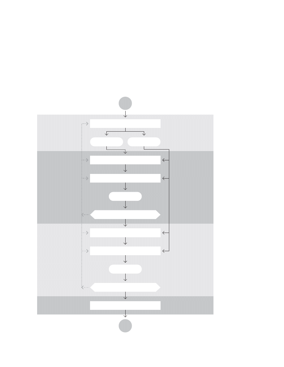
Scientifi c problem solving process
after Cal Briggs and Spencer W. Havlick (1976)
0ROBLEMSTATEMENT
5NFULFILLEDNEEDANDUNSATISFIEDNEED
)MPORTANCESTATEMENT
/BJECTIVE
0ARAMETERSYNTHESIS
3OLUTIONEVALUATION
&ULFILLEDACTIVITYANDSATISFIEDNEED
A!LTERNATIVEHYPOTHESIS
0ARAMETERDEVELOPMENT
A??????????????????????
B??????????????????????
C??????????????????????
D??????????????????????
B3ELECTEDHYPOTHESIS
"ACKGROUNDSTATEMENT
A"ACKGROUNDRESEARCH
4HEDELINEATIONOFAMALFUNCTIONINTHEHUMANENVIRONMENTWHICH
WASCREATEDBYTHEINABILITYTOPERFORMANEEDEDHUMANACTIVITY
4HEINVESTIGATIONINTOBACKGROUNDRESEARCHWHICHANSWERS
THEWHOWHATWHEREHOWWHENANDWHY
OFTHEPROBLEM4HISSTAGEALSOEXPLORES
APREVIOUSLYATTEMPTEDPHYSICALFORMSOLUTIONSAND
BALLCONTRIBUTINGCAUSESTOTHEPROBLEM
!STATEMENTWHICHDEMONSTRATESTHESIGNIFICANCEOFTHE
ENVIRONMENTALMALFUNCTIONINTERMSOFCRITICALHUMANNEEDSAND
WHATCONSEQUENCESMIGHTRESULTIFTHEPROBLEMWASNOTSOLVED
!STATEMENTOFTHEINTENDEDGOALSTHATWILLBEFULFILLEDBYTHE
SOLUTIONOFTHEPROBLEM
!RESEARCHEDASSUMPTIONWHICHASSERTSTHATIFACERTAINPHYSICAL
FORMAPPROACHISTAKENCERTAINRESULTSWILLENSUETHESATISFACTIONOF
UNMETNEED
4HEDEFINITIONANDORDERINGOFALLDESIGNCONSIDERATIONS
NECESSARYFORTHEDEVELOPMENTOFANOPTIMALSOLUTIONTOASTATED
PROBLEMIELEGALITYECONOMICFEASIBILITYECOLOGICALIMPLICATIONS
SHAPECOLORWEIGHTETC0ARAMETERSORVARIABLESARETHEFORM
DETERMININGCOMPONENTSWHICHCOMPRISETHEPROPOSED
HYPOTHESIS
4HESYSTEMATICOPTIMIZINGANDCOMPROMISINGOFORDEREDDESIGN
PARAMETERSINTOARESULTANTPHYSICALFORMSOLUTIONWHICHOPTIMALLY
ACHIEVESTHESTATEDOBJECTIVES)TSHOULDBESTATEDHERETHEhPHYS
ICALFORMvCOULDBETHEWRITINGOFENVIRONMENTALLEGISLATIONREDESIGN
ORCREATIONOFAPRODUCTORTHEFORMULATIONOFHOWASERVICECOULD
BEBESTPROVIDED
4HEIMPLEMENTATIONANDTESTINGOFTHEGENERATEDDESIGNSOLUTION
TODELINEATETHENEEDFORANYFURTHERMODIFICATIONSORRECYCLINGBACK
THROUGHTHESCIENTIFICPROBLEMSOLVINGPROCESS4HISEVALUATION
PROCESSPRECEDESIMPLEMENTATIONOFASOLUTION
4HEARROWSINTHEFLOWCHARTREVEALANIMPORTANTDIMENSIONOFTHE
PROBLEMSOLVINGDESIGNPROCESS!TEVERYPROCEDURALSTAGETHE
%NVIRONMENTAL$ESIGNERISABLETORECYCLEBACKTHROUGHTHEPROCESS
ONEORMORESTAGESIFMODIFICATIONSARENECESSARYTOIMPROVETHE
EVOLUTIONOFTHEFINALDESIGN
38
/BSERVATION
#ONCLUSION
4HEORY
(YPOTHESIS
%XPERIMENT
THEOC, a model of the scientifi c method
THEOC is an acronym for theory, hypothesis, experiment,
observation, conclusion — an easy way to remember an
outline of the scientifi c method. It approximates the process
with these steps:
- within a framework of a Theory
- generate a Hypothesis about a phenomenon
- run an Experiment to test the hypothesis
- Observe and record the results
- form a conclusion based on the relation of the observations
to the hypothesis.
- repeat as necessary

39
Claudia L’Amoreaux contributed the models below compar-
ing Maturana’s view of scientifi c explanation with his view of
the scientifi c method. L’Amoreaux points out that “Maturana
shows you not only don’t need objectivity to do science, you
can’t be objective. While the traditional pose of scientifi c
objectivity may be fi ne in some areas, we cannot understand
perception and the nervous system within that framework.”
Nor can we understand design that way.
Maturana writes, “scientifi c explanations are not valid in
themselves, they are generative mechanisms accepted as
valid as long as the criterion of validation in which
they are embedded is fulfi lled.”
“What do we explain?
We explain our experiences. . . .”
“What do we explain?
We explain our experiences
with the coherences of our experiences.
We explain our living with the coherences of our living.
Explanations are not so in themselves;
explanations are interpersonal relations.”
Criteria of Validation of Scientifi c Explanations (CVSE)
after Humberto Maturana (1987)
4HEDESCRIPTION
OFWHATANOBSERVERSHOULDDO
TOLIVETHEEXPERIENCE
TOBEEXPLAINED
#63%
3CIENTIFICMETHOD
4HEPROPOSITION
OFAGENERATIVEMECHANISM
4HEDEDUCTION
FROMALLTHEEXPERIENTIALCOHERENCES
OFTHEOBSERVERIMPLIEDIN
OFOTHERPOSSIBLEEXPERIENCES
THATHEORSHEMAYLIVE
ANDOFWHATHEORSHESHOULDDO
TOHAVETHEM
$OINGWHATHASBEENDEDUCTEDIN
ANDIFTHEOBSERVERLIVESTHEEXPERIENCESTHEREDEDUCED
THENISACCEPTEDASSCIENTIFICEXPLANATION
$OINGWHATHASBEENDEDUCEDIN
ANDIFTHEPREDICTEDNEWPHENOMENAOCCUR
THEHYPOTHESISORMODELPRESENTEDIN
ISCONFIRMED
4HEPREDICTIONOFOTHERPHENOMENA
ASSUMINGTHATISVALID
TOGETHERWITHTHEPROPOSITION
OFWHATTODO
TOSHOWTHEM
4HEPROPOSITION
OFTHEHYPOTHESISORMODEL
OFTHEREALITY
THATUNDERLIESTHEPHENOMENON
BEINGEXPLAINED
4HEDESCRIPTION
OFTHEPHENOMENON
TOBEEXPLAINED

40
According to the Buckminster Fuller Institute, Fuller began
formulating his theory of a comprehensive anticipatory de-
sign science as early as 1927. In 1950, he outlined a course,
which he taught at MIT in 1956 as part of the Creative Engi-
neering Laboratory. Students included engineers, industrial
designers, materials scientists, and chemists, representing
research and development corporations from across
the country.
The assertion that design is a science was most power-
fully articulated by Carnegie vv Herbert Simon (1969) in The
Sciences of the Artifi cial. Simon’s view is no longer fashion-
able. Most academic designers remain within Schools of Art.
Some, such as Banathy (1996), suggest design is a third way
of knowing distinct from the humanities and the sciences.
#HOOSE
PROBLEM
SITUATION
$EFINE
PROBLEMS
$EFINE
PREFERED
STATE
$ESCRIBE
PRESENT
STATE
$ESIGN
PREFERED
SYSTEM
$EVELOP
IMPLEMENTATION
STRATEGIES
$OCUMENT
PROCESS
#OMMUNICATE
PLAN
)NITIATELARGER
PLANNINGPROCESS
$EVELOPARTIFACTS
$EVELOP
EVALUATION
CRITERIA
)NVENTORY
ALTERNATIVES
Comprehensive anticipatory design science
after Buckminster Fuller (1950?)

41
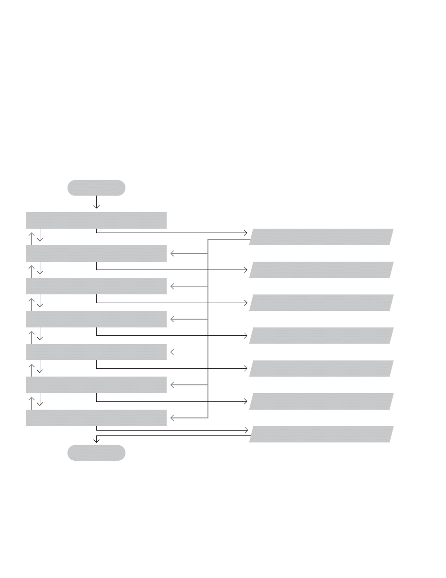
Design process and practice
after Richard Buchannan (1997)
Buchannan has a PhD in rhetoric and has taught design
for many years—also at Carnegie Mellon. Below, he pro-
vides a practical model for students. Note the repetition of
research, scenario building, and visualization in the three
middle phases.
6ISION
STRATEGY
"RIEF
#ONCEPTION
2EALIZATION
$ELIVERY
0HASES
/BJECTIVES
#HARACTERISTICACTIVITIES
$ISCOVERGOVERNINGIDEASANDCIRCUMSTANCES
IDENTIFYORGANIZATIONALVISIONSTRATEGY
PREPAREDESIGNBRIEF
)NDENTIFICATIONANDSELECTION
IDENTIFYANDSELECTTHEINITIALISSUES
FUNCTIONANDFEATURESTOBEADDRESSED
)NVENTIONANDJUDGMENT
INVENTPOSSIBLECONCEPTSOFTHEPRODUCT
JUDGEWHICHCONCEPTSAREVIABLE
$ISPOSITIONANDEVALUATION
PLANANDMAKEPROTOTYPEOFTHEPRODUCT
EVALUATEBYUSERTESTING
$IALOGUE
3TRATEGICPLANNING
3TRATEGICDESIGNPLANNINGWITHVISION
/FTHEPRODUCTDEVELOPMENTPROCESS
$ISCUSSION
2ESEARCH
3CENARIOBUILDING
6ISUALIZATION
0ROJECTPLANNING
$OCUMENTATION
2ESEARCH
"RAINSTORMING
3CENARIOBUILDING
%ARLYFREQUENTVISUALIZATION
$OCUMENTATION
2ESEARCH
3CENARIOBUILDINGREFINEMENT
6ISUALIZATION
#ONSTRUCTION
$OCUMENTATION
0RESENTATION
PRESENTPROTOTYPEDOCUMENTATION
ANDPRODUCTIONSPECIFICATIONS
/RALPRESENTATION
7RITTENPRESENTATION
0ROTOTYPEDEMONSTRATION
/BSERVATIONETC
3CRIBING
#ONCEPTMAPPING
/BSERVATION
#ONCEPTMAPPING
3KETCHING
-ODELLING
0ROTOTYPE
%VALUATE
0ROTOTYPE
%VALUATE
0ROTOTYPE
%VALUATE
42
Lawson, an architect, compares the creative process to the
design process. “The period of ‘fi rst insight’ (Kneller 1965)
simply involves the recognition that a problem exists and a
commitment is made to solving it. This period may itself last
for many hours, days or even years. The formulation of the
problem may often be a critical phase in design situations.
As we have seen, design problems are rarely initially entirely
clear and much effort has to be expended in understanding
them thoroughly.
The next phase of ‘preparation’ involves much conscious
effort to develop an idea for solving the problem. (MacKinnon
1976) As with our maps of the design process it is recog-
nized that there may be much coming and going between
these fi rst two phases as the problem is reformulated or even
completely redefi ned.
Yet all these writers emphasize here that this period of prepa-
ration involves deliberate hard work and is then frequently
followed by a period of ‘incubation’ which involves no appar-
ent effort, but which is often terminated by the emergence of
an idea (‘illumination’).
Some authors (MacKinnon 1976) explain this as unconscious
cerebration during the incubation period. The thinker is
unwittingly reorganizing and re-examining all his previous de-
liberate thoughts. Other writers suggest that by withdrawing
from the problem the thinker is then able to return with fresh
attitudes and approaches which may prove more productive
than continuing his initial thought development.
Once the idea has emerged all writers agree upon a fi nal
period of conscious verifi cation in which the outline idea is
tested and developed.”
&IRSTINSIGHT
0REPARATION
6ERIFICATION
)NCUBATION
)LLUMINATION
&ORMULATIONOFPROBLEM
#ONSCIOUSATTEMPTATSOLUTION
#ONSCIOUSDEVELOPMENT
.OCONSCIOUSEFFORT
3UDDENEMERGENCEOFIDEA
Creative process
after Bryan Lawson (1980)
43
'ENERATOR
#ONJECTURE
!NALYSIS
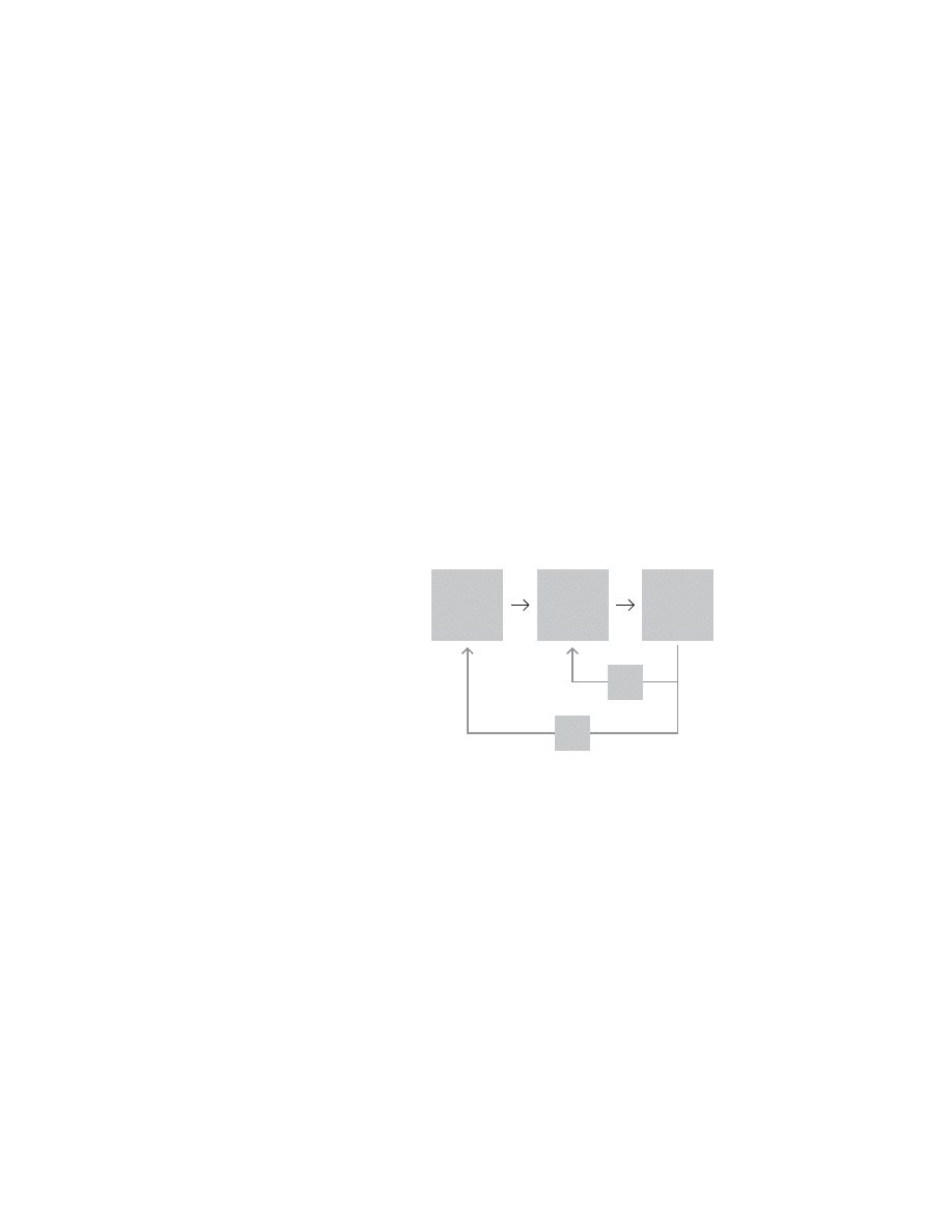
Primary generator
after Jane Darke (1978)
Lawson (1990) reports on Darke’s fi nding that at least some
architects begin the design process with a simple idea or
“primary generator”. “Thus, a very simple idea is used to nar-
row down the range of possible solutions, and the designer
is then able rapidly to construct and analyze a scheme. Here
again, we see this very close, perhaps inseparable, relation
between analysis and synthesis.”
Lawson suggests Darke’s model was anticipated by Hiller
et al (1972). Lawson summarizes Darke’s model, “In plain
language, fi rst decide what you think might be an important
aspect of the problem, develop a crude design on this basis
and examine it to see what else you can discover about the
problem.” Note the similarity to “hacking” in software devel-
opment.
44
Based on Darke’s research, Lawson suggests a looping
relationship between brief and analysis. One of the architects
Darke interviewed described the process, “. . . a brief comes
about through essentially an ongoing relationship between
what is possible in architecture and what you want to do,
and everything you do modifi es your idea of what is possible
. . . you can’t start with a brief and [then] design, you have to
start designing and briefi ng simultaneously, because these
two activities are completely interrelated.” (For another take
on this idea, see page 26.) Lawson points out that this may
be one reason “clients often seem to fi nd it easier to commu-
nicate their wishes by reacting to and criticizing a proposed
design, than by trying to draw up an abstract comprehensive
performance specifi cation.”
"RIEFING
!NALYSIS
3YNTHESIS
%VALUATION
Design process
after Jane Darke (1978)
45
!NALYSIS
3YNTHESIS
!PPRAISAL
$ECISION
!NALYSIS
3YNTHESIS
!PPRAISAL
$ECISION
!NALYSIS
3YNTHESIS
!PPRAISAL
$ECISION
/UTLINEPROPOSAL
3CHEMEDESIGN
$ETAILDESIGN
Design process
after Thomas A. Marcus (1969) and Thomas W Maver (1970)
Typically, in design process models evaluation follows
analysis and synthesis. Marcus and Maver substitute deci-
sion, casting the design process as a series of decisions.
They layer these decisions in three levels, outline proposals,
scheme design, and detail design. This iterative structure is
similar to that proposed by Banathy (1996) and Cross (2000).
(See pages 24 and 25.) It’s also similar to Boehm’s spiral.
(See page 122.) The three-level, four-step structure of this
model anticipates the structure of the AIGA model on the
next spread.

46
AIGA

47
$EFININGTHEPROBLEM
)NNOVATING
'ENERATINGVALUE
$EFININGTHE
PROBLEM
%NVISIONINGTHE
DESIREDENDSTATE
KNOWINGWHAT
VICTORYLOOKSLIKE
$EFININGTHE
APPROACHBYWHICH
VICTORYCAN
BEACHIEVED
)NCITINGSUPPORT
ANDTHENACTION
3EEKINGINSIGHT
TOINFORM
THEPROTOTYPING
OFTHESOLUTION
0ROTOTYPING
POTENTIAL
SOLUTIONS
$ELINEATINGTHE
TOUGHCHOICES
%NABLINGTHETEAM
TOWORK
ASATEAM
#HOOSINGTHE
BESTSOLUTION
THENACTIVATINGIT
-AKINGSURE
PEOPLEKNOWABOUT
YOURSOLUTION
3ELLING
THESOLUTION
2APIDLYLEARNING
ANDhTACKINGv
BASEDONYOUR
SUCCESSES
ANDFAILURES
Process of designing solutions
after Clement Mok and Keith Yamashita (2003)
American Institute of Graphic Arts (AIGA) president Clement
Mok enlisted Keith Yamashita to help the organization help
graphic designers explain what they do. Mok and Yamashita
produced a cheery little book describing a 12-step process
in which designers are “catalysts” for change.
The book casts design in terms of problem solving,
yet it also promises innovation.

48
$EFININGTHEPROBLEM
)NNOVATING
'ENERATINGVALUE
$EFININGTHE
PROBLEM
%NVISIONINGTHE
DESIREDENDSTATE
KNOWINGWHAT
VICTORYLOOKSLIKE
$EFININGTHE
APPROACHBYWHICH
VICTORYCAN
BEACHIEVED
)NCITINGSUPPORT
ANDTHENACTION
3EEKINGINSIGHT
TOINFORM
THEPROTOTYPING
OFTHESOLUTION
0ROTOTYPING
POTENTIAL
SOLUTIONS
$ELINEATINGTHE
TOUGHCHOICES
%NABLINGTHETEAM
TOWORK
ASATEAM
#HOOSINGTHE
BESTSOLUTION
THENACTIVATINGIT
-AKINGSURE
PEOPLEKNOWABOUT
YOURSOLUTION
3ELLING
THESOLUTION
2APIDLYLEARNING
ANDhTACKINGv
BASEDONYOUR
SUCCESSES
ANDFAILURES
.EEDOIL
'OTOIL
#ONTROL)RAQ
#REATEhAXISOFEVILv
ANDCLIMATEOFFEAR
!SKDAD
'RENADA0ANAMA
+UWAIT!FGHANISTAN
)NSPECTIONSVERSUS
OVERWHELMINGFORCE
h9OUAREEITHERWITHUS
ORAGAINSTUSv
7AR
h"OMBSAWAYv
#ALL2UPERT
AND(ALLIBURTON
7EAPONSOF
MASSDESTRUCTION
,IBERATINGTHE
PEOPLEOF)RAQ
Case study, using the AIGA process in Iraq
by Nathan Felde
AIGA has tried to use its 12-step model as a structure for
organizing case studies. Nathan Felde provided an example.

49
$ISCOVERINGTHEOPPORTUNITY
/BTAININGTHECONTRACT
'ETTINGPAID
!CQUIRING
ADISTINCTIVE
PERSONA
0RACTICING
CHARMUNTIL
CHARISMA
ISACHIEVED
#IRCULATING
AMONGSTTHE
RIGHTPEOPLE
,ISTENINGFOR
DEVELOPING
CHANGESIN
STATUSQUO
2AISINGQUESTIONS
THATONLYYOU
CANANSWER
%LIMINATINGOPTIONS
OTHERTHAN
YOURSERVICES
0RESENTING
THEPROPOSAL
WHILEAPPEARING
UNAVAILABLE
0ROMISINGMORE
THANTHECONTRACT
REQUIRES
$ISCOVERING
INSURMOUNTABLE
DIFFICULTIES
&INDINGSOMEONE
ONCLIENTSIDE
TOBLAME
2ESCUING
CLIENTWITH
BIGGERPROPOSAL
!NNOUNCING
SUCCESSWITH
FIRSTSTAGE
What the AIGA didn’t tell you
by Nathan Felde
Felde also offered an alternative version of the 12-step
process, acknowledging aspects of the AIGA’s function
(and that of other professional organizations) which few
bring up in public.

50
Alice Agogino
$EFINE
0ROTOTYPE
%VALUATE
51
$ESIGN
"UILD
4EST
$ESIGN
%RRORS
&AB
%RRORS
Design, build, test
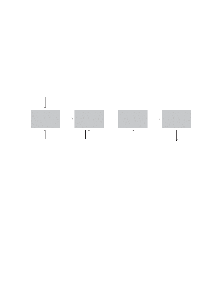
after Alice Agogino (1 of 3)
This model is the fi rst in a series of three developed by
Alice Agogino for NASA’s Jet Propulsion Laboratory (JPL) at
California Institute of Technology. Agogino is a professor of
mechanical engineering at UC Berkeley.
In the fi rst step, Agogino presents a variation on the
classic goal-action feedback loop. (See page 117.)
Of course, design-build-test is also analogous to defi ne-
prototype-evaluate. (See facing page.)
52
$ESIGN
"UILD
4EST
/PERATE
#ONCEIVE
3ELL
$ESIGN
%RRORS
&AB
%RRORS
3CIENCE5SE
3CENARIO
Design, build, test
after Alice Agogino (2 of 3)
In the second step, Agogino places the original design-build-
test process in the context of a larger project.
53
$ESIGN
"UILD
4EST
/PERATE
#ONCEIVE
-ODEL
4EST-ODEL
-ODEL
4EST-ODEL
3ELL
$ESIGN
%RRORS
&AB
%RRORS
3CIENCE5SE
3CENARIO
!RCHI
TECTURAL
%RRORS
$ESIGN
%RRORS
Design, build, test
after Alice Agogino (3 of 3)
In the last step, Agogio adds feedback loops with early tests
of models in order to “fi nd errors faster.”
54
3PECIFICATION!NALYSISOF0RODUCT%NVIRONMENT
$ETERMINATIONOF/VERALL&UNCTION3TRUCTURE
$ETERMINATIONOF3PECIAL&UNCTION3TRUCTURE
#OMPARISONOF3PECIFIEDAND!CTUAL&UNCTIONS
#OMPARISON
!CTUAL3PECIFIED&UNCTIONVS!CTUAL3PECIFIED#OST
&ORM$ESIGNAND-ATERIAL3ELECTION
$ESIGNFOR0RODUCTION
0RODUCTION$RAWINGS
4ASK
0RODUCT
3IMPLIFIED&UNCTION
!CTUAL&UNCTION
!CTUAL&UNCTION
!CTUAL#OST
4ECHNICAL2EQUIREMENTS
AND3PECIFIED#OSTS
-ECHANICAL%NGINEERING
4ASK&ORMULATION0HASE
&UNCTIONAL0HASE
&ORM$ESIGN0HASE
2ESULT
Mechanical engineering design process
after students at UC Berkeley Institute of Design (BID)
Agogino sometimes asks her students to diagram the design
process—an interesting way to begin to understand how stu-
dents (and others) understand things. Below is an example
from one of her classes.
55
New product development process
after Steven D. Eppinger and Karl T. Ulrich (1995)
)DENTIFY
#USTOMER
.EEDS
%STABLISH
4ARGET
3PECIFICATIONS
'ENERATE
0RODUCT
#ONCEPTS
0ERFORM%CONOMIC!NALYSIS
"ENCHMARK#OMPETITIVE0RODUCTS
"UILDAND4EST-ODELSAND0ROTOTYPES
-ISSION
3TATEMENT
$EVELOPMENT
0LAN
3ELECT
0RODUCT
#ONCEPTS
4EST0RODUCT
#ONCEPTS
3ET&INAL
3PECIFICATIONS
0LAN
$OWNSTREAM
$EVELOPMENT
4ECHNICAL0OSSIBILITIES
0ROTOTYPING#YCLES
#USTOMER0REFERENCES
Alice Agogino introduced me to Eppinger and Ulrich’s model
of the product development process. It provides a useful
outline, but does not capture the “messy” iteration typical of
much product development work.

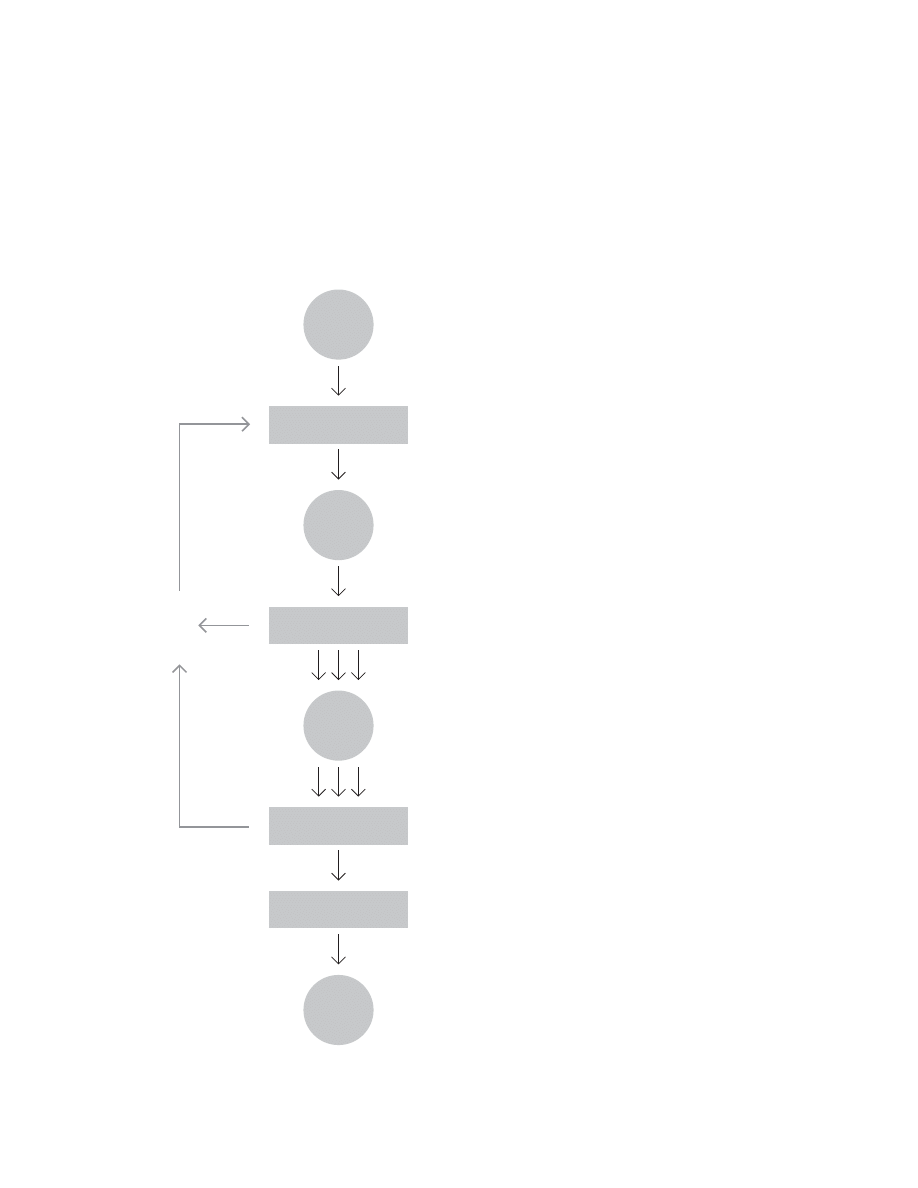
56
John Chris Jones
57
0ROBLEMSTRUCTUREPERCEIVED
ORTRANSFORMED
$ESIGNSITUATIONEXPLORED
"RIEFISSUED
!LTERNATIVEDESIGNSEVALUATED
ANDFINALDESIGNSELECTED
3UBSOLUTIONSCOMBINED
INTOALTERNATIVEDESIGNS
"OUNDRIESLOCATED
SUBSOLUTIONSDESCRIBED
ANDCONFLICTSIDENTIFIED
4ECHNOLOGICAL#HANGE
OR3OCIOTECHNICALINNOVATION
3YSTEM$ESIGNING
$ESIGNBY$RAWING
#RAFT%VOLUTION
Design process
after John Chris Jones (1970)
Along with Christopher Alexander and Bruce Archer, John
Chris Jones was one of the pioneers of the design methods
movement. Jones fi rst published Design Methods in 1970.
He included several models of design and the design pro-
cess. I have included three in this section.
Jones used the model below for classifying and selecting
design methods. Designers might use one or more meth-
ods to move from one step to another. Jones notes that
the steps decrease in generality and increase in certainty.
Jones also provides a scale for describing the applicable
range of a method. (See the left side of the diagram.) We
may also apply his scale to the scope of problem being un-
dertaken. In this way, Jones’s scale is similar to the models
of design scope described by Doblin and Alexander. (See
pages 17-18.)
58
$EFINE%LEMENT
$EFINE&UNCTION
#ONSIDER!LTERNATIVES
0ARTIAL3UBSTITUTION
2EDUCTION
!NALYSISOF#OST
!NALYSISOF#OST
!NALYSISOF6ALUE
.EW#ONCEPTS
#OMBINE7ITH
/THER%LEMENTS
4ECHNICAL!NALYSIS
0RELIMINARY3ORTING
3ELECTION
0RESENTATION
$EFINITION0HASE
%XISTING)DEA
%LIMINATE&UNCTION.OT2EQUIRED
2EJECT3OME.OT&EASIBLE
2EJECT3OME4ECHNICAL2EASONS
2EJECT3OME
#OST2EASONS
#REATIVE0HASE
.EW)DEAS
!NALYSISAND3ELECTION
"EST)DEA
0RESENTATION
3ELLINGTHE)DEA
&INAL!NALYSIS
OF#OST
Value analysis
after John Chris Jones (1970)
Jones described value analysis as a design method, one
aimed “to increase the rate at which designing and manufac-
turing organizations learn to reduce the cost of a product.”
He saw it as applying to the design of an element within a
larger system. Yet his value analysis process (as he dia-
grammed it) is itself a sort of design process—albeit with a
special emphasis on cost. This example of a design process-
nested within a design process nicely illustrates the recursive
nature of designing.
59
3PECIFY)NPUTSAND/UTPUTSOF3YSTEM
3PECIFY&UNCTIONSOF3YSTEM#OMPONENTS
!LLOCATE&UNCTIONSTO-ACHINESORTO(UMANS
#HECK3YSTEMFOR)NTERNAL
AND%XTERNAL#OMPATIBILITY
3PECIFY-ACHINE
0ERFORMANCE
3PECIFY(UMAN
0ERFORMANCE
$ESIGN-ACHINE
#OMPONENTS
$ESIGN-AN-ACHINE
)NTERFACES
$ESIGN*OB
!IDS
$ESIGN4RAINING
0ROCEDURES
(UMAN&ACTORS$ESIGN
Man-machine system designing
after John Chris Jones (1970)
Jones also described man-machine system designing as a
design method, one aimed “to achieve internal compatibility
between the human and machine components of a system,
and external compatibility between the system and the envi-
ronment in which it operates.”
This method, too, is a sort of design process. Jones notes
“the diagram should not be taken to imply a linear sequence
of stages. The specifi cations in each box can be attended to
in any order and will require many cross-references before
they are complete.” He suggests deliberately reversing “the
traditional sequence of machine-fi rst-people-second” design.
He proposes beginning with training procedures, working out
the man-machine interface, and then designing the machine
to support the desired training and interface.

60
Eight phases of a project
Sometimes presented as six phases of a project
People have passed variations of this project parody around
for years. Lawson sites an example seen on a wall of the
Greater London Council Architects Department in 1978.
More recently, Harold Kerzner offered the variation below.
One reason these parodies are popular may be that they
contain a large measure of truth.
0ROJECT)NITIATION
7ILD%NTHUSIASM
$ISILLUSIONMENT
#HAOS
3EARCHFORTHE'UILTY
0UNISHMENTOFTHE)NNOCENT
0ROMOTIONOF.ON0ARTICIPANTS
$EFINITIONOF2EQUIREMENTS

Consultant models
A few consultancies publish their processes.
Some fi rms see their processes
as a competitive advantage
and thus keep them proprietary.
Some fi rms operate without processes,
but who would admit such a thing?
61

62
4D software process
and variations
Defi ne
Design
Develop
Deploy
Defi ne
Design
Develop
Deploy
Debrief
Imirage
Defi ne
Design
Develop
Deploy
Dedicate
Bonns
Defi ne
Design
Develop
Deploy
Do Business
Q4-2
Defi ne
Design
Develop
Deploy
Enhance
Satoria
Defi ne
Design
Develop
Deploy
Maintain
Chris Brauer
Diagnose
Defi ne
Design
Develop
Deploy
Muirmedia
Discover
Defi ne
Design
Develop
Deploy
D5tech et al.
Discover
Defi ne
Design
Develop
Deploy
Defend
Dillon Group
Discover
Defi ne
Design
Develop
Deploy
Denouement
Cris Ippolite
Engagement Discovery Defi ne
Design
Develop
Deploy
Team 1
Plan
Defi ne
Design
Develop
Deploy
Conclude
Proxicom
Analyze
Defi ne
Design
Develop
Deploy
Assess
Maintain
Hbirbals
Defi ne
Design
Develop
Test
Deploy
Manage
Borland
Inform Defi ne
Detail
Design
Develop
Deploy
Phoenix Pop
The 4D software process, (defi ne, design, develop, deploy)
gained wide popularity among consultants developing web-
sites during the internet boom. One company, Information
Systems of Florida (SF) claims to have trademarked the
four steps. The phrase is useful as a mnemonic device,
but the wide range of variations suggests something is
missing, for example, feedback and iteration. Author and
date unknown.

63
5SER
4ECHNICAL$ESIGN
$ESIGN
2EQUIREMENTS
!RCHITECTURE
2OAD-AP
$EFINITION
3COPE$OCUMENT
$ISCOVERY
#ONTINUOUS)NNOVATION
#ONTINUOUS2EFINEMENT
0ROJECT-ANAGEMENT
2EQUIREMENTS3COPE#HANGE-ANAGEMENT
#ONFIGUREMENT-ANAGEMENT
2EVIEWED
5NIT4ESTED
3OURCE#ODE
$EVELOPMENT
4ESTED0RODUCT
4ESTING
-AJOR$ELIVERABLES
,IFE#YCLE0ROCESSES
#ONTINUOUS0ROCESSES
!PPLICATION
-ANAGEMENT
IT consulting process overview
after Mindtree Consulting
Mindtree places the 4D process in a larger context, linking
each step to deliverables and related processes. The pairing
of process steps and deliverables in a matrix is an important
and recurring framework or archetype.

64
Other models
Studio Archetype, 1998
Defi nition
Concept
Creation
Implementation
Cheskin, 2004
Discover Identify
Validate
Articulate
Frog, 2004
Product Lifecycle Phases
Conceptual Design
Detailed Design
Procurement/Production
Operations/Support
Product Design
Project Defi nition
Product Defi nition
Product Development
Product Engineering
Production
Brand & Space Process
Investigation
Concept Development
Concept Refi nement/Validation
Implementation
Digital Media Process
Investigation Exploration
Defi nition
Implementation
Integration/Testing
Launch
This page presents a sampling of design process models
from leading consultancies. They resemble the 4D model.
On the facing page is IDEO’s design process as described
in Business Week. IDEO is a large (by design standards)
multidisciplinary design consultancy.

65
IDEO (2004)
/BSERVATION
)$%/SCOGNITIVEPSYCHOLOGISTSANTHROPOLOGISTS
ANDSOCIOLOGISTSTEAMUPWITHCORPORATECLIENTSTO
UNDERSTANDTHECONSUMEREXPERIENCE
"RAINSTORMING
!NINTENSEIDEAGENERATINGSESSIONANALYZINGDATA
GATHEREDBYOBSERVINGPEOPLE%ACHLASTSNOMORETHAN
ANHOUR2ULESOFBRAINSTORMINGARESTRICTANDARE
STENCILEDONTHEWALLS
2APIDPROTOTYPING
-OCKINGUPWORKINGMODELSHELPSEVERYONEVISUALIZE
POSSIBLESOLUTIONSANDSPEEDSUPDECISIONMAKINGAND
INNOVATION
2EFINING
!TTHISSTAGE)$%/NARROWSDOWNTHECHOICESTO
AFEWPOSSIBILITIES
)MPLEMENTATION
"RING)$%/SSTRONGENGINEERINGDESIGNANDSOCIAL
SCIENCECAPABILITIESTOBEARWHENACTUALLYCREATINGA
PRODUCTORSERVICE
4APALLRESOURCES
)NVOLVE)$%/SDIVERSEWORKFORCEFROMCOUNTRIESTO
CARRYOUTTHEPLANS
4HEWORKFORCE
%MPLOYEESHAVEADVANCEDDEGREESINDIFFERENTKINDSOFENGINEERING
MECHANICALELECTRICALBIOMECHANICALSOFTWAREAEROSPACEANDMANUFACTURING
-ANYAREEXPERTSINMATERIALSSCIENCECOMPUTERAIDEDDESIGNROBOTICSCOMPUTER
SCIENCEMOVIESPECIALEFFECTSMOLDINGINDUSTRIALINTERACTIONGRAPHICANDWEB
INFORMATIONFASHIONANDAUTOMOTIVEDESIGNBUSINESSCOMMUNICATIONSLINGUISTICS
SOCIOLOGYERGONOMICSCOGNITIVEPSYCHOLOGYBIOMECHANICSARTTHERAPYETHNOLOGY
MANAGEMENTCONSULTINGSTATISTICSMEDICINEANDZOOLOGY
(ERESHOWITSDONE
"RAINSTORM
INARAPIDFASHIONTOWEEDOUTIDEASANDFOCUSONTHEREMAINING
BESTOPTIONS
&OCUSPROTOTYPING
ONAFEWKEYIDEASTOARRIVEATANOPTIMALSOLUTIONTOAPROBLEM
%NGAGETHECLIENT
ACTIVELYINTHEPROCESSOFNARROWINGTHECHOICES
"EDISCIPLINED
ANDRUTHLESSINMAKINGSELECTIONS
&OCUS
ONTHEOUTCOMEOFTHEPROCESSREACHINGTHEBESTPOSSIBLESOLUTIONS
'ETAGREEMENT
FROMALLSTAKEHOLDERS4HEMORETOPLEVELEXECUTIVESWHOSIGNOFF
ONTHESOLUTIONTHEBETTERTHECHANCESOFSUCCESS
3OMEGUIDELINES
-OCKUPEVERYTHING
)TISPOSSIBLETOCREATEMODELSNOTONLYOFPRODUCTS
BUTALSOOFSERVICESSUCHASHEALTHCAREANDSPACESSUCHASMUSEUMLOBBIES
5SEVIDEOGRAPHY
-AKESHORTMOVIESTODEPICTTHECONSUMEREXPERIENCE
'OFAST
"UILDMOCKUPSQUICKLYANDCHEAPLY.EVERWASTETIMEON
COMPLICATEDCONCEPTS
.OFRILLS
-AKEPROTOTYPESTHATDEMONSTRATEADESIGNIDEAWITHOUTSWEATING
OVERTHEDETAILS
#REATESCENARIOS
3HOWHOWAVARIETYOFPEOPLEUSEASERVICEINDIFFERENTWAYS
ANDHOWVARIOUSDESIGNSCANMEETTHEIRINDIVIDUALNEEDS
"ODYSTORM
$ELINEATEDIFFERENTTYPESOFCONSUMERSANDACTOUTTHEIRROLES
$EFERJUDGMENT
$ONTDISMISSANYIDEAS
"UILDONTHEIDEASOFOTHERS
.OhBUTSvONLYhANDSv
%NCOURAGEWILDIDEAS
%MBRACETHEMOSTOUTOFTHEBOXNOTIONSBECAUSE
THEYCANBETHEKEYTOSOLUTIONS
'OFORQUANTITY
!IMFORASMANYNEWIDEASASPOSSIBLE)NAGOODSESSION
UPTOIDEASAREGENERATEDINMINUTES
"EVISUAL
5SEYELLOWREDANDBLUEMARKERSTOWRITEONBIGINCHBYINCH
0OSTITSTHATAREPUTONAWALL
3TAYFOCUSEDONTHETOPIC
!LWAYSKEEPTHEDISCUSSIONONTARGET
/NECONVERSATIONATATIME
.OINTERRUPTINGNODISMISSINGNODISRESPECT
NORUDENESS
3OMEOF)$%/STECHNIQUES
3HADOWING
/BSERVINGPEOPLEUSINGPRODUCTSSHOPPINGGOINGTOHOSPITALS
TAKINGATRAINUSINGTHEIRCELLPHONES
"EHAVIORALMAPPING
0HOTOGRAPHINGPEOPLEWITHINASPACESUCHASAHOSPITAL
WAITINGROOMOVERTWOORTHREEDAYS
#ONSUMERJOURNEY
+EEPINGTRACKOFALLTHEINTERACTIONSACONSUMERHASWITHIN
APRODUCTSERVICEORSPACE
#AMERAJOURNALS
!SKINGCONSUMERSTOKEEPVISUALDIARIESOFTHEIRACTIVITIES
ANDIMPRESSIONSRELATINGTOAPRODUCT
%XTREMEUSERINTERVIEWS
4ALKINGTOPEOPLEWHOREALLYKNOWORKNOWNOTHING
ABOUTAPRODUCTORSERVICEANDEVALUATINGTHEIREXPERIENCEUSINGIT
3TORYTELLING
0ROMPTINGPEOPLETOTELLPERSONALSTORIESABOUTTHEIR
CONSUMEREXPERIENCES
5NFOCUSGROUPS
)NTERVIEWINGADIVERSEGROUPOFPEOPLE4OEXPLOREIDEASABOUT
SANDALS)$%/GATHEREDANARTISTABODYBUILDERAPODIATRISTANDASHOEFETISHIST
66
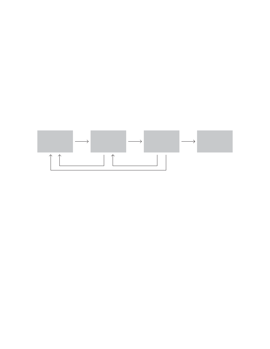
As proposed by the project sponsor
As specifi ed in the project request
As designed by the senior analyst
As produced by the programmers
As installed at the user’s site
What the user wanted

Software
development
models
Development processes
remain a topic of heated discussion
in the software development world.
This section provides an overview
of some of the prominent models.
67
68
Waterfall lifecycle
after Philippe Kruchten (2004)
2EQUIREMENTS
$ESIGN
#ODING
4ESTING
2EQUIREMENTS
$ESIGN
#ODING
4ESTING
2EQUIREMENTS
$ESIGN
#ODING
4ESTING
2EQUIREMENTS
$ESIGN
#ODING
4ESTING
The essence of the “waterfall” approach is getting one stage
“right” before moving on to the next. Output (a “deliverable
document”) from one phase serves as input (requirements)
to the next phase. Kruchten noted, “Of paramount impor-
tance for certain projects is the issue of freezing the require-
ments specifi cations (together with some high-level design)
in a contractual arrangement very early in the lifecycle, prior
to engaging in more thorough design and implementation
work. This is the case when an organization has to bid a
fi rm, fi xed price for a project.” Per Kroll (2004) noted, “Many
design teams would view modifying the design after Stage 1
as a failure of their initial design or requirements process.”
Kroll admitted, “In practice, most teams use a modifi ed
waterfall approach, breaking a project down into two or more
parts, sometimes called phases or stages. This helps to
simplify integration, get testers testing earlier, and provide an
earlier reading on project status. This approach also breaks
up the code into manageable pieces and minimizes the inte-
gration code . . .”
According to Kruchten, “we inherited the waterfall lifecycle
from other engineering disciplines, where it has proven very
effective. It was fi rst formally described by Winston Royce
in 1970.”
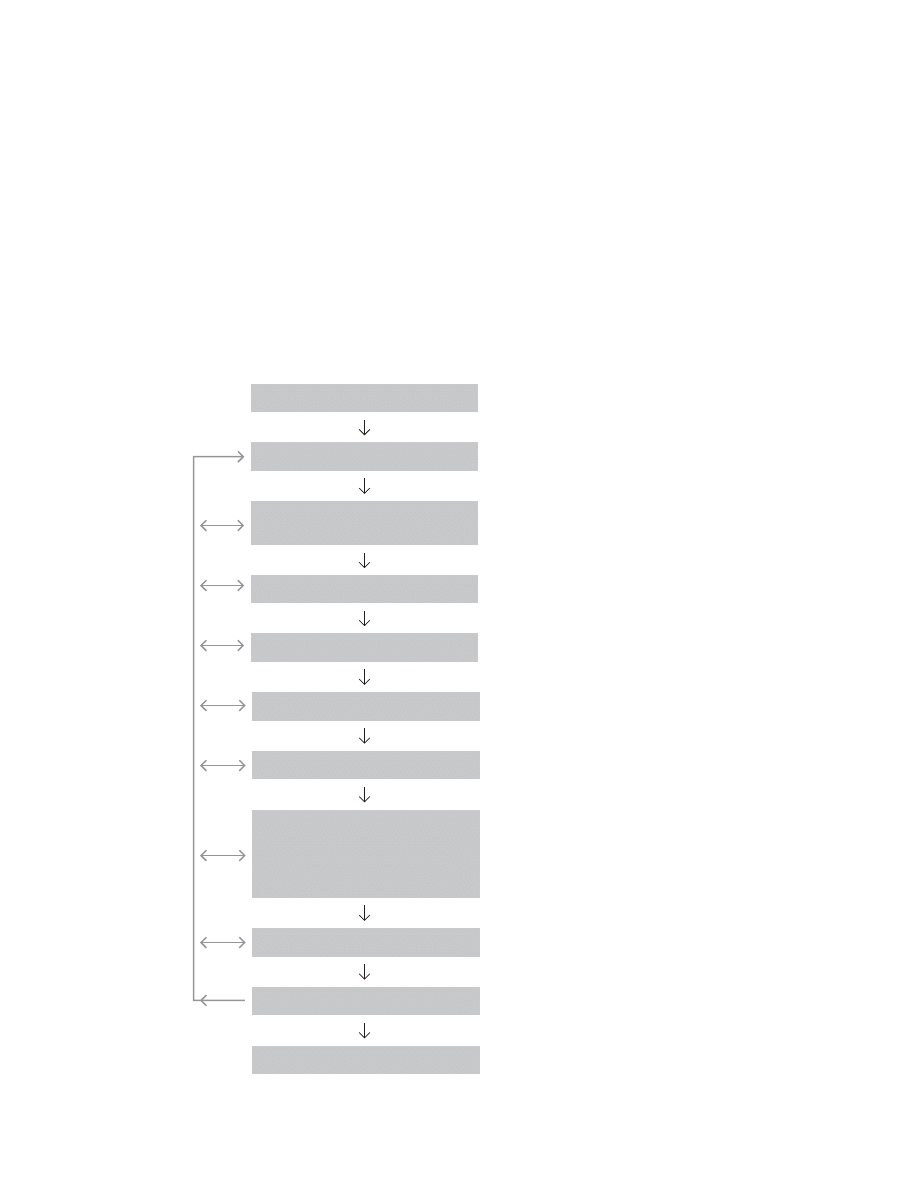
69
0HASES
)TERATIONS
"USINESSMODELING
2EQUIREMENTS
!NALYSISANDDESIGN
)MPLEMENTATION
4EST
$EPLOYMENT
#ONFIGURATIONAND
CHANGEMANAGEMENT
0ROJECTMANAGEMENT
%NVIRONMENT
)NCEPTION
%LABORATION
#ONSTRUCTION
4RANSITION
-AJORMILESTONE
)NTERNALRELEASE
%XTERNALRELEASE
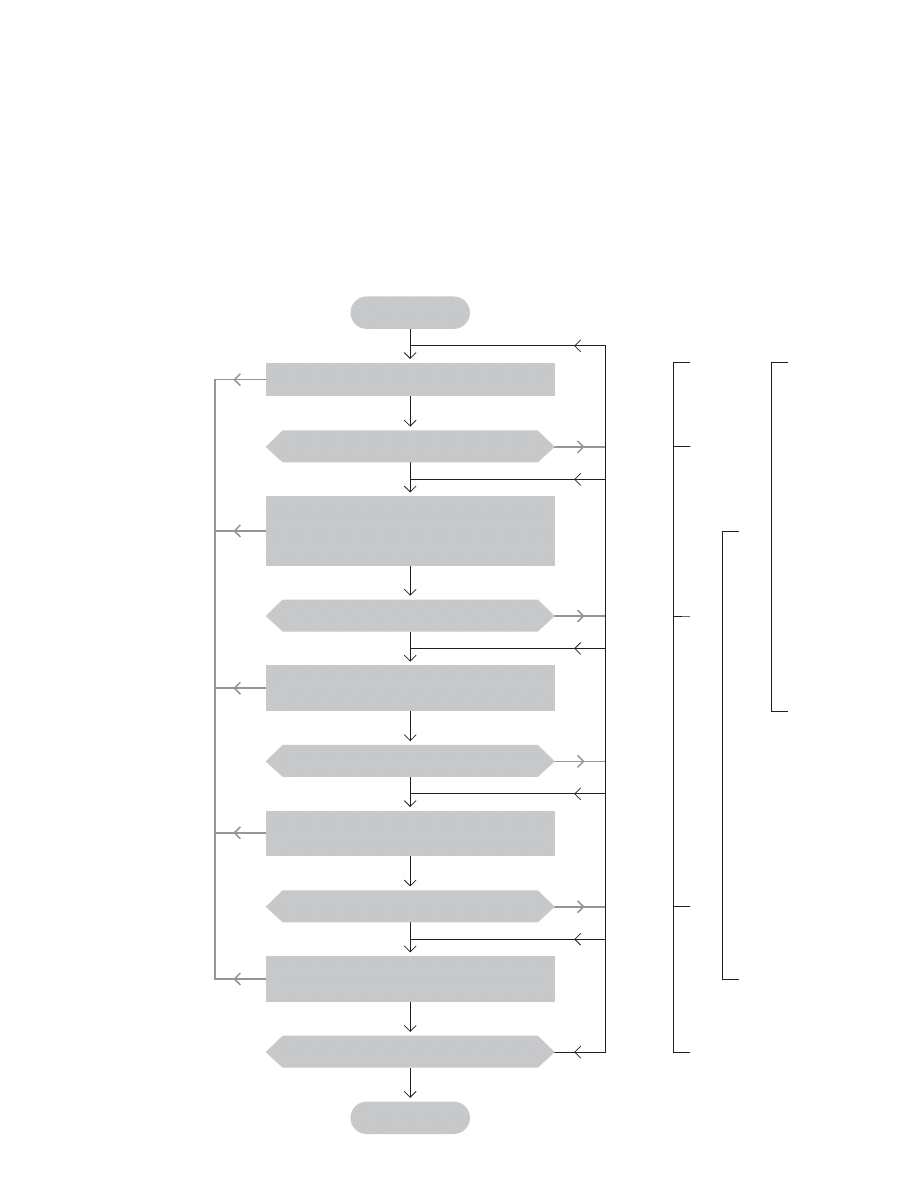
Rational Unifi ed Process (RUP)
after Phillippe Kruchten (2003)
RUP follows an “iterative” lifecycle—as opposed to the “wa-
terfall” lifecycle—“developing in iterations that encompass
the activities of requirements analysis, design, implementa-
tion, integration, and tests. One of the best descriptions is in
Professor Barry Boehm’s paper on the “spiral” model. You
can summarize it with the catch phrase, ‘Analyze a little,
design a little, test a little, and loop back.’” (For more on
Boehm’s model, see page 122.)
Kruchten noted, “The process has two structures or,
if you prefer, two dimensions:
- The horizontal dimension represents time and shows the
lifecycle aspects of the process as it unfolds.
- A vertical dimension represents core process disciplines
(or workfl ows), which logically group software engineering
activities by their nature.”
Rational Software was an independent developer purchased
by IBM in 2003. Rational (and later IBM) developed and
sold a suite of software development tools built around the
Rational Unifi ed Process (RUP). RUP was designed using the
Unifi ed Modeling Language (UML) and has as its underlying
object model, the Unifi ed Software Process Model (USPM).
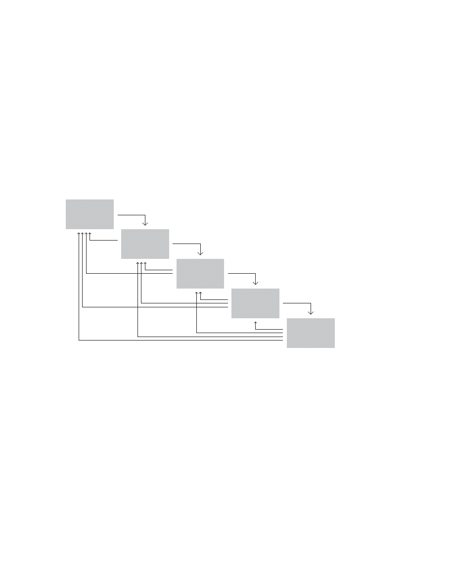
70
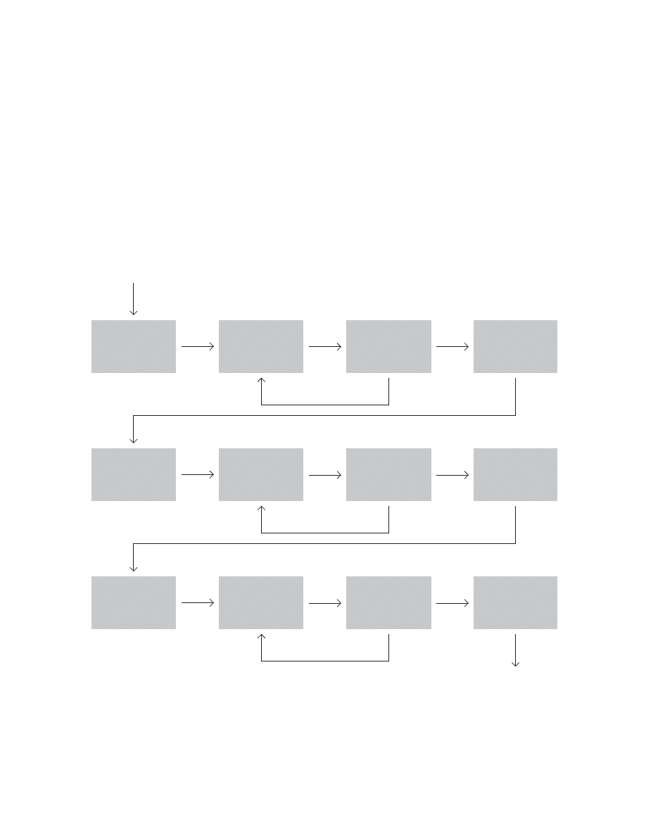
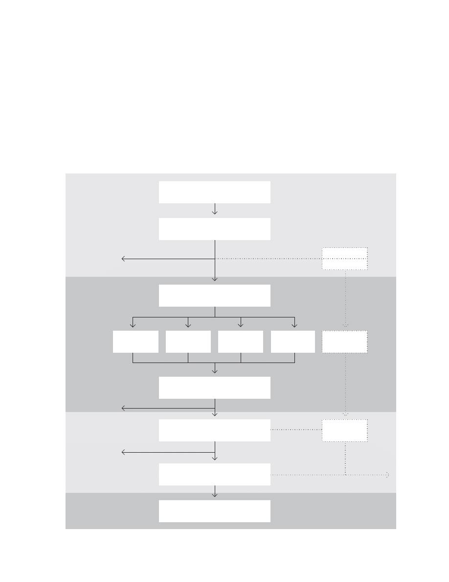
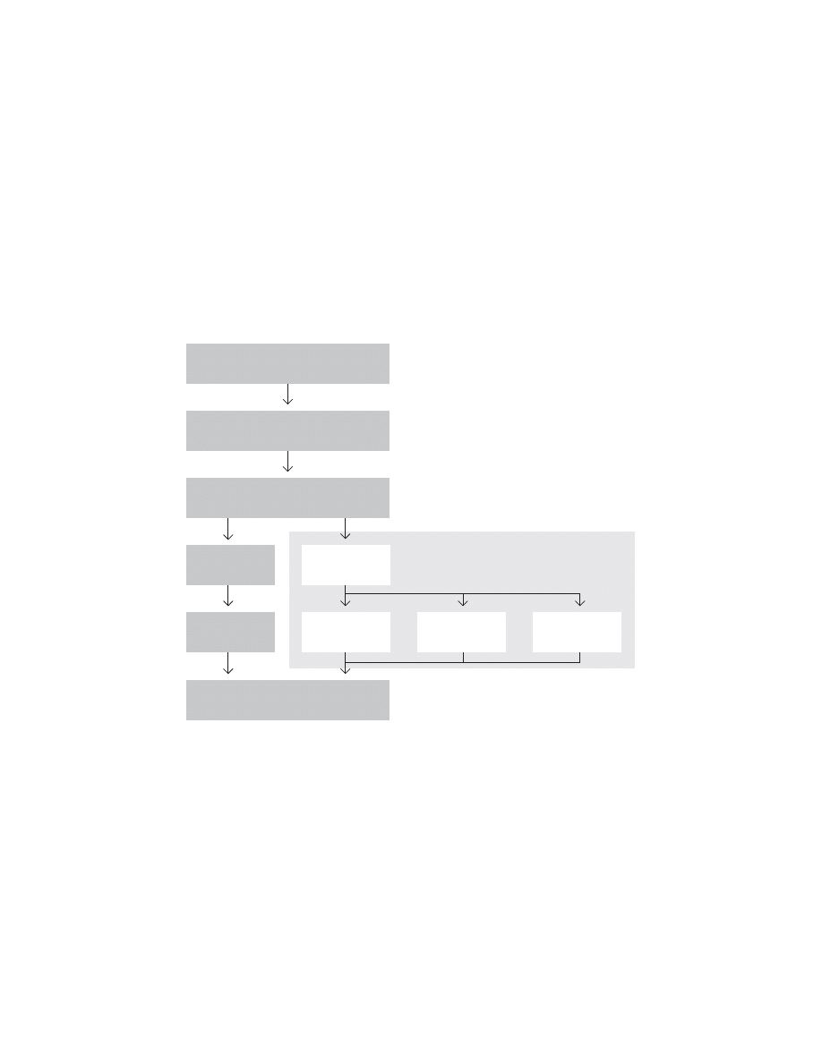
Extreme Programming (XP) Process
after Don Wells (2000)
!RCHITECTURAL
3PIKE
3PIKE
5SER3TORIES
3YSTEM-ETAPHOR
5NCERTAIN
%STIMATES
2ELEASE0LAN
,ATEST6ERSION
"UGS
.EW5SER3TORY
0ROJECT6ELOCITY
4EST3CENARIOS
2EQUIREMENTS
.EXT)TERATION
#USTOMER!PPROVAL
2ELEASE
0LANNING
)TERATION
!CCEPTANCE
4ESTS
3MALL
2ELEASES
#ONFIDENT
%STIMATES
.EXT
)TERATION
2ELEASE
0LAN
0ROJECT6ELOCITY
)TERATION0LAN
.EW&UNTIONALITY
,EARNAND#OMMUNICATE
5NFINISHED4ASKS
5SER3TORIES
$AYBY$AY
)TERATION
0LANNING
"UG&IXES
$EVELOPMENT
,ATEST
6ERSION
"UGS
&AILED!CCEPTANCE4ESTS
.EW5SER3TORY
0ROJECT6ELOCITY
Kent Beck, founder of Extreme Programming, has described
how he created XP in 1996. Chrysler asked him to put a
payroll system project back on track. When they called him,
eighteen months into the project, the system still couldn’t
print a check. Three weeks later, Beck had them print their
fi rst one. “Up until then I believed better programming
would solve all the world’s ills. Yes, you can screw up the
programming so badly you kill the project. Usually, however,
the problem concerns relationships between the business
people and the programmers, the budget process, poor
communications—factors unrelated to the programming.
The context in which the software development takes place
proves as important to the project’s success as the program-
ming itself.”
At its core, XP is a simple process of experimentation and
improvement: Divide a project into “iterations”; in each itera-
tion, implement a few new features called “stories”; for each
story, write “acceptance tests” to demonstrate the story
meets customer expectations. Alan Cooper, however, argues
71
)TERATION
0LAN
.EXT4ASKOR
&AILED
!CCEPTANCE
4ESTS
5NIT4ESTS0ASSED
!CCEPTANCE4EST0ASSED
4ASKS
&AILED!CCEPTANCE4ESTS
3TAND5P
-EETING
5NFINISHED
4ASKS
#OLLECTIVE
#ODE
/WNERSHIP
$AYBY$AY
.EW
&UNCTIONALITY
"UG&IXES
0AIR0ROGRAMMING
2EFACTOR-ERCILESSLY
-OVE0EOPLE!ROUND
#2##ARDS
,EARNAND
#OMMUNICATE
3HARE
4OO-UCH
TO$O
.EXT4ASKOR
&AILED!CCEPTANCE4EST
#2#
#ARDS
0AIR5P
&AILED5NIT4EST
0ASSED5NIT4EST
.EW&UNCTIONALITY
.EW5NIT4ESTS
3IMPLE$ESIGN
#OMPLEX0ROBLEM
2UN!LL
5NIT4ESTS
2UN&AILED
!CCEPTANCE4EST
#REATEA
5NIT4EST
0AIR0RO
GRAMMING
-OVE0EOPLE
!ROUND
2EFACTOR
-ERCILESSLY
!CCEPTANCE
4EST0ASSED
5NIT
4ESTS0ASSED
#ONTINUOUS
)NTEGRATION
7E.EED(ELP
#OMPLEX#ODE
#HANGE0AIR
3IMPLE#ODE
XP is not a design process—because it includes no mecha-
nism for understanding user goals. (For more on Cooper, see
pages 86-91.)
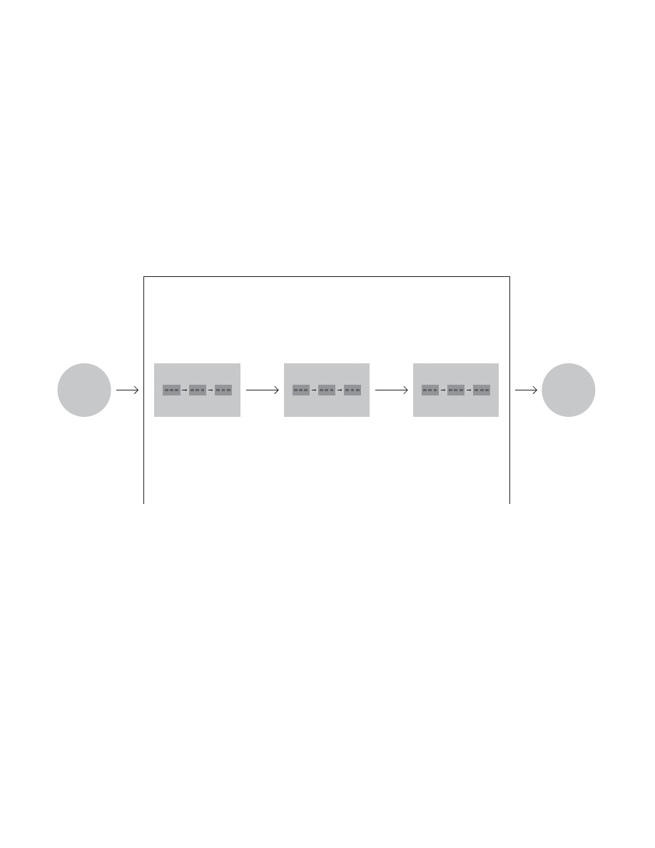
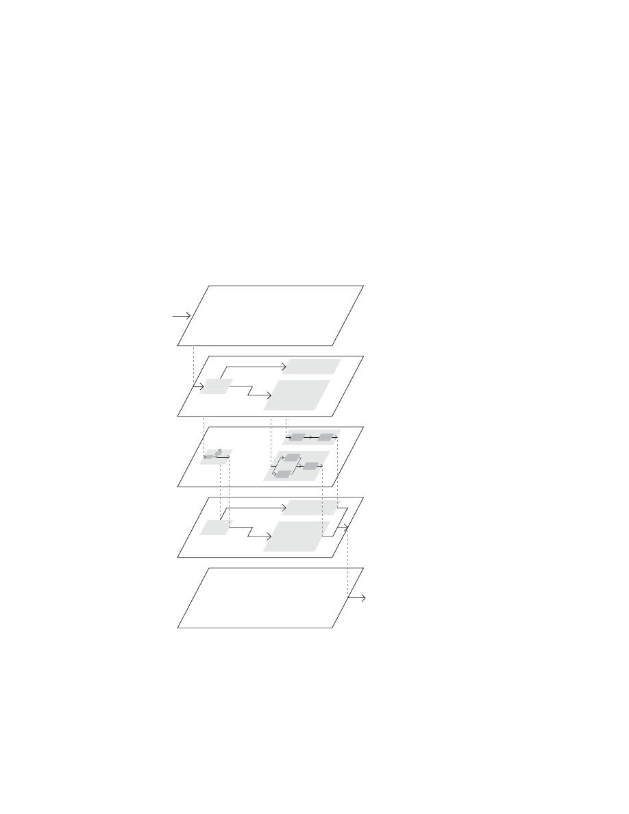
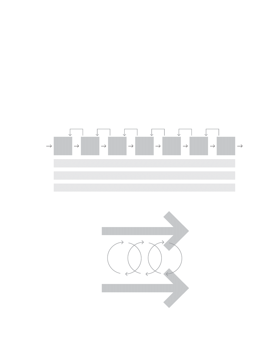
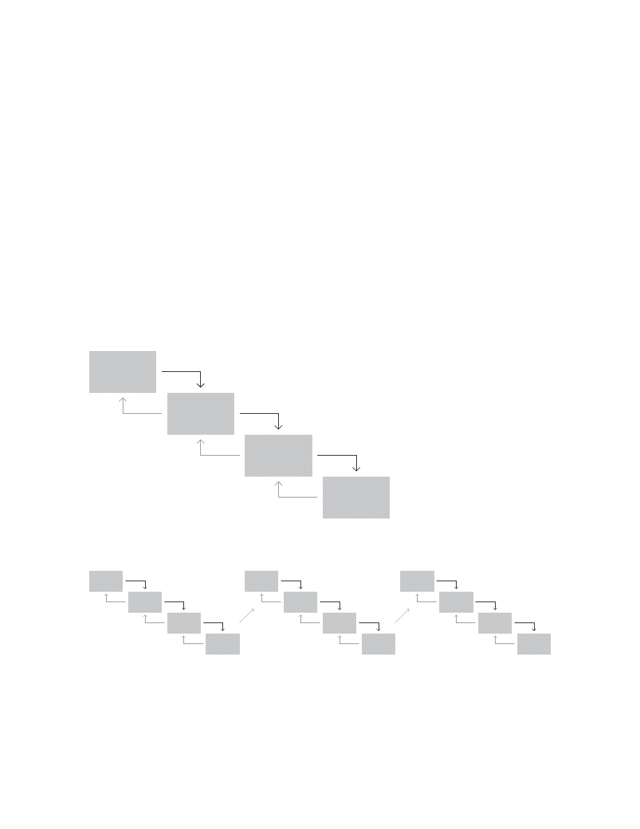
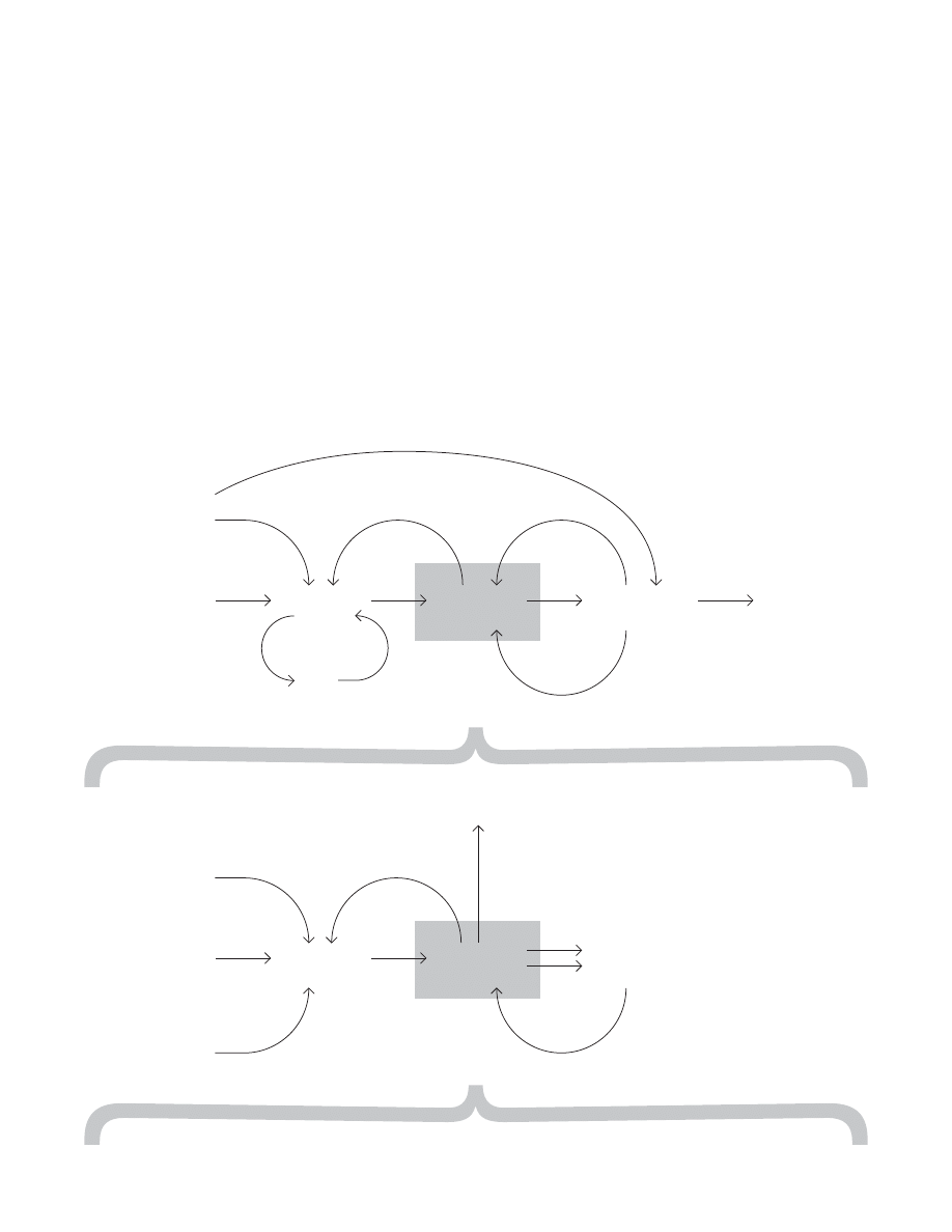
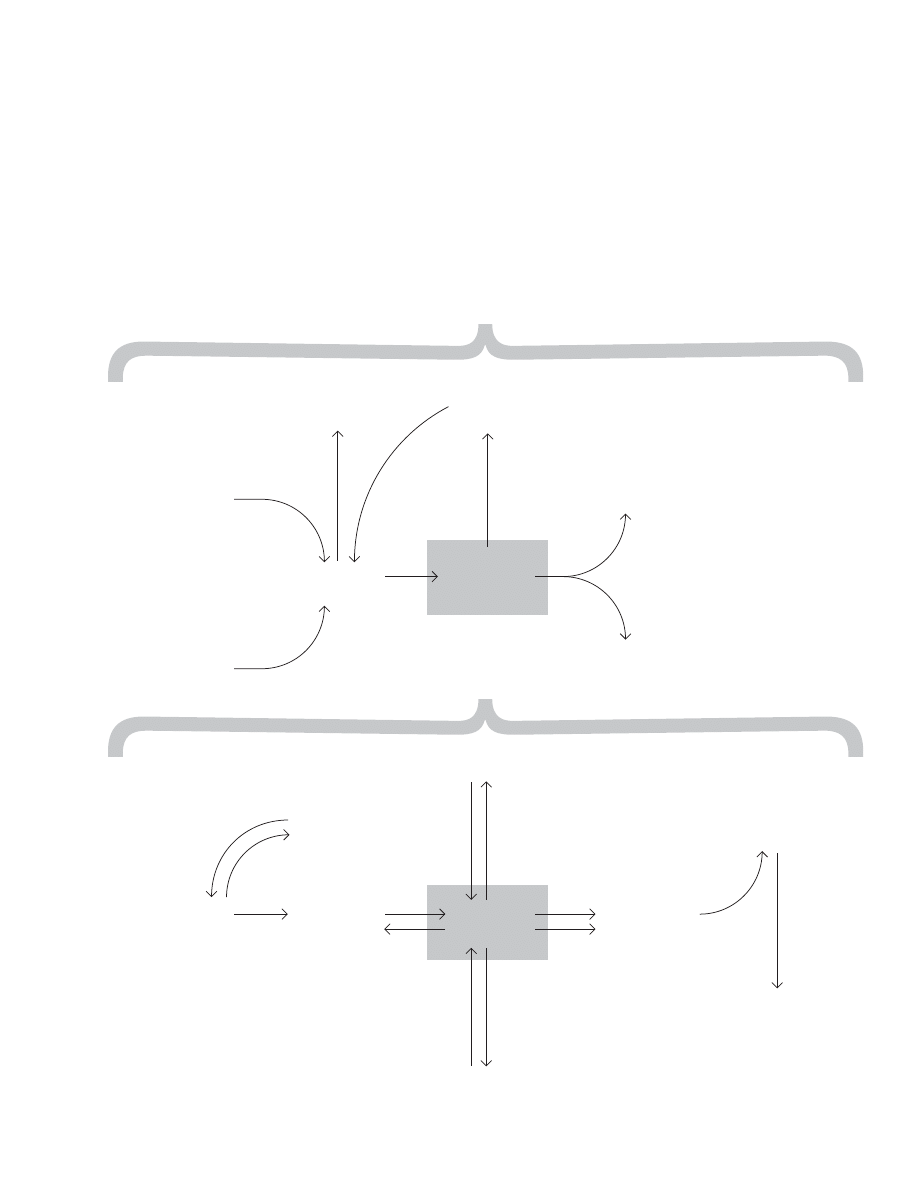
The models below are nested. The fi rst one shows the whole
project; the second “zooms in” on iteration; the third “zooms
in” on development; and the fourth on collective code
ownership. At the center of the last diagram is pair program-
ming, one of the primary distinguishing features of XP. Two
programmers work together at a single computer. Beck
claims this increases quality. It has to be a lot more fun than
coding alone. (For another model of extreme programming,
see page 127.)
72
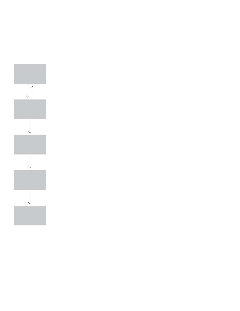
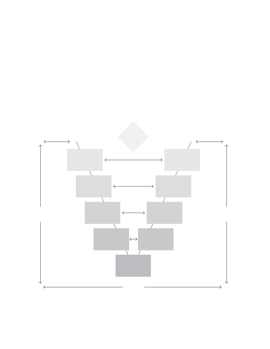
V model
Paul Rock (~1980), IABG (1992)
(IGH,EVEL$ESIGN
)NTEGRATION4ESTING
3OFTWARE
2EQUIREMENTS
3PECIFICATIONS
3YSTEM4ESTING
5SERS3OFTWARE
2EQUIREMENTS
!CCEPTANCE4ESTING
3OFTWARE
$EVELOPMENT
$ETAILED$ESIGN
5NIT4ESTING
#ODING
1UALITY
!SSURANCE
0ROJECT
-ANAGEMENT
#ONTRACT
7ARRANTY
2EVIEW
4EST
The principle characteristic of the V model seems to be that
it weights testing equally with design and development.
Goldsmith and Graham (2002) note, “In fact, the V Model
emerged in reaction to some waterfall models that showed
testing as a single phase following the traditional develop-
ment phases . . . The V Model portrays several distinct test-
ing levels and illustrates how each level addresses a different
stage of the lifecycle. The V shows the typical sequence of
development activities on the left-hand (downhill) side and
the corresponding sequence of test execution activities on
the right-hand (uphill) side”
Accounts of this model’s origin vary. According to Gold-
smith and Graham, “Initially defi ned by the late Paul Rook
in the late 1980s, the V was included in the U.K.’s National
Computing Centre publications in the 1990s with the aim
of improving the effi ciency and effectiveness of software
development.” But according to Morton Hirschberg, formerly
of the Army Research Laboratory, “The V Model is a series
of General Directives (250, 251, and 252) that prescribe or
describe the procedures, methods to be applied, and the
functional requirements for tools to be used in developing
software systems for the German Federal Armed Forces.”
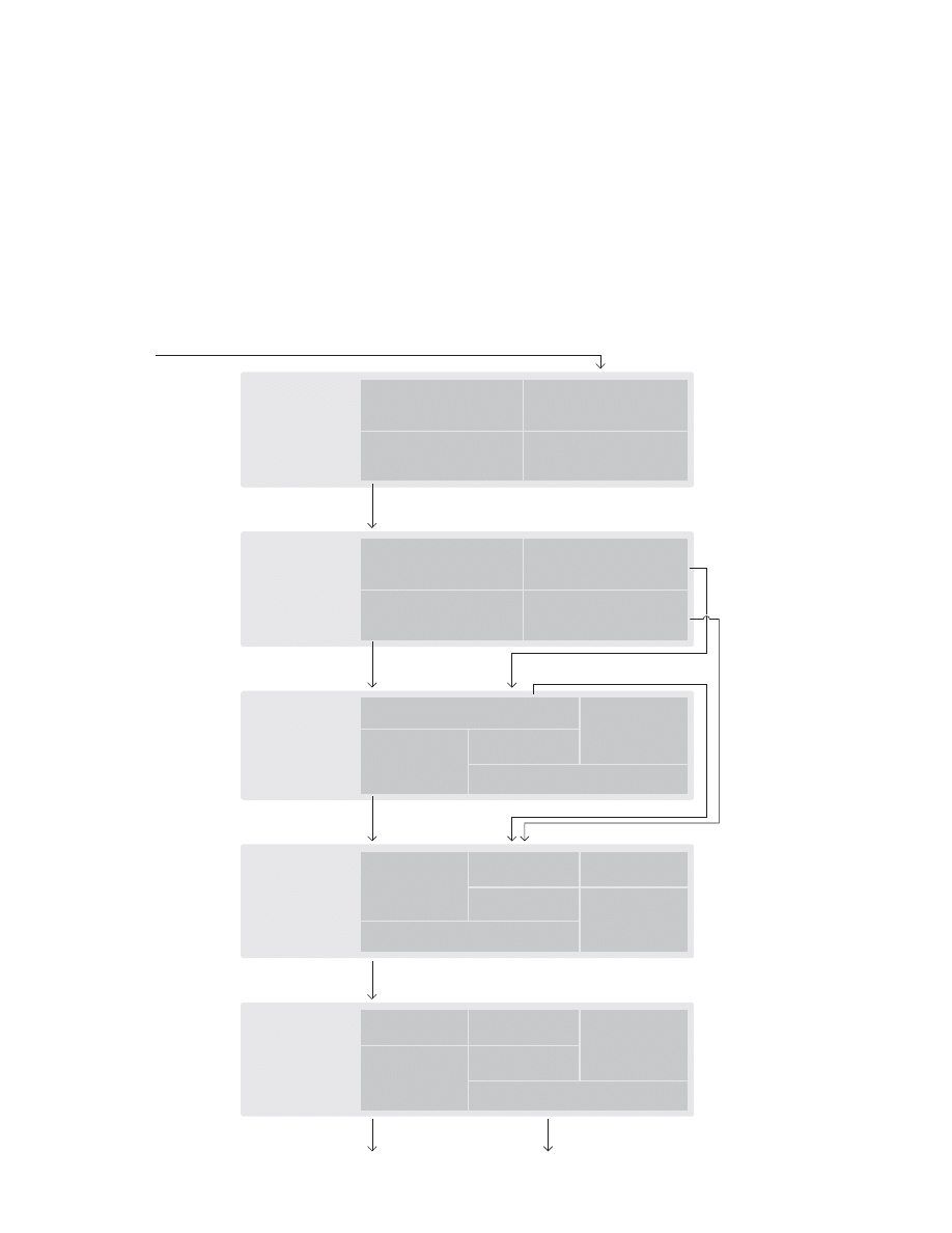
73
0REPERATION
4HE3ESSION
4HE&INAL$OCUMENT
0ROCESS-ODELS
$ATA-ODELS
3CREENS
!SSUMPTIONS
/PEN)SSUES
2EPORTS
0RODUCETHE
&INAL$OCUMENT
!SSEMBLETHE
$OCUMENT
4RACK$ISTRIBUTION
4HE2EVIEW-EETING
!PPROVETHE
$OCUMENT
#HANGING2EQUIREMENTS
4HE7ORKING$OCUMENT
4RAINTHE3CRIBE
6ISUAL!IDS
4HEPRE3ESSION
-EETING
3ET5PTHE-EETING2OOM
)NTERVIEW-ANAGEMENT
0ROJECT2EQUEST
-ANAGEMENT
$EFINITION'UIDE
0RELIMINARY
)NFORMATION
/VERHEADS&LIP#HARTS
AND-AGNETICS
3CRIBE.OTES
AND&ORMS
3IGNED!PPROVAL&ORM
*!$$OCUMENT
7ORKING$OCUMENT
$ATA-ODELSAND
0ROCESS-ODELS
3ESSION
!GENDA
$EFINITION
2ESEARCH
3ELECTTHE*!$4EAM
0REPARETHE-ANAGEMENT
$EFINITION'UIDE
3CHEDULETHE3ESSION
"ECOME&AMILIAR
WITHTHE3YSTEM
#REATE$ATA-ODELSAND
0ROCESS-ODELS
'ATHER0RELIMINARY)NFORMATION
0REPARETHE3ESSION!GENDA
Joint Application Development (JAD)
after Jane Wood and Denise Silver (1995)
JAD sessions (sometimes jam sessions) are intensive work-
shops, usually three to fi ve days long, in which various levels
of users meet with developers to hammer out requirements
for a system. Typically consultants use the process to quickly
lock down user requirements for automation projects—so
they can minimize the time needed to defi ne requirements
and work within a fi xed bid.
According to Carmel et al (1993), “JAD was conceived by
Chuck Moris and Tony Crawford of IBM in 1977. The JAD
approach was loosely derived from another IBM methodol-
ogy—BSP (Business Systems Planning). The fi rst JAD meet-
ings . . . used the same basic JAD concepts still used today:
user participant meetings, magnetic visual displays, and
careful documentations of the meeting.”
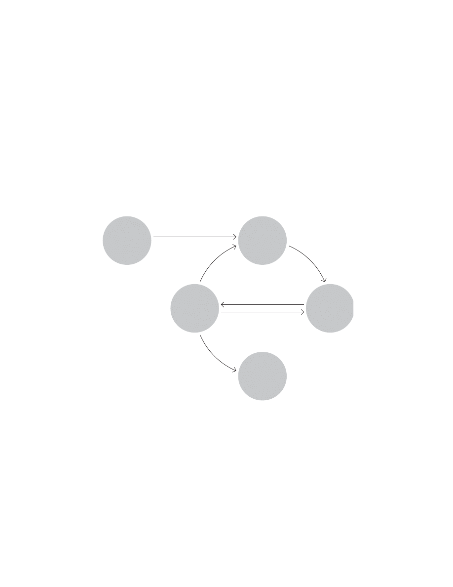
74
ARROWSREPRESENTFLOW
OFINFORMATION
0LANNING
0ROCESSES
#LOSING
0ROCESSES
#ONTROLLING
0ROCESSES
%XECUTING
0ROCESSES
)NITIATING
0ROCESSES
PMBOK (Project Management Body of Knowledge)
PMI (Project Management Institute) (1987)
Charbonneau wrote, “The PMBOK describes a set of gener-
ally accepted practices that PM practitioners can use to
manage all types of projects, including software develop-
ment and deployment projects.
The PMBOK defi nes a project as ‘a temporary endeavor
undertaken to create a unique product or service.’ It defi nes
PM as ‘the application of knowledge, skills, tools, and tech-
niques to project activities to meet project requirements.’
The PMBOK presents [thirty-nine] PM practices in logi-
cal groupings. One dimension describes [nine]‘knowledge
areas’ while the other dimension describes project manage-
ment processes split into fi ve process groups.” The process
groups are shown in the model below.

75
ISO 13407 Human-centered design processes for interactive systems
Tom Stewart et al. (1999)
0LANTHEHUMAN
CENTEREDPROCESS
3PECIFYUSER
ANDORGANIZATIONAL
REQUIREMENTS
0RODUCE
DESIGNSOLUTIONS
5NDERSTANDAND
SPECIFYTHECONTEXT
OFUSE
-EETSREQUIREMENTS
%VALUATE
DESIGNAGAINST
USERREQUIREMENTS
“ISO 13407 provides guidance on achieving quality in use
by incorporating user centered design activities throughout
the life cycle of interactive computer-based systems. It des-
cribes user centered design as a multi-disciplinary activity,
which incorporates human factors and ergonomics knowl-
edge and techniques with the objective of enhancing effec-
tiveness and productivity, improving human working condi-
tions, and counteracting the possible adverse effects of use
on human health, safety and performance.”
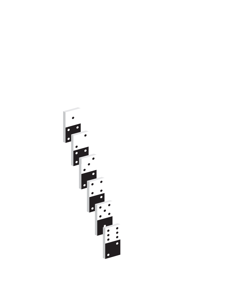
76
7HYDOWETHINKWEWILLUSETHISOFFERING
-ARKETINGDEFINITION
7HATARETHEYLOOKINGFOR
4ASKANALYSIS
7HATELSEISOUTTHERE
#OMPETITIVEEVALUATION
(OWSTHISFORSTARTERS
$ESIGNANDWALKTHROUGH
$OESTHISWORK
7HATWOULDMAKEITBETTER
$ESIGNEVALUATIONANDVALIDATION
(OWDOWESTACKUP
"ENCHMARKASSESSMENT
User-centered design process (UCD)
after Karel Vredenburg (2003)
Vredenburg describes this “simplifi ed generic description of
the design process” as follows: “The design process starts
with the collection of relevant market defi nition information
to answer the basic question, ‘Who do we think will use this
offering?’ This involves understanding the target markets,
types of users, prime competitors, market trends, high level
needs and preferences, and so forth. Next, detailed informa-
tion is collected from representative users within the target
markets to understand their goals and tasks to answer the
question, ‘What are they looking for?’ Following this, we
attempt to understand how the tasks described in the prior
step are carried out today either with a competitor’s product
or an analog method. This answers the question, ‘What else
is out there?’
At this point, conceptual design of the user experience
starts, and early feedback is gathered from users, answering
the question, ‘How’s this for starters?’ This leads to several
cycles of iterative detailed design and user feedback through
design evaluation and validation sessions, answering the
questions, ‘Does this work?’ and ‘What would make it bet-
ter?’ At the end of the development cycle, a user feedback
benchmark assessment session is conducted to answer the
question, ‘How do we stack up?’”
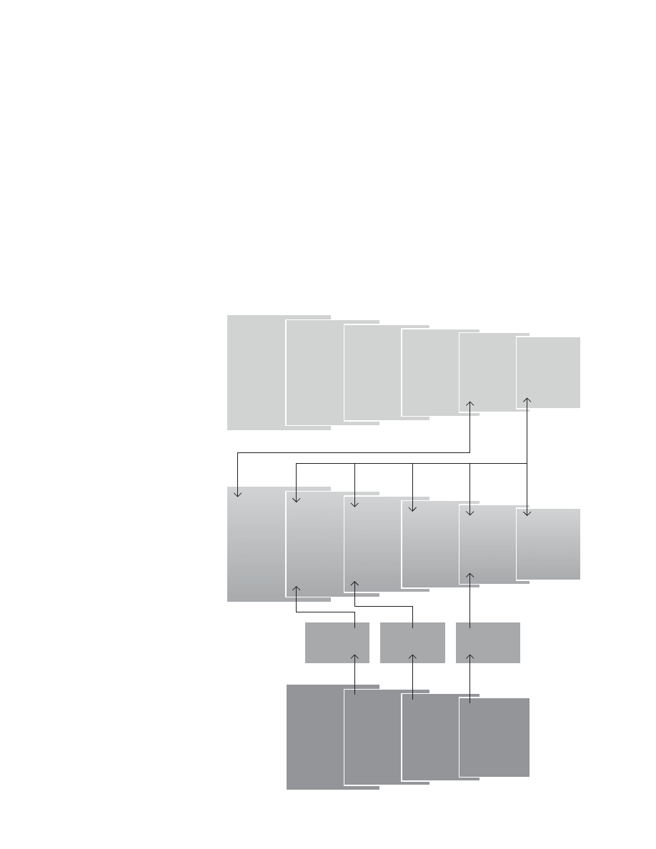
77
Relation of UCD to IPD and Business Management
after Karel Vredenburg (2003)
"USINESS-ANAGEMENT
-ARKETINFORMATION
#USTOMERFEEDBACK
#OMPETITIONINFORMATION
4ECHNOLOGYTOOLS
0RODUCTPORTFOLIO
)NTEGRATED0RODUCT$EVELOPMENT
#ANDIDATEPROJECTS
5SER#ENTERED$ESIGN
5NDERSTAND
THEMARKETPLACE
0ERFORM
MARKET
SEGMENTATION
0ERFORM
PORTFOLIO
ANALYSIS
$EVELOP
MARKETSEGMENT
STRATEGY
ANDPLAN
!LIGN
ANDOPTIMIZE
BUSINESSPLANS
-ANAGE
MARKETSEGMENT
ANDASSESS
PERFORMANCE
3TUDY
ANDDEFINE
USERSTASKSAND
COMPETITION
#REATE
CONCEPTDESIGN
OFUSER
EXPERIENCE
)TERATIVELY
DEVELOPDETAILED
DESIGN
WITHUSERS
6ALIDATE
PRODUCTAGAINST
USEREXPECTATIONS
$EVELOP
PRODUCT
CONCEPTS
$EVELOP
PRODUCT
DEFINITION
ANDPLAN
$EVELOP
ANDVERIFY
1UALIFY
ANDCERTIFY
2AMPUP
ANDLAUNCH
,IFECYCLE
MANAGEMENT
3ATISFIED
CUSTOMERS
#ONCEPT$#0
0LAN$#0
!VAILABILITY$#0
)NTEGRATED0ORTFOLIO-ANAGEMENT4EAM)0-4
0ROJECT$EVELOPMENT4EAMS0$4
The model below illustrates how User Centered Design
(UCD) fi ts into IBM’s integrated product development pro-
cess (IPD) and to its overall business management process.
Vredenburg noted, “Developing a new process and further
enhancing it is only one component, albeit an important one,
in the overall strategy of building ease of use into the total
user experience at IBM. Organizations need to be enabled
to carry out new processes and be provided with leadership
and guidance while executing them.
UCD is a core enabling process in the overall integrated
product development (IPD) process, which is the business
checkpoint mechanism used for all funding and project-
milestone reviews within IBM. Having UCD and UE included
directly in the corporate-wide IPD process ensures that deci-
sions made about an offering will be required to take UCD
and UE information into account.”
Vredenburg also noted creating new corporate-wide posi-
tions, development of education and training, communica-
tions, and collaboration programs, and provision of tools and
technology as part of IBM’s strategy for integrating UCD.

78
0(!3%3
!#4)6)4935--!29
/540543
$EFINE
)DENTIFYTHEPROBLEMOR
PROCESSTOBEFIXEDORTO
BEDESIGNED
-EASURE
)DENTIFYLISTOFCUSTOMER
REQUIREMENTSANDDEVELOP
ANDPRIORITIZE#41SAROUND
CUSTOMEREXPECTATIONS
!NALYZE
#USTOMIZECUSTOMER
EXPECTATIONSTOCREATEA
CLEANPAPERDESIGN
$ESIGN
$EVELOPONECLEANPAPER
DESIGNTOMEETCUSTOMERS
REQUIREMENTS
6ERIFY
)MPLEMENTTHENEW
PROCESSANDVERIFYTHATTHE
DESIGNWORKS
#HARTERAPPROVAL
3UN3HOT7ORKOUT3ESSIONTO
IDENTIFY1UICK(ITS
0HASEAND'ATEAPPROVAL
5PDATEPROJECTIN024
#USTOMER0RIORITIZED.EEDS
)DENTIFYALLCUSTOMERS
0RIORITIZECUSTOMERS
!SSESSCURRENTCUSTOMERDATA
#OLLECTh6OICEOFTHE#USTOMERv
$ETERMINEh6OICEOFTHE#USTOMERv
STRATEGY
!NALYZEANDPRIORITIZENEEDS
#4/$RILLDOWN
$ETERMINECHARACTERISTICSAND
MEASURESFORNEEDS
3ELECTCRITICALFEWMEASURES
-EASUREMENTSYSTEMCAPABILITY
%STABLISHTARGETSANDSPECS
3ETPERFORMANCE3IGMAGOALS
"ENCHMARKINGBESTPRACTICE
IDENTIFIED
0HASEAND'ATEAPPROVAL
5PDATEPROJECTIN024
#ONCEPT$ESIGN
)$FUNCTIONSREQUIREDTOMEET#RITICAL
TO1UALITIES#41S
$EVELOPALTERNATEDESIGNCONCEPTS
3ELECTMOSTPROMISINGCONCEPTS
$EVELOPCONCEPTDESIGN
0ERFORMANCE'AP
$EPLOY#41STOCONCEPTDESIGN
0REDICT#41PERFORMANCE
0ERFORM'!0ANALYSISANDREVISE
CONCEPTDESIGN
0ERFORMDESIGNRISKASSESSMENT
&-%!
2EFINEBENEFITESTIMATES
0HASEAND'ATEAPPROVAL
5PDATEPROJECTIN024
$ETAILED$ESIGN
$EVELOPDETAILEDDESIGNELEMENTS
&LOWDOWN#41STOELEMENTS
%STIMATECAPABILITIESOFDETAILED
DESIGN
0ERFORMDESIGNRISKASSESSMENT
&-%!
!NALYZEGAPANDOPTIMIZEDESIGN
6ERIFICATION0LAN
#USTOMERFEEDBACKONDESIGN
$ETERMINEWHATTOVERIFY
#REATETESTDOCUMENT
#REATEPILOTPLAN
#ONTROL0LAN
)$CRITICALINPUTPROCESSOUTPUT
PARAMETERS
$OCUMENTPROCEDURESTOGUIDE
ONGOINGOPERATION
%XITSTRATEGYIDENTIFIED
!SSESSPATENTABILITYOF
PROCESSPRODUCT
0HASEAND'ATEAPPROVAL
5PDATEPROJECTIN024
6ERIFIED$ESIGN
"UILDPILOTPRODUCTPROCESSFOR
VERIFICATION
%XECUTETESTDOCUMENT
!NALYZERESULTSANDADJUSTDESIGN
0ROJECT#LOSURE
)MPLEMENTDESIGNFULLSCALE
%XECUTECONTROLPLAN
4RANSFEROWNERSHIP
&INANCIALBENEFITSVERIFIEDAND
APPROVED
0HASEAND'ATEAPPROVAL
5PDATEPROJECTIN024
#ELEBRATIONANDRECOGNITION
0ROJECT#HARTER
"USINESS#ASE
0ROBLEM3TATEMENT
'OAL3TATEMENT
3COPE
$EFINITIONOF4EAMAND4IME
#OMMITMENTS
4IMELINE-ILESTONES
%STIMATED"ENEFITS
2ISKSAND#ONSTRAINTS
#HARTER!PPROVALS
(IGH,EVEL0ROCESS-AP
3TAKEHOLDER!NALYSISAND!CTIONS
h6OICEOFTHE#USTOMERv3TRATEGY
0ERFORMANCE3IGMAGOALS
&IRSTPASSSCORECARD
3TAKEHOLDERANALYSISANDACTIONS
!LTERNATEDESIGNCONCEPTS
&INALCONCEPTDESIGN
5PDATEDSCORECARD
3TAKEHOLDERANALYSISANDACTIONS
$ETAILEDDESIGNELEMENTS
4ESTDOCUMENT
0ILOTPLAN
5PDATEDSCORECARD
3TAKEHOLDERANALYSISANDACTIONS
0ILOTPRODUCTPROCESS
5PDATEDSCORECARD
&INALPRODUCTPROCESS
Sun Sigma Framework
DMADV methodology for new products

79
0(!3%3
!#4)6)4935--!29
/540543
$EFINE
)DENTIFYTHEPROBLEMAND
IDENTIFYTOPTO#RITICAL
TO1UALITIES#41STO
FOCUSIMPROVEMENTSON
-EASURE
-EASURETHECURRENT
PERFORMANCEOFTHEDEFECT
#41NOTMETANDDISPLAY
VARIATIONINTHEPROCESS
!NALYZE
!NALYZETHEPROCESS
VARIATIONTODETERMINEROOT
CAUSESANDOPPORTUNITIES
FORREDUCINGTHEVARIATION
)MPROVE
'ENERATESELECTDESIGN
TESTANDIMPLEMENT
IMPROVEMENTS
#ONTROL
)NSTITUTIONALIZETHE
IMPROVEMENTAND
IMPLEMENTONGOING
MONITORING
#HARTERAPPROVAL
3UN3HOT7ORKOUT3ESSIONTO
IDENTIFY1UICK(ITS
0HASEAND'ATEAPPROVAL
5PDATEPROJECTIN024
/UTPUT-EASUREMENT
0ROJECT9ANDDEFECTDEFINED
0ERFORMANCESPECIFICATIONFOR9
$ATACOLLECTIONPLAN
-EASUREMENTSYSTEMVALIDATED
#OLLECTDATAFOR9
0ROCESSCAPABILITYFOR9
)MPROVEMENTGOALFOR9
"ENCHMARKINGBESTPRACTICE
IDENTIFIED
0HASEANDGATEAPPROVAL
5PDATEPROJECTIN024
2OOT#AUSE!NALYSIS
"RAINSTORMALLPOSSIBLE8S
0RIORITIZELISTOF8S
6ERIFY8WITHDATA
0ERFORMANCE'AP
)DENTIFYGAPSBETWEENCAPABILITIES
ANDCUSTOMERREQUIREMENTS
2EEVALUATE$-!)#VS$-!$6
"ENCHMARKING
2EFINEBENEFITESTIMATES
0HASEAND'ATEAPPROVAL
5PDATEPROJECTIN024
3OLUTION'ENERATIONAND0ILOT4EST
$EVELOPANDSELECTSOLUTIONS
0ERFORMPILOTOFSOLUTIONS
#ONFIRMIMPROVEMENTS
#ONFIRMPRIORITIZED8S
-APNEWPROCESS
$ETERMINENEWCAPABILITY
PERFORMANCE
)MPLEMENTATION0LAN
$EVELOPIMPLEMENTATIONPLAN
)DENTIFYCONTROLS
)MPLEMENTIMPROVEMENTS
"ENCHMARKING
0HASEAND'ATEAPPROVAL
5PDATEPROJECTIN024
3USTAINED3OLUTION
0ROCESSDOCUMENTATIONCONTROLSIN
PLACE
-EASUREPERFORMANCE
#ONFIRMSUSTAINABLESOLUTION
6ALIDATEMEASUREMENTSYSTEMON8S
0ROJECT#LOSURE
%VALUATIONTRANSITIONOPPORTUNITIES
)DENTIFYOTHERIMPROVEMENT
OPPORTUNITIES
0ROJECTDOCUMENTATIONCOMPLETE
4RANSLATIONPACKAGE
&INANCIALBENEFITSVERIFIEDAND
APPROVED
0HASEAND'ATEAPPROVAL
5PDATEPROJECTIN024
#ELEBRATIONANDRECOGNITION
0ROJECT#HARTER
"USINESS#ASE
0ROBLEM3TATEMENT
'OAL3TATEMENT
6ALIDATEDCUSTOMER#41S
3COPE
$EFINITIONOFTEAMANDTIME
COMMITMENTS
4IMELINEMILESTONES
%STIMATEDBENEFITS
2ISKSANDCONSTRAINTS
#HARTERAPPROVAL
(IGH,EVEL0ROCESS-AP
3TAKEHOLDER!NALYSISAND!CTIONS
$ETAILEDPROCESSMAP
3TAKEHOLDERANALYSISANDACTIONS
3TAKEHOLDERANALYSISANDACTIONS
0OSSIBLESOLUTIONS
0ILOTOFSOLUTIONS
-APOFNEWPROCESS
)MPLEMENTATIONPLAN
&INALIMPROVEMENTS
3TAKEHOLDERANALYSISANDACTIONS
0ROJECTDOCUMENTATION
4RANSLATIONPACKAGE
Sun Sigma Framework
DMAIC methodology for improving existing products

80
0(!3%3
!#4)6)4935--!29
/540543
#ONCEPT
0LAN
$EVELOP
)NTEGRATE
4EST
3YSTEM4EST
#USTOMER
!CCEPTANCE
$EPLOY
3USTAIN
2ETIRE
"USINESS5NITCREATES
A0RODUCT0ORTFOLIO
3TEERING#OMMITTEE
#REATEOPTIONAL
3UB3TEERING
#OMMITTEES
#REATEOPTIONAL
#ONSOLIDATION4EAMS
#4EAMS
)NFLUENCE,INE
-ANAGEMENTTOSTART
PROJECTS
!PPROVEEACH
#OMPONENT0ROJECT
0LAN
!PPROVEEACH
#OMPONENT0ROJECT
!RCHITECTURE
4ESTEACHCOMPONENT
$ELIVEREACH
#OMPONENT0ROJECTTO
#4EAM
#ONDUCT#OMPONENT
4/)
4EST#OMPONENTS
#ONDUCT0RODUCT4/)
%XECUTE3YSTEM4EST
#REATETRAINING
MATERIALS
#REATEANNOUNCEMENT
PACKAGE
6ERIFYEXECUTION
THROUGHSYSTEMTEST
OF0RODUCT0LAN
%XECUTE#USTOMER
!CCEPTANCE4EST
!NNOUNCETOINTERNAL
COMMUNITY
!NNOUNCETOCHANNELS
#REATETRAINING
MATERIALS
#ONDUCT2EVENUE
2ELEASE
!NNOUNCETOTHE
PUBLIC
#REATEANDDELIVER
0RODUCTION4RAINING
#REATEANDEXECUTE
,AUNCH0ACKAGE
#ONDUCTSTLESSONS
LEARNEDREVIEW
3USTAINTHEPRODUCT
#ONDUCTONGOING
VIABILITYASSESSMENTS
!NNOUNCEINTENTTO
ENDOFLIFE
#ONDUCTNDLESSONS
LEARNEDREVIEW
)NVENTORYCAP
EQUIPMENTAND
DISPOSABLES
!NNOUNCEENDOFLIFE
TOPUBLIC
%XECUTE%NDOF
0RODUCT0LAN
#ONDUCTRDFINAL
LESSONSLEARNED
REVIEW
0RODUCT
2EQUIREMENTS
$OCUMENT
)NITIAL&UNCTIONAL
3PECIFICATION
0RODUCT#ONTENT
$OCUMENT
&UNCTIONAL
3PECIFICATION
0RODUCT0LAN
$OCUMENT
)NITIAL0RODUCT
#ONTENTS,IST"/-
PAGERSFORREQUIRED
COMPONENTS
#OMPONENT0LANS
)NTERNAL$ESIGN
3PECIFICATION
#OMPONENT
)NTEGRATION4EST0LANS
PAGERSFOR
COMPONENTS
&INALIZED00$
/PS-RG0LAN
&INALIZED3ALES0LAN
3YSTEM4EST2EPORTS
5PDATED0RODUCT
"OUNDARY3UMMARY
!PPROVED0RODUCT
#ONTENT,IST"/-
$EFECT2ESOLUTIONAND
2ISK!SSESSMENT
2EPORTS
&INALIZED00$
-ARKETING0LAN
4RAINING-ATERIALS
!NNOUNCEMENT
0ACKAGE
&INALIZED3UPPORT
0LAN
#USTOMER
!CCEPTANCE4EST
2EPORT
$EFECT2ESOLUTIONAND
2ISK!SSESSMENT
2EPORTS
4RAINING-ATERIALS
%NDOF0RODUCT0LAN
&INALIZED%NDOF
3UPPORT,IFE0LAN
Sun Product Lifecycle (PLC)
Sun Software Development Framework (SDF)
“Mapped” processes for product instances

81
0(!3%3
!#4)6)4935--!29
/540543
#ONCEPT
0LAN
$EVELOP
)NTEGRATE
4EST
3YSTEM4EST
#USTOMER
!CCEPTANCE
$EPLOY
3USTAIN
2ETIRE
"5CREATES0RODUCT
,INE0ORTFOLIO3TEERING
#OMMITTEE0#
$EVELOPTHEPRODUCT
ANDVERIFYCOMPONENT
PERFORMANCE
$EVELOP3UNSAND
CRITICALPARTNERS
PRODUCTIONPROCESSES
0REPARE
COMPREHENSIVEPLANS
FORINTRODUCTIONAND
SUPPORT
1UALIFYTHEPRODUCT
FUNCTIONALITYAND
PERFORMANCE
1UALIFYPRODUCTION
ANDSUPPLIER
PROCESSES
#ONFIRMPRODUCT
FUNCTIONALITYIN
PLANNEDCUSTOMER
ENVIRONMENTS
%XECUTEINTRODUCTION
ANDSUPPORTPLANS
,AUNCHTHEPRODUCT
3TABILIZEOPERATIONAL
ANDSUPPORT
PROCESSES
-ANAGEPRODUCT
PROFITABILITYAND
GROWTH
0ROVIDECUSTOMER
SUPPORTANDDEFECT
TRACKING
2ETIREPRODUCTAND
MANAGECUSTOMER
TRANSITIONS
0RODUCT,INE
2EQUIREMENTS
$OCUMENT
)NITIAL&UNCTIONAL
3PECIFICATION
0RODUCT,INE#ONTENT
$OCUMENT
&UNCTIONAL
3PECIFICATION
0RODUCT,INE0LAN
$OCUMENT
Sun Product Lifecycle (PLC)
Sun Software Development Framework (SDF)
“Mapped” processes for product lines

Complex linear
models
Most of models of the design process
have three to seven steps.
If they contain more steps,
they’re typically organized into a tree
with three to seven major steps.
This may be another function
of George Miller’s famous “Magic Number 7.”
The next section includes
some very detailed models.
82

83
Vanguard Group
The model on the following spread comes from the design
team at the Vanguard Group. So far as I know, they have not
published it.

84
Web development process
after Vanguard Group (circa 1999)
0(!3%30LANNING
!#4)6)4935--!29
/540543
6!,5%!$$WITHLESSONSLEARNED
#REATE"USINESS
#ASEAND)NITIAL
3COPE
#OMPLETE)NITIAL
5SER2ESEARCH
#REATE3ITE
!RCHITECTUREAND
#ONCEPTUAL
$ESIGN
"EGIN
&UNCTIONAL
2EQUIREMENTS
#REATE
.AVIGATIONAL
$IAGRAMS
#OMPLETE
#ONCEPTUAL
4ESTING
#REATE$ETAILED
7IREFRAMES
)DEA
#ONDUCTUSER
RESEARCH
$EVELOPBUSINESS
CASESUMMARY
#ONDUCTCOMPETITIVE
ANALYSIS
$EFINEGOALSAND
OBJECTIVES
$EVELOPUSER
RESEARCHPLAN
#REATEUSERPROFILES
"EGINTASKANALYSIS
"EGINTOESTABLISH
MENTALMODEL
2EFINEPROFILE
MAPPINGTOSEGMENT
STRATEGY
2EFINETASKANALYSIS
2EFINEMENTALMODEL
#REATEOUTLINEOF
CONTAINERSANDTHEIR
RELATIONSHIPS
"EGINTOhTHUMBNAILv
HIGHLEVELLOOKAND
FEEL
6ALIDATIONOFCONCEPTS
WITHTHEBUSINESS
(EAVYITERATIONOF
REQUIREMENTS
ARCHITECTUREAND
DESIGN
"UILDARCHITECTURE
FROMCONTAINER
RELATIONSHIPOUTLINE
ANDMENTALMODELS
)DENTIFYDETAILED
CONTENTINVENTORY
-APDETAILEDCONTENT
TOARCHITECTURE
#ONDUCTGAPANALYSIS
)DENTIFYANDPRIORITIZE
KEYCONTENT
)DENTIFYTOPTASKSFOR
TESTING
6ALIDATEREQUIREMENTS
ANDARCHITECTUREWITH
USERS
0REPAREAPPROPRIATE
MATERIALSFORTEST
#ONDUCTTESTS
#REATERECOMMENDA
TIONSBASEDON
FINDINGS
#REATEhVISUALIZATIONv
OFREQUIREMENTS
!UDITPAGESTO
UNCOVERFUNCTIONAL
ANDNONFUNCTIONAL
REQUIREMENTS
"EGINTOREFINE
APPLYDESIGN
STANDARDS
-AJORREVIEWPOINT
4EAMMUSTRECEIVE3ENIOR-ANAGEMENT
APPROVALTOPROCEED
"USINESSCASE
#LIENT)NTERVIEWS
2EPORTOFFINDINGS
3ITEARCHITECTURE
DESIGNCONCEPTS
2EQUIREMENTS
.AVIGATIONAL
DIAGRAMS
0APERMOCKUPS
5SABILITYREPORT
7IREFRAMESITERATED
3EPARATEUSERGOALS
BUSINESSSTRATEGY
ANDTHENRECONCILE
DISCREPANCIES
)NVOLVETHERIGHT
PEOPLEEARLYINTHE
PLANNINGPROCESS
7EBTEAM
PARTICIPATIONAT
BRAINSTORMING
STAGEAND
DURINGSTRATEGY
FORMULATION
#ONTROLCOMPLEXITY
5NDERSTANDUSER
GOALSANDBEHAVIORS
TOAVOIDLOWUSAGE
#OHESIVETEAM
ENVIRONMENTCREATES
EFFICIENTINFORMED
OUTPUTANDRAPID
ITERATION
'AINBUSINESSBUYIN
BEFOREENTERINGINTO
COSTLYDESIGN
DEVELOPMENTCYCLE
2EDUCESCOMPLEXITY
TASKSLANGUAGE
METAPHORSETC
#REATESCLARITYAROUND
TASKSFOCUSESTHE
EFFORT
!SSISTSWITHBUSINESS
PRIORITIZATIONREAL
ESTATE
(IGHLEVELTECHNOLOGY
ASSESSMENT
"ALANCEBUSINESS
OBJECTIVESANDUSER
NEEDSEXPECTATIONS
!SSESDESIGN
STANDARDSAND
DETERMINEIF
DIFFERENTIATIONIS
NECESSARYANDWHY
4RANSLATIONOF
COMPETITIVEANALYSIS
TOCONCEPT
+EEP)MPORTANTTASKS
WITHINAFEWCLICKS
-APARCHITECTURE
BACKTOBUSINESS
STRATEGYANDUSER
GOALS
#ONSIDERUSAGE
REPORTING
#LARIFYSCOPEAND
FUNCTIONALITY
#ONSIDERCROSSOVER
EXPERIENCE
5SABILITYEXPERTISE
ALLOWSFORRAPID
VALIDATION
ADJUSTMENTOF
ARCHITECTURE
REQUIREMENTS
"USINESSANALYSISOF
TESTRECOMMENDA
TIONS
*UDGEMENTIN
APPLYINGTHERIGHT
USABILITYTECHNIQUES
TOTHEPROJECT
%NSURETHATDESIGNIS
SCALEABLEANDFLEXIBLE
TOALLOWFORONGOING
MAINTENANCE
!LLOWBUSINESSTOSEE
ANDPARTICIPATEINTHE
EVOLUTIONOFTHESITE
#ONSIDERERROR
CONDITIONS
!DDITIONALDESIGN
STRATEGYSTANDARDS
ANALYSIS
2EQUIREMENTS#ONCEPTUAL$ESIGN
!NALYSIS$ESIGN
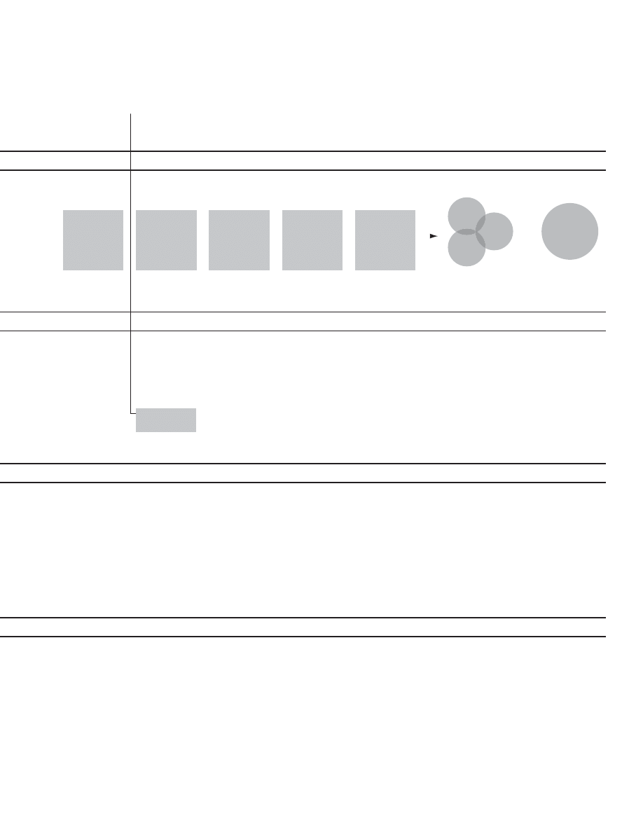
85
#OMPLETE5SER
4ESTINGOF
7IREFRAMES
#REATE$ESIGN
3TRATEGY
$ESIGN
'UIDELINE
3PECIFICATION
#OMPLETE5SER
)NTERFACE
#OMPLETE
4ESTINGOF&INAL
5SER)NTERFACE
$ELIVER5)
3PECIFICATIONS
AND2ELATED
$OCUMENTATION
0REPARENEXTLEVELOF
TASKSANDTEST
MATERIALS
#ONDUCTTEST
2EPORTUSABILITYTEST
FINDINGS
)NTERPRETFINDINGSAND
MAKERECOMMENDA
TIONS
!SSEMBLETHEDESIGN
STRATEGYAND
DOCUMENT
2EFINEANDAPPLYSITE
SPECIFICDESIGN
GUIDELINES
)DENTIFYKEYCONTENT
PLACE
6ALIDATEDESIGN
STRATEGYWITHTHE
BUSINESS
-AJORREVIEWPOINT
4EAMMUSTRECEIVE3ENIOR-ANAGEMENT
APPROVALTOPROCEED
#REATEDETAILED
DESIGNFORALLUNIQUE
INSTANCES
#ONDUCTFINALTESTING
TOUNCOVERMAJOR
FLAWS
&OCUSTESTINGON
UNIQUEINSTANCES
#REATERECOMMENDA
TIONSBASEDON
FINDINGS
&INALIZE5)
SPECIFICATIONS
PROTOTYPEOFUNIQUE
INSTANCES
$ELIVERANDREVIEW5)
WITHTHEDEVELOPMENT
TEAM
'ATHERDATA
5NCOVERISSUESAND
DEFECTS
5SE$-!)#TOIDENTIFY
IMPROVEMENTS
7ORKWITHBUSINESSTO
SUBMIT3#2SAND
PROJECTREQUESTS
&OLLOW3$,#THROUGH
TOELEVATION
-ONITOR
IMPROVEMENTS
THROUGHDATA
5SABILITYREPORT
$ESIGNSTRATEGY
h3KINNEDPROTOTYPEv
h3KINNEDPROTOTYPEv
ITERATED
5SABILITYREPORT
0ROTOTYPE
DOCUMENTATION
$ATETRACKINGAN
ANALYSIS
6/#0ARETOS
7EB5SAGE2EPORTS
%RROR,OGS
%XIT3URVEYS
74334RENDS
.)#%CALLS
0REDICTUSERINTEREST
)NCORPORATINGMULTIPLE
OPTIONSINTOTESTSTO
REDUCECOMPLEXITYFOR
THEUSER
"USINESSANALYSISOF
TESTRECOMMENDA
TIONS
)MPLEMENTADHERETO
CHANGECONTROL
PROCESS
,OOKFORCOMPATIBILITY
ACROSSBROWSERS/3
ANDDOWNLOADSETC
,OOKANDFEELOFTHE
SITEISBEING
ESTABLISHEDAND
VALIDATEDWITHKEY
BUSINESS
STAKEHOLDERS
%VALUATIONOFPAGE
LOADS
-ANAGEBUSINESS
FEEDBACKBYAREAOF
EXPERTISEAVOID
DESIGNBECOMINGTHE
FOCUSVERSUSCONTENT
(IGHDEGREEOFDESIGN
BUSINESSITERATION
#REATEASITETHAT
hHANGSTOGETHERv
#OVERINGALL
POSSIBILITIESTHROUGH
UNIQUEINSTANCES
&INALCHECKPOINTWITH
USERSTOVALIDATETHE
EXPERIENCEDESIGN
ARCHITECTURECONTENT
ANDUSABILITY
&INALIZETEMPLATEFOR
USAGEREPORTING
#ONTINUAL
IMPROVEMENTOF
DOCUMENTATIONTO
CREATEEFFICIENCIES
BETWEENDESIGNAND
DEVELOPMENT
4HOROUGHATTENTIONTO
INTEGRATIONTEST
1UALITYANDCONTROL
ASSESSMENTBY
DESIGNTEAMINTHE
INTEGRATIONREGION
0AGEPERFORMANCE
ANALYSISAND
TROUBLESHOOTING
$ETAILEDANALYSISOFALL
DATA0#%6/#
7527)3306#3
4RACKER2ESEARCH
ETC
6/#ANALYSIS
65%PROJECTS
0RIORITIZATIONOF
ENHANCEMENTSWITH
THEBUSINESS
"UILD
4EST
%LEVATE
#ONTINUOUS
)MPROVEMENT
2EFINEMENTOF5)$ESIGN
"UILD-ONITOR)MPROVE

86
Alan Cooper
Few people are good computer programmers and also good
interaction designers. Alan Cooper is one. Cooper’s favorite
topic is what’s wrong with the software that increasingly fi lls
our lives and how it came to be so bad. He holds forth on
the subject in two books, About Face: The Essentials of User
Interface Design (1995) and The Inmates Are Running the
Asylum: Why High-Tech Products Drive Us Crazy and How to
Restore the Sanity (1999).
In summary, Cooper’s argument is as follows: In software,
the cost of adding one more new feature is almost nothing;
no additional material or manufacturing costs restrain feature
creep. The trouble is: Each additional feature makes the
product more complicated to understand and more diffi cult
to use.
In the traditional software development process, many
people inside a company—and oftentimes customers as
well—ask for features. Thus, a list of features often becomes
the de facto product plan. Programmers make this approach
worse by picking or negotiating their way through the list,
often trading features for time. In such a process, Cooper
points out, it’s hard to know when a product is complete.
Cooper advocates fi ve signifi cant changes to conventional
methods of software development in his goal-directed de-
sign process:
1) Design fi rst, program second.
2) Separate responsibility for design from responsibility
for programming.
3) Hold designers responsible for product quality and
user satisfaction.
4) Invent on specifi c user for your product—a persona.
Give that user a name and an environment and derive
his or her goals.
5) Work in teams of two: designer and design communicator
I developed the diagrams that follow based on a series of
conversations with Cooper and members of his staff, includ-
ing Dave Cronin, David Fore, Kim Goodwin, Jonathan Kor-
man, and Robert Reimann. The fi rst two were fi rst published
in the AIGA journal, Gain. The second two have not been
published previously.

87
3HIP
#ODE
$ESIGN
)NITIATE
3HIP
-ANAGERS
$ESIGNERS
0ROGRAMMERS
1!
#ODE
)NITIATE
"UG4EST
$ESIGN
5SER4EST
3HIP
-ANAGERS
0ROGRAMMERS
1!
$ESIGNERS
5SABILITY&OLKS
#ODE
)NITIATE
4EST
3HIP
-ANAGERS
0ROGRAMMERS
1!
"UG4EST
5SER4EST
5SABILITY&OLKS
)NITIATE
3HIP
-ANAGERS
0ROGRAMMERS
#ODE4EST
0ROGRAMMERS
#ODE4EST
/RIGINALLYPROGRAMMERSDIDITALL
)NTHEEARLYDAYSOFTHE0#SOFTWAREINDUSTRY
SMARTPROGRAMMERSDREAMEDUPUSEFULSOFTWARE
WROTEITANDEVENTESTEDITONTHEIROWN!STHEIR
BUSINESSESGREWTHEBUSINESSESANDTHE
PROGRAMSBECAMEMORECOMPLICATED
-ANAGERSBROUGHTORDER
)NEVITABLYPROFESSIONALMANAGERSWEREBROUGHT
IN'OODPRODUCTMANAGERSUNDERSTANDTHE
MARKETANDCOMPETITORS4HEYDEFINESOFTWARE
PRODUCTSBYCREATINGREQUIREMENTSDOCUMENTS
/FTENHOWEVERREQUIREMENTSARELITTLEMORETHAN
ALISTOFFEATURESANDMANAGERSFINDTHEMSELVES
HAVINGTOGIVEUPFEATURESINORDERTOMEETSCHEDULES
4ESTINGBECAMEASEPARATESTEP
!STHEINDUSTRYHASMATUREDTESTINGHAS
BECOMEASEPARATEDISCIPLINEANDASEPARATE
STEPINTHEPROCESS4ODAYITSCOMMONTO
FINDTESTERFOREVERYORPROGRAMMERS
4HISCHANGEILLUSTRATESTHATTHEPROGRAMMERS
ROLEISNOTFIXEDBUTSTILLEVOLVING
4ODAYCOMMONPRACTICEISTOCODE
ANDDESIGNSIMULTANEOUSLY
)NTHEMOVEFROMCOMMANDLINETOGRAPHICAL
USERINTERFACEDESIGNERSBECAMEINVOLVEDIN
THEPROCESSTHOUGHOFTENONLYATTHEEND
4ODAYCOMMONPRACTICEISFORSIMULTANEOUS
CODINGANDDESIGNFOLLOWEDBYBUGANDUSER
TESTINGANDTHENREVISION
#OOPERINSISTSTHATDESIGN
PRECEDEPROGRAMMING
)N#OOPERSGOALDIRECTEDAPPROACHTO
SOFTWAREDEVELOPMENTALLDECISIONSPROCEED
FROMAFORMALDEFINITIONOFTHEUSERANDHISOR
HERGOALS$EFINITIONOFTHEUSERANDUSERGOALS
ISTHERESPONSIBILITYOFTHEDESIGNERTHUS
DESIGNPRECEDESPROGRAMMING
Evolution of the software development process
after Alan Cooper (2001)
In 1975, Cooper borrowed $10,000 from his dad and started
a company with his high-school friend, Keith Parsons. They
began writing and selling software for personal computers.
The diagram below describes the evolution of the software
development process from the beginning of the personal
computer industry to the present, as Cooper saw it.
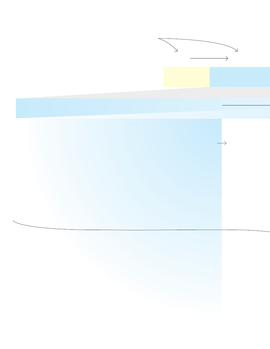
88
Goal-directed design process
after Alan Cooper (2001)
'OALS
0ERSONAS
/BSERVATIONS
)NTERVIEWS
!UDIT
$ESIGN/FFICE0RACTICES
$ESIGNER4ALENTAND3KILLS
3COPE
$ESIGN
)NITIATE
-ANAGERS
BUSINESSPLAN
MARKETINGPLAN
BRANDINGSTRATEGY
MARKETRESEARCH
PRODUCTPLAN
COMPETITORS
RELATEDTECHNOLOGY
MANAGEMENT
DOMAINEXPERTS
CUSTOMERS
PARTNERS
SALESCHANNEL
4HISSTEPLEADSTO
APROJECTMANDATE
USEPATTERNS
POTENTIALUSERS
THEIRACTIVITIES
THEIRENVIRONMENTS
THEIRINTERACTIONS
THEIROBJECTSTOOLS
AEIOUFRAMEWORKFROM
2ICK2OBINSON3APIENT
PRIMARY
SECONDARY
SUPPLEMENTAL
NEGATIVE
SERVEDINDIRECTLY
PARTNER
CUSTOMER
ORGANIZATIONAL
LIFE
END
EXPERIENCE
PERSONAL
PRACTICAL
CORPORATE
FALSE
DESIREDOUTCOMES
TIMECONSTRAINTS
FINANCIALCONSTRAINTS
GENERALPROCESS
MILESTONES
3COPEMAYBE
LOOSEORTIGHT
4HEWAYTHEOFFICEISSETUPANDRUNnTHEENVIRONMENT
THESPOKENANDUNSPOKENRULESnAFFECTTHEWORK
#OOPERSSTAFFDESCRIBESSEVERALKEYPRACTICES
GOALDIRECTEDDESIGNPROCESS
COLLABORATIVEENVIRONMENTANDCOMMONPURPOSE
$$#TEAMSTRUCTURESEESEPARATEDIAGRAM
EGOLESSDESIGN
APPROPRIATENESSOFASSIGNMENTS
COMMITMENTTOEDUCATION
COMMITMENTTOENHANCEPROCESS
ASSESSMENTANDSELFASSESSMENT
!DESIGNERSNATIVEABILITIESANDBACKGROUNDALSOAFFECT
THEWORK#OOPERLOOKSFORPEOPLEWITHTHESESKILLS
ANALYTIC
CONCEPTUAL
VISUAL
WRITTEN
COMMUNICATIONS
EMPATHIC
INTERPERSONAL
BRAINSTORMING
IMAGINATION
2EVIEWWHATEXISTS
EGDOCUMENTS
$ISCUSSVALUES
ISSUESEXPECTATIONS
!PPLYETHNOGRAPHIC
RESEARCHTECHNIQUES
$EFINETYPICAL
USERS
$EDUCEWHAT
USERSWANT
$EFINEINTENTAND
CONSTRAINTSOFPROJECT
!CTIVITY
2ESULT
!RTIFACT
3UMMARY
)NSIGHTS
4APES
4RANSCRIPTS
3UMMARY
)NSIGHTS
4APES
4RANSCRIPTS
3UMMARY
)NSIGHTS
.OTES
.OTES
0ROJECT"RIEF
-EETINGS
)NTERVIEWS
#HALKTALK
EARLYFINDINGS
#HALKTALKWITH
MANAGEMENT
"RIEFING
#OOPERPUTSUSERGOALSATTHECENTEROF
THESOFTWAREDESIGNPROCESS4HATPROCESS
ISPARTOFASERIESOFOFFICEPRACTICESWHICH
DEPENDONTHETALENTANDSKILLSOFDESIGNERS
ANDONTHEIRAPPLICATIONOFPRINCIPLESAND
PATTERNSTHROUGHOUTTHEPROCESS
4HISDIAGRAMSHOWSTHEPROCESSPROCEEDING
INSTEPSFROMLEFTTORIGHT)TLEAVESOUTFEED
BACKLOOPSANDITERATIONWHICHARENECESSARY
FORPRODUCINGGOODWORK
PROVIDEMANDATETO
$ESIGNERS
INSUREFINANCIALSUCCESS
0RIMARYRESPONSIBILITY
5SERS
LEADTO
2ESEARCHAND!NALYZE
PROVIDEINPUTTO
FOCUSINTHEFIRSTHALFCONTINUINGTHROUGHOUT
/PPORTUNITIES#ONSTRAINTSAND#ONTEXT
7HOWILLUSETHEPRODUCT
7HATPROBLEMWILLITSOLVEFORTHEM
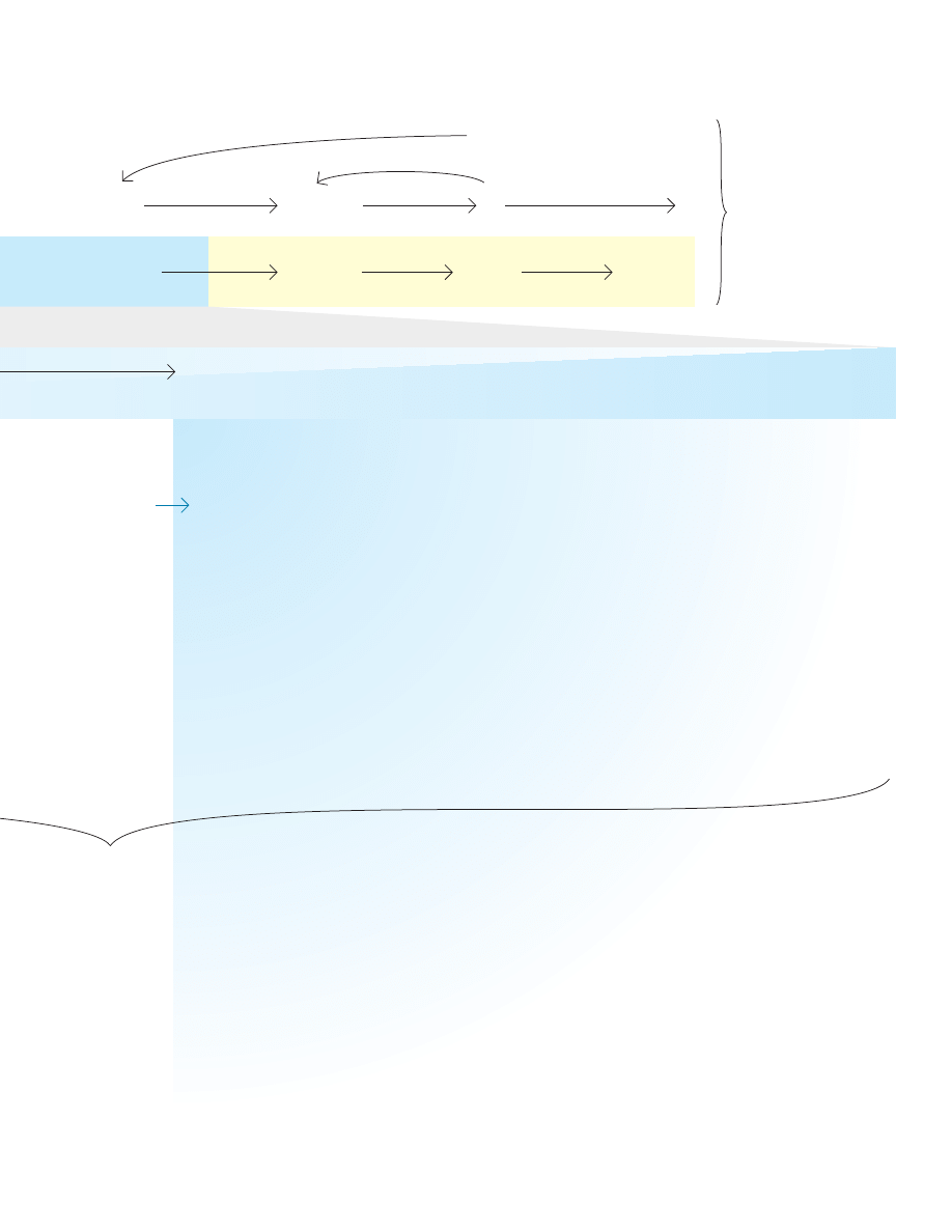
89
#ONCEPT
3CENARIOS
%LEMENTS
&RAMEWORK
3PEC
$ESIGN0RINCIPLES
#ODE
4EST
3HIP
PROBLEMDEFINITION
VISIONDEFINITION
DESIGNIMPERATIVES
-AYREQUIRECHANGES
INSCOPE
DAYINTHELIFE
KEYPATH
ERROR
SETUP
INFORMATIONOBJECTS
FUNCTIONALOBJECTS
CONTROLMECHANISMS
OBJECTRELATIONSHIPS
CONCEPTUALGROUPINGS
PATTERNS
LOGICNARRATIVEFLOW
NAVIGATIONSTRUCTURE
0RINCIPLESGUIDETHECHOICESDESIGNERSMAKEASTHEY
CREATE0RINCIPLESAPPLYATALLLEVELSOFDESIGNFROMBROAD
CONCEPTTOSMALLDETAIL&OREXAMPLE
$ONOHARM(IPPOCRATES
-EETUSERGOALS
#REATETHESIMPLESTCOMPLETESOLUTION/CKHAM&ULLER
#REATEVIABLEANDFEASIBLESYSTEMS
APPEARANCE
LANGUAGE
FLOWBEHAVIOR
PRODUCTCHARACTER
PRODUCTSTORY
4HROUGHOUTTHEGOALDIRECTEDDESIGNPROCESSDESIGNERSAPPLYOTHERPRACTICES
THEIRTALENTANDSKILLSASWELLASPRINCIPLESANDPATTERNS
3OFTWAREDEVELOPMENTPROCESS
&ORMAL$OCUMENT
0ROBLEM3TATEMENT
6ISION3TATEMENT
.OTES
3TORYBOARDS
,ISTS
3KETCHES
$IAGRAMS
(IGHLEVELDATAMODELS
3KETCHES
&LOW$IAGRAMS
&ORMAL$OCUMENT
$EMONSTRATION
0ROTOTYPE
0RESENTATION
#HALKTALKWITH
PROGRAMMERS
0RESENTATION
)MAGINEASYSTEMTO
HELPUSERSREACHGOALS
4ELLSTORIESABOUT
USINGTHESYSTEM
$ERIVECOMPONENTS
BASEDONUSERS
/RGANIZETHE
COMPONENTS
2EFINEDETAILS
DESCRIBEMODELS
PROVIDESPECTO
PROVIDECODETO
CERTIFYPRODUCTFORRELEASE
0ROGRAMMERS
1!
INSURECUSTOMERSATISFACTION
INSUREPERFORMANCE
INSURERELIABILITY
5SERS
DRIVE
SPARK
INFORM
MOTIVATE
FILTER
ORGANIZE
PRIORITIZE
INFLECT
VALIDATE
PROVIDEBUGREPORTSTO
3YNTHESIZEAND2EFINE
PROVIDEFEEDBACKONUSABILITYTO
ONGOINGTHROUGHOUTFOCUSINTHESECONDHALF
$ESIGN0ATTERNS
$ESIGNPATTERNSARERECURRINGFORMSORSTRUCTURESWHICH
DESIGNERSMAYRECOGNIZEORAPPLYnDURINGANALYSISAND
ESPECIALLYDURINGSYNTHESIS#HRISTOPHER!LEXANDER
h!0ATTERN,ANGUAGEvPROVIDESEXAMPLESOFPATTERNSFOR
ARCHITECTURE#OOPERCOLLECTSPATTERNSFORSOFTWARE
INTERACTION&OREXAMPLEACOMMONPATTERNISDIVIDINGA
WINDOWINTOTWOPANESTHELEFTSMALLERPANEPROVIDESTOOLS
ORCONTEXTANDTHERIGHTLARGERONEPROVIDESAWORKING
SPACEORDETAILS
4HEGOALDIRECTEDDESIGNPROCESSTAKESPLACEWITHINALARGERSOFTWAREDEVELOPMENTPROCESS
&ORM-EANINGAND"EHAVIOR
7HATISIT
(OWWILLITBEHAVEFORUSERS

90
Idealized process of developing buildings
after Alan Cooper (2004)
Since high school, architecture has fascinated Cooper. His
view of how architecture should be practiced provides a
model for how he believes software development should be
practiced. Cooper organized the process of developing a
building into three domains: architecture, engineering, and
construction. In his view, architects determine what the
building will be like (how it will “behave”). Based on the archi-
tect’s plans, engineers determine how to make the building
stand up. And fi nally, the builders execute the architect’s and
engineer’s plans. Obviously, architects serve their clients and
consult with engineers and builders on what is possible and
practical.
ARCHITECTS
DESIGN
FORMS
CREATINGPOTENTIALUSESFOR
REPRESENTEDINPLANS
CLIENTS
DEMONSTRATE
NEEDS
ARTICULATE
GOALS
ENGINEERS
DESIGN
STRUCTURES
ENSURINGSTABILITYANDSAFETYFOR
REPRESENTEDINPLANS
BUILDERS
BUILD
BUILDINGSFOR
INSPECTORS
MAYISSUE
PERMITS
WHICHALLOWOCCUPANCYBY
MAYREFUSE
ACCORDINGTOBUILDINGCODES
AREOBSERVEDBY
AREASSESSEDBY
WHICHREQUIRESCORRECTIONSFROM
PROVIDEABASISFOR
GUIDE
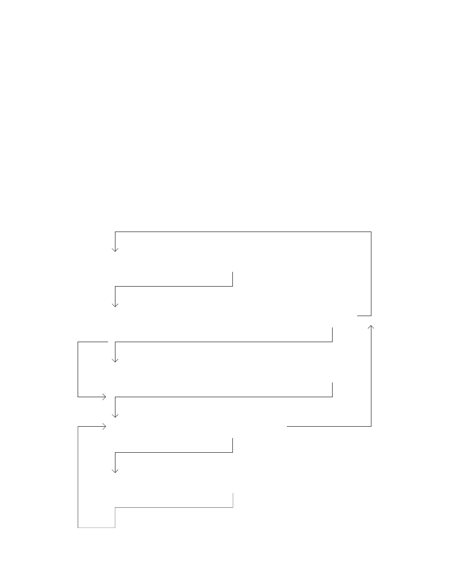
91
Idealized process of developing software
After Alan Cooper (2004)
Following his ideal model of architecture, Cooper advocated
organizing the process of developing software into three
domains: interaction design, engineering, and programming.
Interaction designers determine what the software will be like
(how it will “behave”). Based on the interaction designer’s
plans, engineers determine how to make the software work
by writing many very short test programs—but no fi nal code.
And fi nally, the programmers write real code to execute
the interaction designer’s and engineer’s plans. Here too,
Cooper acknowledges the need for feedback—for interac-
tion designers to observe users to understand their goals, to
consult with engineers to understand what’s possible, and
fi nally to consult with programmers to answer questions as
they program.
Cooper distinguishes engineers from programmers. Ac-
cording to him, engineers like to fi gure out how to solve
problems. They like to create and don’t want to be told what
to do. Programmers, he suggested, don’t like ambiguity.
They like to code and simply want to know what the code
is suppose to do. Cooper warned, putting an engineer in a
programming job or a programmer in an engineering job is a
recipe for unhappiness.
INTERACTIONDESIGNERS
DESIGN
FORMS
CREATINGPOTENTIALUSESFOR
BEHAVIORS
REPRESENTEDINPLANS
USERS
DEMONSTRATE
NEEDS
ARTICULATE
GOALS
ENGINEERS
DESIGN
PROGRAMSTRUCTURES
VERIFIEDBYSMALLPROTOTYPES
REPRESENTEDINSPECIFICATIONS
PROGRAMMERS WRITE
CODEWHICHISUSEDBY
TESTERS
FIND
BUGS
AREOBSERVEDBY
ISASSESSEDBY
WHICHREQUIRECORRECTIONSFROM
PROVIDEABASISFOR
WHICHAREIMPLEMENTEDBY

92
Morris Asimow
Asimow defi nes morphology of design as “the study of the
chronological structure of design projects.” He notes, “Each
design-project has an individual history which is peculiarly its
own. Nonetheless, as a project is initiated and developed, a
sequence of events unfolds in a chronological order forming
a pattern which, by and large, is common to all projects.” He
continues, “Design is a progression from the abstract to the
concrete. (This gives a vertical structure to a design project.)
. . . Design is [also] an iterative problem-solving process.
(This gives a horizontal structure to each design step.)”
Asimow defi nes the phases of a project (vertical) as
- Feasibility study
- Preliminary design
- Detailed design
- Planning for production
- Planning for distribution
- Planning for consumption
- Planning for retirement
He likened the design process (horizontal) to “the general
problem solving process,” describing these steps”
- analysis
- synthesis
- evaluation
- decision
- optimization
- revision
- implementation
In Introduction to Design, Asimow devotes more than 50
pages to describing engineering design and the design
process. He defi nes engineering design as “a purposeful
activity directed toward the goal of fulfi lling human needs,
particularly those which can be met by the technological fac-
tors of our culture. . . . As a profession, Engineering is largely
concerned with design. What distinguishes the objects of
engineering design from those of other design activities is
the extent to which technological factors must contribute to
their achievement.”
Asimow, like Alexander, Jones, and Doblin, distinguishes
craft-based design, “design by evolution,” from “design by
innovation.” He notes, “Now more frequently than ever in the
past, products are designed de novo,” and suggests this cre-
ates greater risk and complexity and thus implies the need
for new design tools (the subject of his book.)
According to Rowe (1987), Asimow was “an industrial en-
gineer prominent in the 1950s and 1960s.” Two years after
Asimow fi rst published his model, Tomas Maldonado and
Gui Bonsiepe introduced it to the design and architecture
community, including it in their seminal article “Science and
Design” published in the journal, Ulm 10/11 (1964).
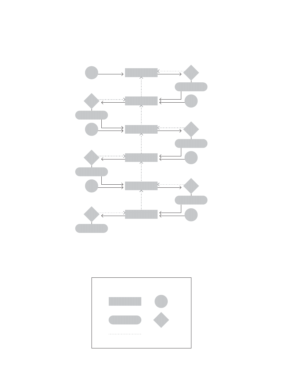
93
3TEP
$ESIGN0ROBLEM
3TEP
0HYSICAL2EALIZABILITY
3TEP
&INANCIAL&EASIBILITY
3TEP
3TEP
3YNTHESIS
3TEP
%CONOMIC7ORTH
3YMBOLOGY
0ROCESS
/UTCOME
)TERATIVEORFEEDBACKLOOP
)NFO
3OURCE
$ECISION
.EEDS!NALYSIS
3YSTEM)DENTIFICATION
$ESIGN#ONCEPTS
0HYSICAL!NALYSIS
%CONOMIC!NALYSIS
&INANCIAL!NALYSIS
%NGR3TATEMENT
OF0ROBLEM
-ARKET
)NFO
2ELEVANT
2EALIZABLE3OLUTIONS
#REATIVE
4ALENT
0OSSIBLE
3ETOF5SEFUL3OLUTIONS
%CON
&ACTORS
-ONEY
$ESIRED/UTPUTS
6ALID
!LTERNATIVE3OLUTIONS
4ECH
)NFO
0LAUSIBLE
7ORTHWHILE3OLUTIONS
4ECH
+NOWL
0AY
&INANCE
&ACTORS
0HASE&EASIBILITY3TUDY
Morphology of design (1 of 3)
after Morris Asimow (1962)
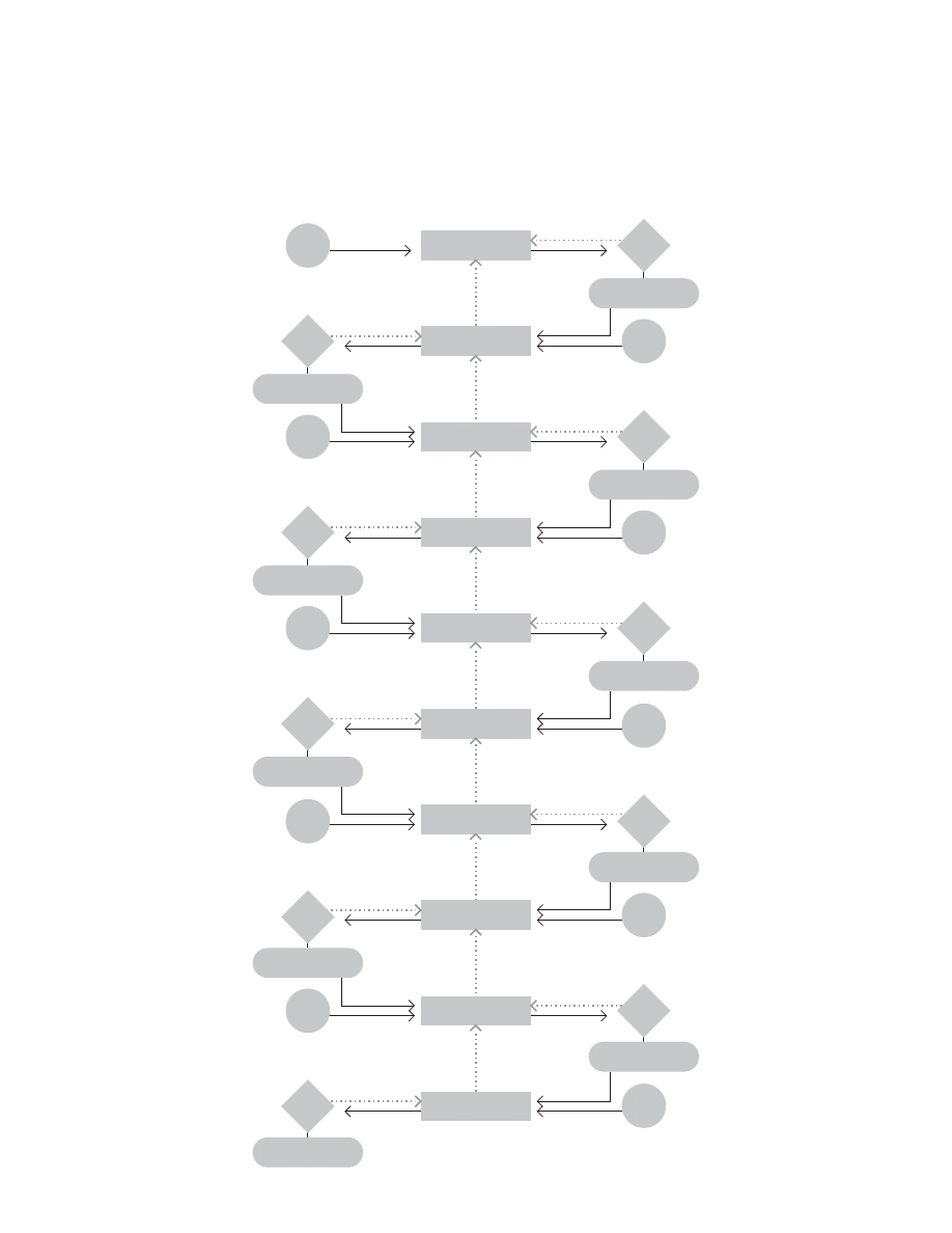
94
3TEP
3TEP
3TEP
3TEP
3TEP
3TEP
3TEP
3TEP
3TEP
3TEP
3ELECTIONOF
$ESIGN#ONCEPT
-ATHEMATICAL
!RCHETYPES
3ENSITIVITY!NALYSIS
#OMPATIBILITY!NALYSIS
3TABILITY!NALYSIS
/PTIMIZATION
0ROJECTION)NTO&UTURE
0REDICTIONOF"EHAVIOR
4ESTING
3IMPLIFICATION
!NALYTICAL&ORMULATION
%XP
4ECHN
6ALID
!DJUSTED0ARAMETERS
-ATH
!NALYSIS
&IT
/PTIMUM
-ATH
4EST
"EST
%XPECTED0ERFORMANCE
4RENDS
0ERFORM
!CCEPTED0ROPOSAL
,AB
4ECHNIC
"ETTER
4ENTATIVE3ELECTION
%XPER
IENCE
"EST
3ENSITIVE0ARAMETERS
%NGR
3CIENCE
7HICH
!DJUSTED&OR3TABILITY
4ECH
)NFO
3TABLE
"EHAVIOR/VER4IME
-ATH
4IME
4EST2ESULTS
-ATH
4EST
7ORK
0HASE0RELIMINARY$ESIGN
Morphology of design (2 of 3)
after Morris Asimow (1962)
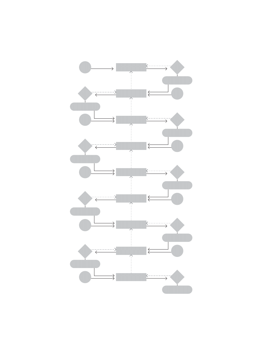
95
3TEP
3TEP
3TEP
3TEP
3TEP
3TEP
3TEP
3TEP
3TEP
0REPARATION&OR$ESIGN
$ESCRIPTION
3UBSYSTEMS
$ESCRIPTION
#OMPONENTS
$ESCRIPTIONOF0ARTS
!SSEMBLY$RAWINGS
%XPERIMENTAL
#ONSTRUCTION
0RODUCT4EST0ROGRAM
!NALYSIS0REDICTION
2EDESIGN
3UBSYSTEM#ONCEPTS
%XPER
IENCE
'OOD
3PECIFICATIONS
AND$RAWINGS
4ECHN
+NOWL
'OOD
0ROTOTYPE
4ECHN
%XPER
0RODUCE
IBLE
$ETECTED&LAWS
,AB
'OOD
4ECHN
+NOWL
"UDGET/RGANIZATION
6ALID
#OMPONENT#ONCEPTS
4ECHN
+NOWL
'OOD
#OMPLETE$ESCRIPTIONS
4ECHN
+NOWL
&IT
4EST$ATA
3HOP
$OES
)T7ORK
)MPROVED$ESIGN
-ATH
!NALYSIS
"ETTER
0HASE$ETAILED$ESIGN
Morphology of design (2 of 3)
after Morris Asimow (1962)

96
Bruce Archer
Cross (1984) notes, “One of the fi rst tasks attempted by the
design methodologists was the development of new, sys-
tematic design procedures.” He calls out four authors as es-
pecially important: Jones, Alexander, Archer, and Rittel. (For
more on Jones, see pages 56-59; for more on Alexander, see
page 18.) This section presents three models from Archer.
(Rittel came to see design as a process of argumentation
aimed at coming to agreement on goals; as far as I know, he
presented no staged or procedural models of design.)
Archer taught at both the Royal College of Art (RCA) in
London and the Hochschule für Gestaltung in Ulm (HfG Ulm).
Rowe (1987) notes that at Ulm, “speculation moved beyond
description and explanation of design behavior and into the
realm of idealization. Not only was the possibility of a ‘scien-
tifi c’ and totally objective approach toward design seriously
entertained, it became a goal in itself. A confi dent sense of
rational determinism prevailed; the whole process of de-
sign, it was believed, could be clearly and explicitly stated,
relevant data gathered, parameters established, and an ideal
artifact produced.”
Archer’s statements about the design process contradict
Rowe’s critique, “The fact is that being systematic is not nec-
essarily synonymous with being automated.” Archer contin-
ues, “When all has been said and done about defi ning design
problems and analyzing design data, there still remains the
real crux of the act of designing—the creative leap from
pondering the question to fi nding a solution. . . . If we accept
that value judgments cannot be the same for all people, for
all places or all time, then it follows that neither the designer
nor his client (nor, eventually, the user) can abdicate the re-
sponsibility for setting up his own standards. Similarly, there
is no escape for the designer from the task of getting his own
creative ideas. After all, if the solution to a problem arises
automatically and inevitably from the interaction of the data,
then the problem is not, by defi nition, a design problem.”

97
Biological sequence of problem solving
after Bruce Archer (1963-1964)
Archer notes the similarity of biological response mecha-
nisms and problem solving in computer programming and
design. And he explicitly links these processes to cybernet-
ics.
“The study of control mechanisms of living organisms is
called cybernetics. In recent times, designers of highly
complicated control systems for machine tools, aeroplanes,
rockets and remote controlled instruments have turned to
cybernetics for inspiration.”
“A further line of thinking which does not quite fall into this
pattern but which has contributed to the development of
systematic methods for designers is the ‘heuristic’. an
ancient philosophical study of the method of intellectual
discovery which has been revitalized recently by Professor
[George] Polya of Stanford University, USA.”
“The method for solving design problems set out in this ar-
ticle owes something to both the heuristic and the cybernetic
approaches.” (See Polya’s model on page 36. See models
from cybernetics on pages 117-118.)
$ISCERN@SOMETHINGWRONG
(EIGHTENALERTNESSANDLOCATETHEAREAOFDISTURBANCE
"RINGAPPROPRIATESENSEORGANSTOBEAR
%VALUATEEVIDENCEANDCOMPAREWITHPREVIOUSEXPERIENCES
0OSTULATEAPOSSIBLECAUSEFORTHEDISTURBANCE
2ECALLEXPERIENCEWITHSIMILARANDORANALOGOUSCAUSES
0REDICTCONSEQUENCEOFSUGGESTEDCAUSE
&ORMULATECOURSESOFACTIONPOSSIBLEINRESPONSETOSUCHACAUSE
2ECALLEXPERIENCEWITHSIMILARANDORANALOGOUSCOURSEOFACTION
0REDICTCONSEQUENCESOFEACHSUGGESTEDCOURSEOFACTION
3ELECTCOURSEOFACTIONTOBEFOLLOWED
!CT
$ISCERNEFFECTOFACTION
2ECALLEXPERIENCEWITHSIMILARANDORANALOGOUSEFFECTS
2EPEATFROMUNTILEQUILIBRIUMISRESTORED
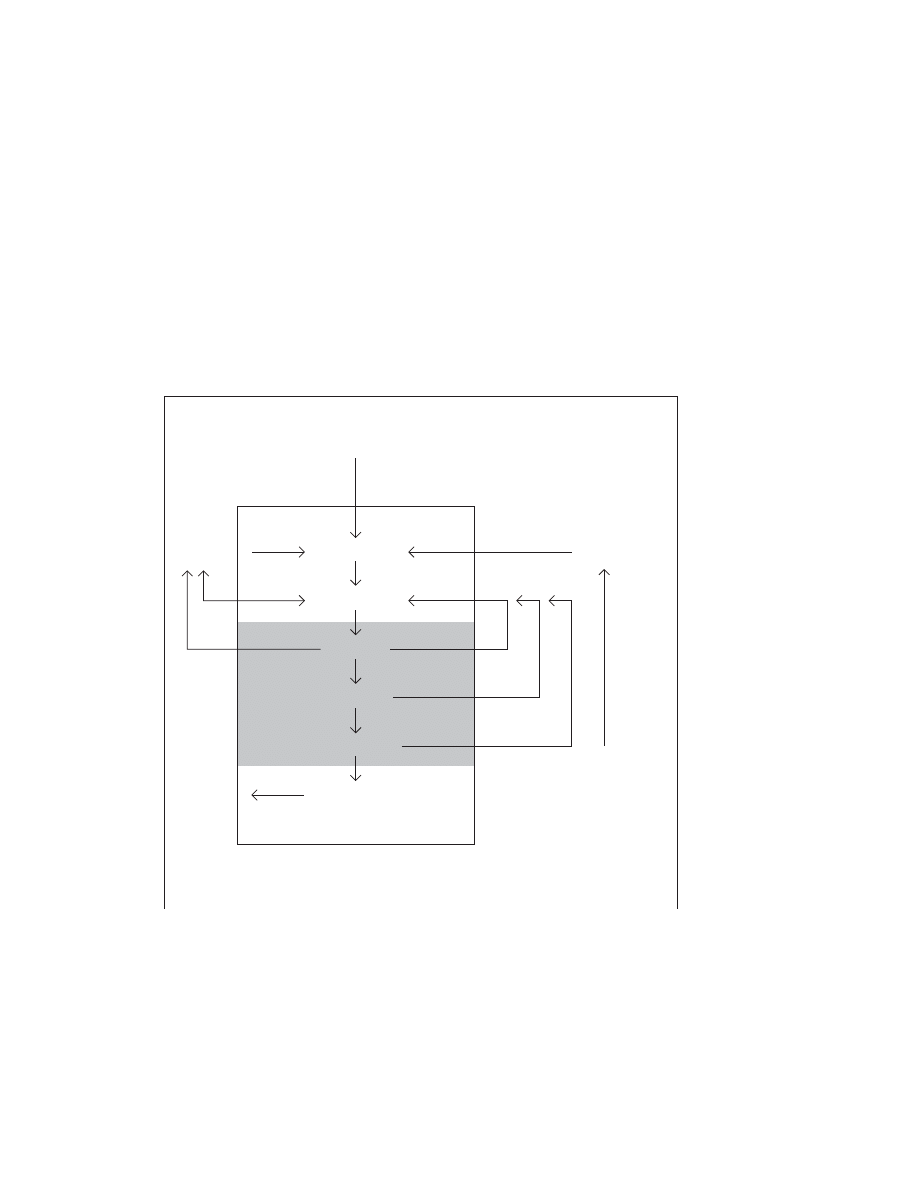
98
4RAINING
"RIEF
0ROGRAMMING
3OLUTION
%XPERIENCE
$ATA#OLLECTION
!NALYSIS
3YNTHESIS
$EVELOPMENT
#OMMUNICATION
!NALYTICAL0HASE
#REATIVE0HASE
%XECUTIVE0HASE
/BSERVATION
-EASUREMENT
)NDUCTIVE2EASONING
%VALUATION
*UDGMENT
$EDUCTIVE2EASONING
$ESCRIPTION
4RANSLATION
4RANSMISSION
Basic design procedure
after Bruce Archer (1963-1964)
This diagram was reprinted in the journal Ulm (1964) and
several other places, e.g., Cross (1984, 2000) and Rowe
(1987). Archer proposed this model as representative of an
emerging “common ground” within the “science of design
method” even while acknowledging continuing “differences”.
Regarding the procedure, he points out, “In practice, the
stages are overlapping and often confused, with frequent
returns to early stages when diffi culties are encountered and
obscurities found.”
He continues, “The practice of design is thus a very compli-
cated business, involving contrasting skills and a wide fi eld
of disciplines. It has always required an odd kind of hybrid to
carry it out successfully. The more sophisticated the de-
mands of function and marketing become, the harder the job
of the designer will get. Already it has become too compli-
cated for the designer to be able to hold all the factors in his
mind at once.”

#HECK,ISTFOR0RODUCT$ESIGNERS
&ORWARD3UMMARY
4HECHECKLISTWHICHACCOMPANIEDTHEORIGINALSERIESOFARTICLESIN
$ESIGNWASREGARDEDBYTHEAUTHORASTHEEMBODIMENTOFA
HYPOTHESISONTHESTRUCTUREOFTHEDESIGNACT3INCETHISWAS
PUBLISHEDFURTHERFUNDAMENTALSTUDYHASBEENUNDERTAKEN
4HEFOLLOWINGCHECKLISTISTHUSPRESENTEDASASECONDHYPOTHESIS
WHICHTHEAUTHORRECOGNIZESASSTILLNAIVEINPLACES)TISNOT
INTENDEDTOBEREADASANARRATIVE.EVERTHELESSSTUDYOFTHE
SUMMARYBELOWMIGHTBEUSEFULINPRESENTINGANOVERALLPICTUREOF
DESIGNPROCEDURE4HEREMAINDEROFTHECHECKLISTISOFFEREDASA
DESIGNTOOLCALCULATEDTOBEUSEFULINTHECONTROLOFMOSTNORMAL
PRODUCTDESIGNPROJECTS
(OWTOUSECHECKLISTANDARROWDIAGRAMS
4HECHECKLISTHASBEENSETOUTINTHEFORMOFALISTOFACTIVITIESAND
EVENTSACCORDINGTOTHECONVENTIONSOFNETWORKANALYSIS
)TISSUGGESTEDTHATTHEDIAGRAMAPPROPRIATETOTHEPHASEWHICHHAS
BEENREACHEDINTHEDESIGNPROJECTINQUESTIONSHOULDBEMOUNTED
ONTHEWALLADJACENTTOTHEDESIGNERgSDRAWINGBOARD!STHEWORK
PROGRESSESTHEDESIGNERSHOULDIDENTIFYEVENTSINTHECHECKLISTAS
THEYTAKEPLACEANDTICKTHEMOFFONTHEDIAGRAM4HELINKSINTHE
DIAGRAMSHOWWHATMUSTBEDONENEXT4ARGETDATESANDOR
ESTIMATEDWORKINGHOURSCANBEADDEDWHEREAPPROPRIATE
0HASEn0REPAREMANUFACTURINGDOCUMENTATION
#OMMUNICATION
$EFINE#OMMUNICATION.EEDS
3ELECT#OMMUNICATION-EDIUM
0REPARE#OMMUNICATION
7INDING5P
7IND5P0ROJECT
#LOSE2ECORDS
0HASEn0REPAREOUTLINEDESIGNPROPOSALS
3YNTHESIS
2ECEIVE)NSTRUCTIONS
2ESOLVE2EMAINING0ROBLEMS!BOUT%NDS
0OSTULATE-EANS&OR2ECONCILING$IVERGENT$ESIDERATA)N0ERFORMANCE3PECIFICATION
$EVELOP3OLUTIONS)N0RINCIPLETO0ROBLEMS!BOUT-EANS!RISING&ROM0ERFORMANCE3PECIFICATION
0OSTULATE/UTLINE/VERALL3OLUTIONS
0HASE
0RELIMINARIES
2ECEIVE%NQUIRY
%VALUATE%NQUIRY
%STIMATE/FFICE7ORK,OAD
0REPARE0RELIMINARY2ESPONSE
0HASEn2ECEIVEBRIEFANALYZEPROBLEMPREPAREDETAILEDPROGRAMMEANDESTIMATE
"RIEFING
2ECEIVE)NSTRUCTIONS
$EFINE'OALS
$EFINE#ONSTRAINTS
0ROGRAMMING
%STABLISH#RUCIAL)SSUES
0ROPOSE!#OURSE/F!CTION
0HASEn#OLLECTDATAPREPAREPERFORMANCEORDESIGNSPECIFICATIONREAPPRAISEPROPOSEDPROGRAMMEANDESTIMATE
$ATA#OLLECTION
2ECEIVE)NSTRUCTIONS
#OLLECT2EADILY!VAILABLE)NFO
#LASSIFY!ND3TORE$ATA
!NALYSIS
)DENTIFY3UBPROBLEMS
!NALYZE3UBPROBLEMS!BOUT%NDS
0REPARE0ERFORMANCE3PECIFICATION
2EAPPRAISE0ROGRAM!ND%STIMATE
0HASEn$EVELOPPROTOTYPEDESIGNS
$EVELOPMENT
2ECEIVE)NSTRUCTIONS
$EFINE$ESIGN)DEA
%RECT!+EY-ODEL
$EVELOP3UBPROBLEM-UTUAL3OLUTION
$EVELOP/VERALL3OLUTIONS
0HASEn0REPAREANDEXECUTEVALIDATIONSTUDIES
$EVELOPMENT#ONTINUED
6ALIDATE(YPOTHESES
99
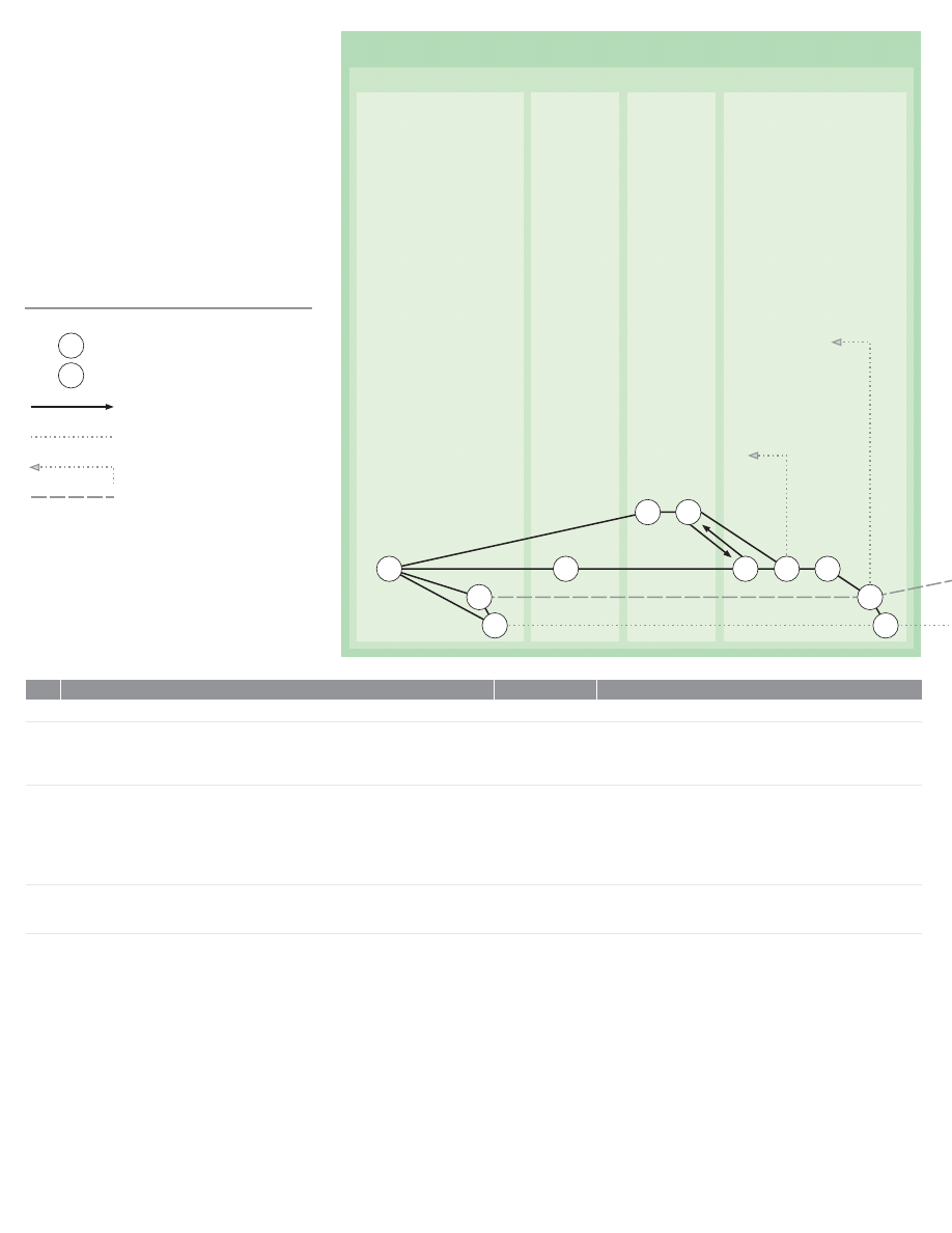
0HASE
0RELIMINARIES
2ECEIVE%NQUIRY
%VALUATE%NQUIRY
%STIMATE/FFICE
7ORK,OAD
0REPARE0RELIMINARY2ESPONSE
0RELIMINARIES
2ECEIVE%NQUIRY
3END!CKNOWLEDGMENT
/PEN0ROJECT&ILE
#OMMENCE#HART&OR2ECORDING0ROGRESS
%VALUATE%NQUIRY&OR%XAMPLE
)DENTIFY!UTHORITY4O7HOM!NSWERABLE
)DENTIFY4YPE/F4ASK
)DENTIFY#LASSOF0RODUCT
$EFINE&ORM/F3UBMISSION2EQUIRED
$EFINE!NY&ACILITY/R&REE3TRUCTURE/FFERED
$EFINE!NY0ROGRAM,IMITATIONS)MPOSED
%STIMATE/FFICE7ORK,OAD
3URVEY%XISTING!ND0ROJECTED0ROGRAMMED
%STIMATE-ANPOWER!VAILABILITY
0REPARE0RELIMINARY2ESPONSE
"REAK$OWN4ASK$ESCRIBED5NDER)NTO!N/UTLINE0ROGRAM
-ATCH/UTLINE0ROGRAM7ITH-ANPOWER!VAILABILITY%STIMATE3ET/UT5NDER
0REPARE0RELIMINARY%STIMATE/F#OSTS
&ORMULATE!$RAFT0ROPOSAL
#HECK$RAFT0ROPOSAL%STIMATE
)F.ECESSARY2EITERATE&ROM5NTIL!3ATISFACTORY0ROPOSAL)S$RAFTED
0REPARE!ND$ISPATCH&AIR#OPY/F0ROPOSAL!ND%STIMATE
"RING&ILE!ND0ROGRESS-ACHINERY5PTODATE
2EITERATE3ECTION5NTIL!GREEMENT)S!CHIEVED/N!#OMMISSION4O#ARRY/UT0HASE
2ECEIVE"RIEF!NALYZE0ROBLEM0REPARE$ETAILED0ROGRAM!ND%STIMATE/R5NTIL
0ROJECT)S!BANDONED
%NQUIRY2ECEIVED
!CKNOWLEDGMENT$ISPATCHED
0ROJECT&ILE!ND0ROGRESS-ACHINERY2EADY
2EPORT/N%VALUATION/F%NQUIRY2EADY
3URVEY/F/FFICE7ORKLOAD2EADY
%STIMATE/F-ANPOWER!VAILABILITY2EADY
/UTLINE0ROJECT0ROGRAM2EADY
$RAFT0ROPOSAL!ND%STIMATE2EADY
$RAFT0ROPOSAL!ND%STIMATE!PPROVED
0ROPOSAL!ND%STIMATE$ISPATCHED
&ILES!ND0ROGRESS-ACHINERY5P4O$ATE
%VENT
2EPEATED%VENT
!CTIVITY
#ARRY&ORWARD
2EPEAT)F.ECESSARY
&ROM%VENT)NDICATED
7AITING4IME
+EY
N
%XPLANATION
)NTHEDIAGRAMSTIMEFLOWSFROMLEFTTORIGHTACROSSTHEPAGEEACH
ARROWREPRESENTSANONGOINGACTIVITYWHICHTAKESAGREATERORLESSER
AMOUNTOFTIME(OWEVERTHEREISNOTATTEMPTTOMAKETHELENGTHOF
THEARROWPROPORTIONALTOTHETIMETAKENBYTHEACTIVITY4HECIRCLESAT
EACHENDOFTHEARROWREPRESENTTHEEVENTSWHICHOPENANDCLOSEAN
ACTIVITY%VENTSOCCURATANINSTANTINTIMERATHERTHANOVERAPERIOD
OFTIME3OMETIMESMORETHANONEACTIVITYISREQUIREDTOCOMPLETE
ANEVENT3OMETIMESANEVENTPERMITSMORETHANONEACTIVITYTO
COMMENCE%VENTSWITHTHESUFFIXNMUSTBEREPEATEDANUMBEROF
TIMESFORDIFFERENTSUBPROBLEMS
4HECONVENTIONSDESCRIBEDARECOMMONTOVARIOUSFORMSOFNETWORK
ANALYSISFOREXAMPLECRITICALPATHPLANNINGAND0%24
!CTIVITY
!CTIVITY.O
%VENT
)TEM
100
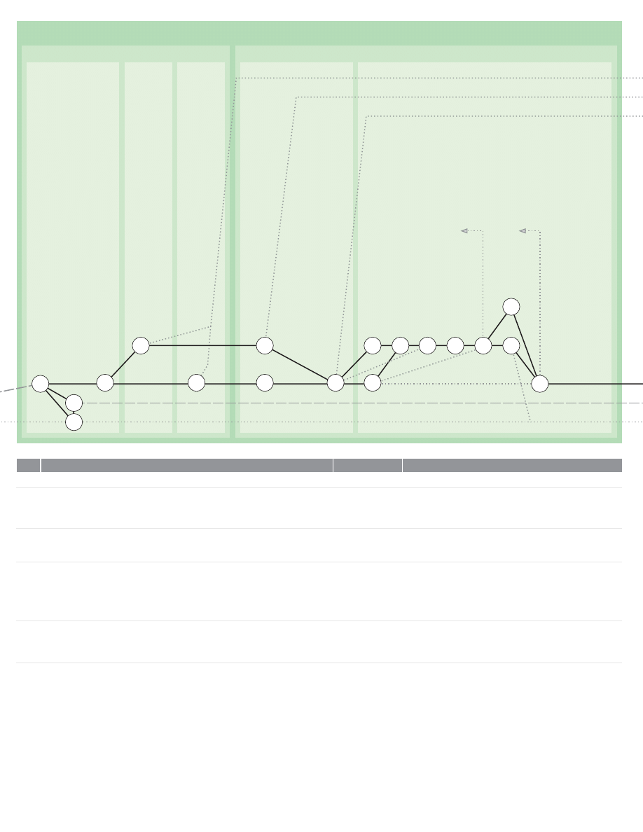
0HASE
"RIEFING
2ECEIVE)NSTRUCTIONS
$EFINE'OALS
%STABLISH#RUCIAL)SSUES
0ROPOSE!#OURSE/F!CTION
$EFINE
#ONSTRAINTS
0ROGRAMMING
N
N
"RIEFING
2ECEIVE)NSTRUCTIONS
3END!CKNOWLEDGMENT
"RING&ILES!ND0ROGRESS-ACHINERY5P4O$ATE
-AKE!RRANGEMENTS&OR&ORMAL"RIEFING
$EFINE'OALS&OR%XAMPLE
$EFINE#LIENTgS#ORPORATE0OLICY4RADING0OLICY0ROJECT!IMS0ROBLEM!IMS)DENTIFY2EASONS&OR
%XAMINING0ROBLEM.OW$EFINE$ESIGN'OALS
$EFINE#ONSTRAINTS&OR%XAMPLE
)DENTIFY!NY.ATIONAL#ONSTRAINTS!NY4RADE#ONSTRAINTS!NY-ANDATORY#OMPANY#ONSTRAINTS
!NY#ONTRACTUAL#ONSTRAINTS"UDGETARY#ONSTRAINTS-ARKETING#ONSTRAINTS-ANUFACTURING
#ONSTRAINTS!NY/THER#ONSTRAINTS
0ROGRAMMING
%STABLISH#RUCIAL)SSUES
!NALYZE'OALS2ECORDED5NDER!ND$EFINE#RITERIA&OR-EASURING3UCCESS
!NALYZE#ONSTRAINTS)DENTIFIED5NDER!ND$EFINE&IELD!VAILABLE&OR-ANEUVER
)DENTIFY#RUCIAL)SSUES
0ROPOSE!#OURSE/F!CTION
2EVIEW%XPERIENCE/F!NALOGOUS0ROBLEMS
#OLLECT#ASE(ISTORIES/F3IMILAR0ROBLEMS(ANDLED%LSEWHERE
,IST#OURSES/F!CTION!VAILABLE
3ELECT!0ROMISING#OURSE/F!CTION
4EST3ELECTED#OURSE/F!CTION!0ILOT3TUDY
)N4HE,IGHT/F%XPERIENCE7ITH!NALOGOUS0ROBLEMS!PPRAISE0ROBABLE!DEQUACY/F
#OURSE/F!CTION3ELECTED
)F.ECESSARY2EITERATE&ROM5NTIL!3UFFICIENTLY!SSURING#OURSE/F!CTION)S3ELECTED
2EAPPRAISE/FFICE7ORKLOAD!ND0ROJECT&ACILITIES
2EAPPRAISE0ROGRAM!ND4IMETABLE
&ORMULATE$RAFT2EVISE0ROPOSAL!ND%STIMATE7ITH3PECIAL2EPORTS/N!ND)F
.ECESSARY
#OMMISSION2ECEIVED4O%XECUTE0HASE
!CKNOWLEDGMENT$ISPATCHED
&ILE!ND0ROGRESS-ACHINERY5P4O$ATE
!RRANGEMENTS#OMPLETE&OR&ORMAL"RIEFING
$EFINITION/F'OALS#OMPLETE
$EFINITION/F#ONSTRAINTS#OMPLETE
#RITERIA&OR-EASURING3UCCESS)DENTIFIED
&IELD&OR-ANEUVER$EFINED
#RUCIAL)SSUES)DENTIFIED
2EVIEW/F%XPERIENCE7ITH!NALOGOUS0ROBLEMS#OMPLETE
#OLLECTION/F#ASE(ISTORIES2EADY
!VAILABLE#OURSES/F!CTION,ISTED
!0ROMISING#OURSE/F!CTION3ELECTED
4EST/F3ELECTED#OURSE/F!CTION#OMPLETED
!PPRAISAL/F0ROBABLE!DEQUACY#OMPLETE
2EAPPRAISAL/F/FFICE7ORK,OAD!ND0ROJECT&ACILITIES#OMPLETE
2EAPPRAISAL/F0ROJECT0ROGRAM!ND4IMETABLE#OMPLETE
$RAFT2EVISED0ROPOSAL!ND%STIMATE2EADY
!CTIVITY
!CTIVITY.O
%VENT
)TEM
101
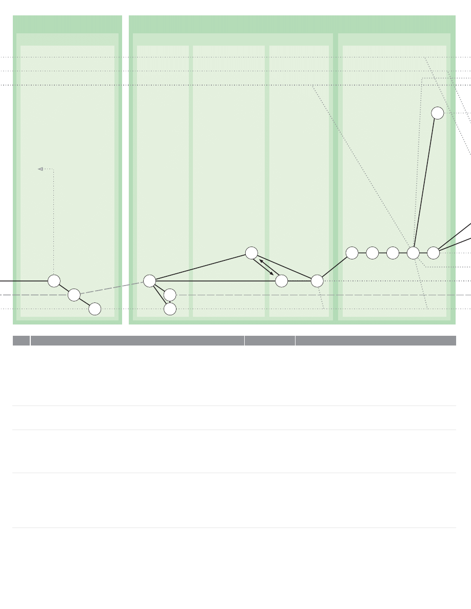
)DENTIFY3UB0ROBLEMS
0HASE
$ATA#OLLECTION
0HASE#ONTINUED
0ROGRAMMING#ONTINUED
0ROPOSE!#OURSE/F!CTION#ONTINUED
2ECEIVE)NSTRUCTIONS
#OLLECT2EADILY!VAILABLE)NFO
#LASSIFY!ND3TORE$ATA
!NALYSIS
N
#HECK$RAFT0ROPOSAL!ND%STIMATE
)F.ECESSARY2EITERATE&ROM5NTIL!3ATISFACTORY0ROPOSAL)S$RAFTED
0REPARE!ND$ISPATCH&AIR#OPY/F0ROPOSAL!ND%STIMATE
"RING&ILE!ND0ROGRESS-ACHINERY5P4O$ATE
2EITERATE3ECTIONS!ND5NTIL!GREEMENT)S2EACHED4O#ARRY/UT0HASE#OLLECT$ATA
0REPARE0ERFORMANCE3PECIFICATION2EAPPRAISE0ROPOSED0ROGRAM!ND%STIMATE/R5NTIL
0ROJECT)S!BANDONED
$ATA#OLLECTION
2ECEIVE)NSTRUCTIONS
3END!CKNOWLEDGMENT
"RING&ILES!ND0ROGRESS-ACHINERY5P4O$ATE
#OLLECT2EADILY!VAILABLE)NFORMATION&OR%XAMPLE/N
%NVIRONMENTAL!T0OINT/F5SE)DENTITY/F5SERS5SER%RGONOMICS5SER-OTIVATION
0RODUCT&UNCTION0RODUCT-ECHANICS0RODUCT&INISH0RODUCT!ESTHETICS-ARKET%NVIRONMENT
#OMPETITIVE0RODUCTS0RODUCT!RCHETYPE"RAND0REDECESSORS-AKERgS(OUSE3TYLE
2ULING-ARKET0RICES%CONOMIC1UANTITIES0RODUCT&ACILITIES,IMITING$IMENSIONS-ATERIALS
#OLLECT/THER2EADILY!VAILABLE)NFORMATION
#LASSIFY!ND3TORE$ATA
,IST)NFORMATION4OPICS(ANDLED
2ATIONALIZE4OPIC(EADINGS
$ESIGN!N)NFORMATION#LASSIFICATION3YSTEM
#LASSIFY!LL)NFORMATION(ELD
3HELVE4HE)NFORMATION'ATHERED
!NALYSIS
)DENTIFY3UBPROBLEMS
,IST!LL4HE&ACTORS)N4HE/VERALL0ROBLEM
0AIR)NTERDEPENDENT&ACTORS3O!S4O&ORM!LL-ATTERS)NTO3UB0ROBLEMS
,IST!LL4HE3UBPROBLEMS4HUS)DENTIFIED
)DENTIFY4HE!PPARENT3EQUENCE/F$EPENDENCE/F3UBPROBLEMS5PON/NE!NOTHER
$RAFT2EVISED0ROPOSAL!ND%STIMATE!PPROVED
2EVISED0ROPOSAL!ND%STIMATE$ISPATCHED
&ILES!ND0ROGRESS-ACHINERY5P4O$ATE
#OMMISSION2ECEIVEDTO%XECUTE0HASE
!CKNOWLEDGMENT$ISPATCHED
&ILES!ND0ROGRESS-ACHINERY5P4O$ATE
!VAILABLE)NFORMATION2EADY
,IST/F)NFORMATION2EADY
!VAILABLE)NFORMATION#LASSIFIED!ND3HELVED
,IST/F&ACTORS2EADY
)NTERDEPENDENCE-ATRIX2EADY
,IST/F3UBPROBLEMS2EADY
3UB0ROBLEM.ETWORK2EADY
!CTIVITY
!CTIVITY.O
%VENT
)TEM
102
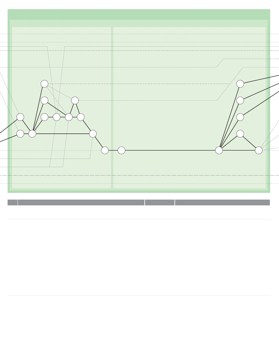
0HASE#ONTINUED
!NALYSIS#ONTINUED
!NALYZE3UBPROBLEMS!BOUT%NDS
0REPARE0ERFORMANCE3PECIFICATION
N
N
N
N
N
N
N
N
N
N
N
$ISTINGUISH0ROBLEMS!BOUT-EANS&ROM
0ROBLEMS!BOUT%NDS
2ESOLVE0ROBLEMS!BOUT%NDS!S)NDICATED)N3ECTIONS!ND
!NALYZE3UBPROBLEMS!BOUT%NDS
3ELECT!0ROBLEM!BOUT%NDS&ROM4HE.ETWORK)DENTIFIED5NDER
,IST4HE&ACTORS)N4HIS3UBPROBLEM
)DENTIFY4HE'OAL4O"E!CHIEVED
%STABLISH4HE#ONNECTION"ETWEEN4HE&ACTORS!ND4HE'OAL
)DENTIFY4HOSE&ACTORS7HERE4HE$ATA6ALUES-AY"E6OLUNTARILY&IXED
"Y4HE$ESIGNER
)DENTIFY4HOSE&ACTORS7HERE4HE$ATA6ALUES!RE&IXED"Y%XTERNAL)NFLUENCES
)DENTIFY4HOSE&ACTORS7HERE4HE$ATA!RE$EPENDENT6ARIABLES&OR%XAMPLE7HERE
4HE$ATA!RE4HE3OLUTIONS4O/THER3UBPROBLEMS
)F.ECESSARY2EVISE.ETWORK)N3O4HAT0ROBLEMS7HICH0ROVIDE$ATA&OR/THER
0ROBLEMS!RE$EALT7ITH)N4HE2IGHT/RDER/R3ELECT!NOTHER0ROBLEM!T
#OLLECT.ECESSARY$ATA%ITHER%XTRACT$ATA&ROM2ECORD3YSTEM/R!DD&RESH$ATA
7HERE3UFFICIENT0RECISE$ATA)S!VAILABLE$ELINEATE-AXIMUM&IELD/F&EASIBLE3OLUTIONS
7HERE3UFFICIENT0RECISE$ATA)S.OT!VAILABLE0OSTULATE3IMPLIFYING
!SSUMPTIONS"Y0LAUSIBLE2EASONING!ND4HEN$ELINEATE!&IELD/F
&EASIBLE3OLUTIONS
2EFERRING4O)DENTIFY4HE:ONE7HERE3ATISFACTION/F'OAL)S/PTIMUM
2EEXAMINE3ECTION!ND-ODIFY0ROBLEM.ETWORK!S.ECESSARY
2EITERATE3ECTION/F%ACH0ROBLEM!BOUT%NDS)N4HE.ETWORK
0REPARE0ERFORMANCE3PECIFICATION
4AKING%VERY#OMBINATION/F0AIRS/F3UBPROBLEMS!BOUT%NDS)DENTIFY7HICH)N%ACH0AIR
-UST4AKE0RECEDENCE)F4HEIR/PTIMUM3OLUTIONS!RE)NCOMPATIBLE
2ANK4HE#OMPLETE,IST/F3UBPROBLEMS)N/RDER/F0RECEDENCE
)DENTIFY4HOSE0AIRS7HERE4HE/PTIMUM3OLUTIONS!RE)N&ACT-UTUALLY#OMPATIBLE2EFERRING
4O&OR%ACH3UBPROBLEM
)DENTIFY4HOSE0ARIS7HERE4HE/PTIMUM3OLUTION/F/NE)S#OMPATIBLE7ITH&EASIBLE"UT
.OT4HE/PTIMUM3OLUTIONS/F4HE/THER
)DENTIFY4HOSE0AIRS7HERE&EASIBLE3OLUTIONS"UT.OT4HE/PTIMUM3OLUTIONS
!RE#OMPATIBLE
)DENTIFY4HOSE0AIRS7HERE&EASIBLE3OLUTIONS!ND/PTIMUM3OLUTIONS!RE)NCOMPATIBLE
,ISTOF0ROBLEMS!BOUT-EANS2EADY
,IST/F0ROBLEMS!BOUT%NDS2EADY
,IST/F&ACTORS)N3UBPROBLEM2EADY
'OALS!ND#ONDITIONS)DENTIFIED
#ONNECTION"ETWEEN&ACTORS!ND'OALS/R
#ONDITIONS%STABLISHED
6OLUNTARILY%VALUABLE&ACTORS)DENTIFIED
%XTERNALLY)NFLUENCED&ACTORS)DENTIFIED
$EPENDENTLY6ARIABLE&ACTORS)DENTIFIED
2EVISED.ETWORK2EADY
.ECESSARY$ATA2EADY
3IMPLIFYING!SSUMPTIONS0OSTULATED
&IELD/F&EASIBLE3OLUTIONS$ELINEATED
/PTIMAL3OLUTION)DENTIFIED
!LL0ROBLEMS!BOUT%NDS2ESOLVED
0RIORITIES)DENTIFIED2ANKING-ATRIX
2ANKED,IST/F0ROBLEMS!BOUT%NDS2EADY
0ROBLEMS7ITH#OMPATIBLE/PTIMAL3OLUTIONS)DENTIFIED
0ROBLEMS7ITH#OMPATIBLE/PTIMAL&EASIBLE3OLUTIONS
)DENTIFIED
0ROBLEMS7ITH#OMPATIBLE&EASIBLE3OLUTIONS)DENTIFIED
0ROBLEMS7ITH)NCOMPATIBLE3OLUTIONS)DENTIFIED
!CTIVITY
!CTIVITY.O
%VENT
)TEM
103
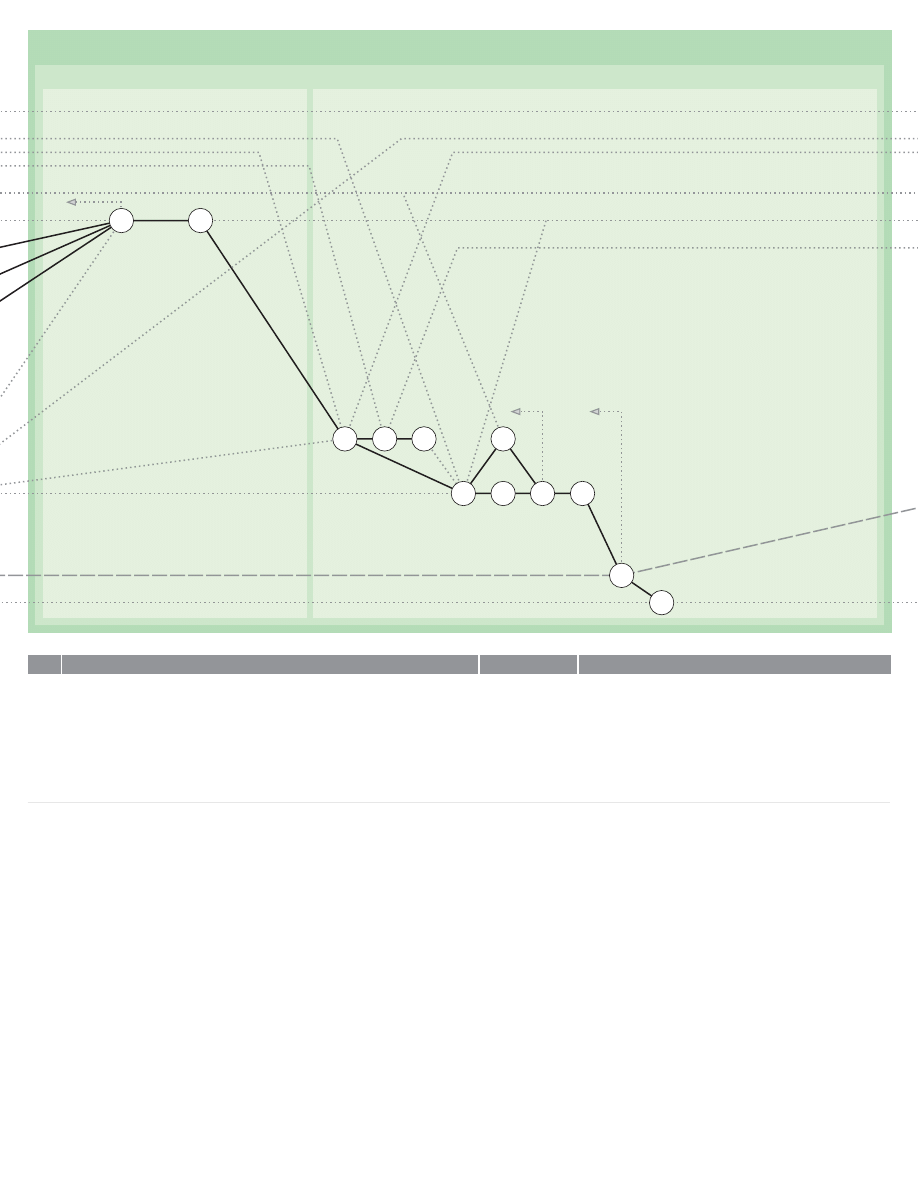
0HASE#ONTINUED
!NALYSIS#ONTINUED
0REPARE0ERFORMANCE3PECIFICATION#ONTINUED
2EAPPRAISE0ROGRAM!ND%STIMATE
3ELECT!LL4HE3UBPROBLEMS,ISTED5NDER!ND7HICH3TAND(IGH/N4HE2ANK
/RDERED,IST!ND2EEXAMINE4HEM!CCORDING4O3ELECTION2EEXAMINE!SSIGNED
6ALUES!ND3IMPLIFYING!SSUMPTIONS!T
2EITERATE&ROM!S.ECESSARY)F4OO-ANY)NCOMPATIBILITIES2EMAIN2EITERATE3ECTIONS
!ND3EEKING%ASEMENTS
7HEN!LL0ROBLEMS!BOUT%NDS(AVE"EEN2ESOLVED/R!S-ANY/F4HEM!S3EEMS
0RACTICABLE!SSEMBLE!LL4HEIR3OLUTIONS)NTO!0ERFORMANCE/R$ESIGN3PECIFICATION
2ANKED3UBSTANTIALLY)N!CCORDANCE7ITH
,IST!NY2EMAINING)NTRACTABLE0ROBLEMS!BOUT%NDS&OR2EFERENCE4O#LIENT!NDOR&OR
2ESOLUTION!S#REATIVE0ROBLEMS
2EAPPRAISE0ROGRAM!ND%STIMATE
)N4HE,IGHT/F!ND2ESTATE4HE0ROBLEM3ET/UT)N
2EAPPRAISE4HE#RUCIAL)SSUES3ET/UT)N
2EAPPRAISE!ND)F.ECESSARY2EFORMULATE!#OURSE/F!CTION0ERVIOUSLY3ET/UT)N
7HERE2EQUIRED0REPARE!2EPORT/N4HE/VERALL0ROBLEMS!BOUT%NDS2EFERRING4O
2EAPPRAISE0ROGRAM!ND4IMETABLE
2EAPPRAISE/FFICE7ORKLOAD!ND0ROJECT&ACILITIES
&ORMULATE$RAFT2EVISED0ROPOSAL!ND%STIMATE
7ITH0ERFORMANCE3PECIFICATION&OR!PPROVAL!ND2EPORT/N/VERALL0ROBLEM!ND%NDS
7HERE.ECESSARY
#HECK!ND!PPROVE$RAFT0ROPOSAL!ND%STIMATE
)F.ECESSARY2EITERATE&ROM5NTIL!3ATISFACTORY0ROPOSAL)S$RAFTED
0REPARE!ND$ISPATCH&AIR#OPY/F0ROPOSAL!ND%STIMATE
"RING&ILES!ND0ROGRESS-ACHINERY5P4O$ATE
2EITERATE3ECTION5NTIL!GREEMENT)S2EACHED4O#ARRY/UT0HASE0REPARE/UTLINE
$ESIGN0ROPOSALS/R0ROJECT)S4ERMINATED
7HERE3UITABLE0HASE$EVELOP0ROTOTYPE$ESIGNS!NDOR0HASE0REPARE!ND
%XECUTE6ALIDATION3TUDIES-AY!LSO"E#OMMISSIONED!T4HE3AME4IME!S0HASE
#RITICAL0ROBLEMS2EEXAMINED
0ERFORMANCE3PECIFICATION2EADY
2EMAINING)NTRACTABLE0ROBLEMS!BOUT%NDS,ISTED
0ROBLEM2ESTATEMENT2EADY
2EAPPRAISED#RUCIAL)SSUES,ISTED
#OURSE/F!CTION2EFORMULATED
2EPORT/N0ROBLEM!BOUT%NDS2EADY
0ROGRAM!ND4IMETABLE2EAPPRAISED
7ORKLOAD!ND&ACILITIES2EAPPRAISED
$RAFT2EVISED0ROPOSAL0ERFORMANCE3PECIFICATION!ND
%STIMATE2EADY
$RAFT0ROPOSAL!ND%STIMATE$ISPATCHED
0ROPOSAL!ND%STIMATE$ISPATCHED
&ILES!ND0ROGRESS-ACHINERY5P4O$ATE
!CTIVITY
!CTIVITY.O
%VENT
)TEM
104
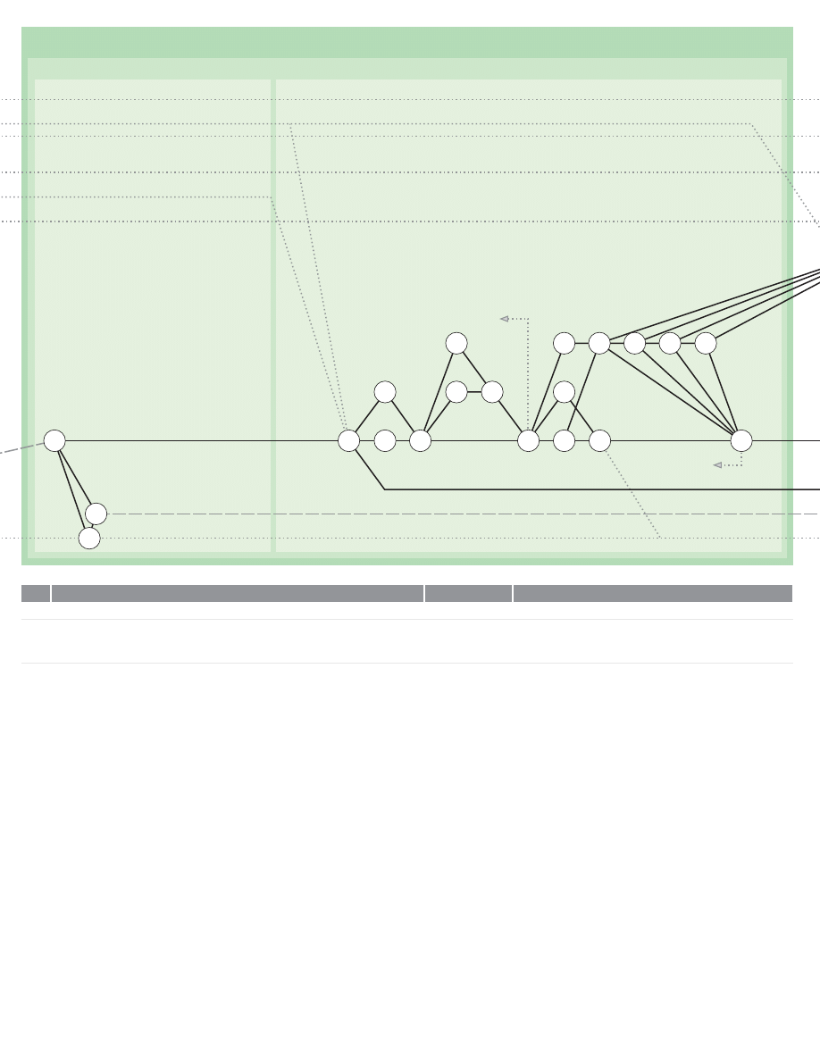
0HASE
3YNTHESIS
2ECEIVE)NSTRUCTIONS
2ESOLVE2EMAINING0ROBLEMS!BOUT%NDS
N
N
N
N
N
N
N
N
N
N
N
N
N
N
N
N
3YNTHESIS
2ECEIVE)NSTRUCTIONS
3END!CKNOWLEDGMENT
"RING&ILES!ND0ROGRESS-ACHINERY5P4O$ATE
2ESOLVE2EMAINING0ROBLEMS!ND%NDS.OTE4HAT)N'ENERAL3OLUTIONS4O0ROBLEMS
!BOUT%NDS7ILL0OSE0ROBLEMS!BOUT-EANS
2EAPPRAISE4HE0ERFORMANCE3PECIFICATION0REPARED5NDER!ND4HE,IST/F)NTRACTABLE
0ROBLEMS!BOUT%NDS0REPARED5NDER!ND0REPARE!.EW,IST/F5NRESOLVED0ROBLEMS
!BOUT%NDS
&OR%ACH0ROBLEM)N4HE,IST0REPARE5NDER,IST4HE&ACTORS)N4HE0ROBLEM
)DENTIFY4HE'OALS4O"E!CHIEVED!ND4HE#ONSTRAINTS/R#ONDITIONS4O"E3ATISFIED
%STABLISH4HE#ONNECTIONS"ETWEEN4HE&ACTORS/R4HE'OALS!ND#ONSTRAINTS/R#ONDITIONS
)DENTIFY3IMILAR/R!NALOGOUS0ROBLEMS)N0RIOR%XPERIENCE
)DENTIFY3IMILAR/R!NALOGOUS0ROBLEMS(ANDLED%LSEWHERE
#ATALOG4HE0ROPERTIES/F4HE!NALOGOUS0ROBLEMS!ND2EEXPRESS%ACH7ITHIN!
#OMMON&ORMAT
2EEXPRESS0RESENT3UBPROBLEM7ITHIN4HE&ORMAT$EVELOPED5NDER
)DENTIFY4HOSE&ACTORS)N4HE3UBPROBLEM&OR7HICH4HE$ATA6ALUES-AY"E6OLUNTARILY
&IXED"Y4HE$ESIGNER
)DENTIFY4HOSE&ACTORS)N4HE3UBPROBLEM&OR7HICH4HE$ATA6ALUES!RE&IXED"Y
%XTERNAL)NFLUENCES
)DENTIFY4HOSE&ACTORS7HERE4HE$ATA!RE$EPENDENT6ARIABLES&OR%XAMPLE7HERE4HE
$ATA!RE4HE3OLUTIONS4O/THER3UBPROBLEMS)F.ECESSARY3USPEND7ORK/N4HIS
0ROBLEM!ND3ELECT!NOTHER!T3O4HAT3UBPROBLEMS!RE$EALT7ITH)N4HE2IGHT/RDER
#OLLECT.ECESSARY$ATA%ITHER%XTRACT$ATA&ROM2ECORD3YSTEM/R!DD&RESH$ATA
7HERE3UFFICIENT0RECISE$ATA)S.OT!VAILABLE0OSTULATE3IMPLIFYING!SSUMPTIONS/R!SSIGN
6ALUES"Y0LAUSIBLE2EASONING
7HERE.OT0RACTICAL3OLUTION%MERGES6ARY/NE/F4HE6OLUNTARILY!SSIGNED6ALUES!NDOR
!SSUMPTIONS3EE!ND!ND3EEK%ASEMENTS
7HERE4HIS&AILS2EAPPRAISE#ONSTRAINTS3EE!ND3EEK%ASEMENTS
)N4HE,AST2ESORT2EAPPRAISE'OALS3EE!ND3EEK6ARIATION
2ESOLVE0ROBLEM$ELINEATING-AXIMUM&IELD/F&EASIBLE3OLUTIONS
#OMMISSION2ECEIVED4O%XECUTE0HASE
!CKNOWLEDGMENT$ISPATCHED
&ILES!ND0ROGRESS-ACHINERY5P4O$ATE
2EVISED,IST/F5NRESOLVED0ROBLEMS!BOUT%NDS2EADY
,IST/F&ACTORS)N3UBPROBLEM2EADY
'OALS!ND#ONSTRAINTS/R#ONDITIONS&OR
3UBPROBLEMS)DENTIFIED
#ONNECTIONS"ETWEEN&ACTORS%STABLISHED
!NALOGOUS0ROBLEMS)N0RIOR%XPERIENCE)DENTIFIED
!NALOGOUS0ROBLEMS(ANDLED%LSEWHERE)DENTIFIED
!NALYSIS/F!NALOGOUS0ROBLEMS#OMPLETE
2EEXPRESSION/F3UBPROBLEM7ITHIN#OMMON
&ORMAT#OMPLETE
&ACTORS7HERE$ATA6ALUES!RE6OLUNTARILY!SSIGNABLE
)DENTIFIED
&ACTORS7HERE$ATA6ALUES!RE%XTERNALLY&IXED)DENTIFIED
&ACTORS7HERE$ATA!RE$EPENDENT6ARIABLES)DENTIFIED
.ECESSARY$ATA2EADY
3IMPLIFYING!SSUMPTIONS0OSTULATED!NDOR$ATA
6ALUES!SSIGNED
.O3OLUTION!SSIGNED6ALUES!NDOR3IMPLIFYING
!SSUMPTIONS6ARIED
.O3OLUTION#ONSTRAINTS/R#ONDITIONS%ASED
.O3OLUTION'OALS6ARIED
3OLUTION4O3UBPROBLEM2EADY
!CTIVITY
!CTIVITY.O
%VENT
)TEM
105
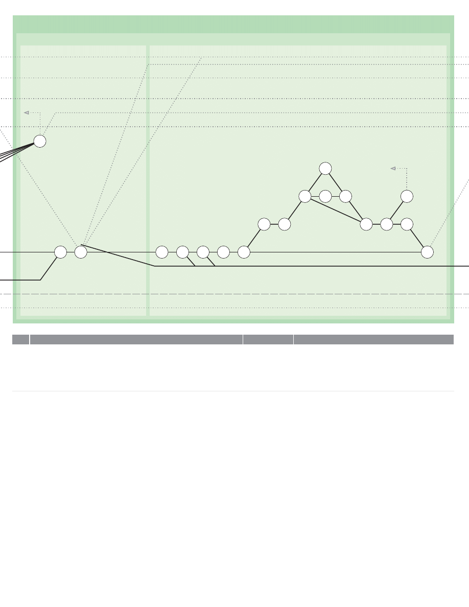
0HASE#ONTINUED
3YNTHESIS#ONTINUED
2ESOLVE2EMAINING0ROBLEMS!BOUT%NDS#ONTINUED
0OSTULATE-EANS&OR2ECONCILING$IVERGENT$ESIDERATA)N0ERFORMANCE3PECIFICATION
N
N
N
N
N
N
N
N
N
N
N
N
)F!6ARIATION/R!SSUMPTION(AS"EEN-ADE5NDER!ND!3OLUTION(AS%MERGED
2EFER4O3OURCE!ND#HECK0RIMA&ACIE!CCEPTABILITY/F6ARIATION/R!SSUMPTION3EE!LSO
6ALIDATION3TUDIES3ECTION7HERE.ECESSARY2EITERATE&ROM
2EITERATE&ROM5NTIL!LL/UTSTANDING0ROBLEMS!BOUT%NDS,ISTED5NDER!RE
2ESOLVED
5NITE3OLUTIONS0REPARED5NDER7ITH0ERFORMANCE3PECIFICATION0REPARED5NDER
4O&ORM!2EVISED3PECIFICATION
0OSTULATE-EANS&OR2ECONCILING$IVERGENT$ESIDERATA)N0ERFORMANCE3PECIFICATION
%XAMINE4HE!UGMENTED0ERFORMANCE3PECIFICATION0REPARED5NDER!ND)DENTIFY
!ND'ROUP4HOSE$ESIDERATA7HICH!PPEAR4O"E)NTERRELATED
,IST4HE'ROUPS/F)NTERRELATED$ESIDERATA
&ROM4HE,IST0REPARED5NDER3ELECT4HOSE'ROUPS#ONTAINING$ESIDERATA7HICH
!PPEAR4O"E$IVERGENT/R#ONTRADICTORY
&OR%ACH'ROUP3ELECTED5NDER2EEXPRESS4HE$ESIDERATA!S4HE'OALS!ND
#ONSTRAINTS/R#ONDITIONS&OR/NE/R-ORE0ROBLEMS!BOUT-EANS
,IST4HE0ROBLEMS!BOUT-EANS4HUS)DENTIFIED
&OR%ACH0ROBLEM!BOUT-EANS,ISTED5NDER,IST4HE&ACTORS)N4HE0ROBLEM
)DENTIFY'OALS!ND#ONSTRAINTS/R#ONDITIONS)N4HE3UBPROBLEM
%STABLISH4HE#ONNECTIONS"ETWEEN4HE&ACTORS'OALS!ND#ONSTRAINTS/R
#ONDITIONS
)DENTIFY3IMILAR/R!NALOGOUS0ROBLEMS)N0RIOR%XPERIENCE
)DENTIFY3IMILAR/R!NALOGOUS0ROBLEMS(ANDLED%LSEWHERE
#ATALOG4HE0ROPERTIES/F4HE.EAREST!NALOGOUS0ROBLEMS!ND4HE%LEMENTS/F4HEIR
2ESPECTIVE3OLUTIONS!ND0REPARE!0ROBLEM%LEMENTPROBLEM3OLUTION-ATRIX
2EEXPRESS4HE0RESENT0ROBLEM7ITHIN4HE3AME-ATRIX
%XPLORE#OMBINATIONS/F3OLUTION%LEMENTS
3ELECT!0ROMISING#OMBINATION/F3OLUTION%LEMENTS!S!(YPOTHESIS&OR$EVELOPMENT
7HERE.O0ROMISING(YPOTHESIS%MERGES2EITERATE&ROM)N7IDER&IELDS
2EITERATE&ROM5NTIL!LL0ROBLEMS!BOUT-EANS!RISING&ROM$IVERGENT$ESIDERATA)N4HE
0ERFORMANCE3PECIFICATION!RE2ESOLVED
!SSEMBLE(YPOTHETICAL3OLUTIONS
0RIMA&ACIE6ALIDATION/F!SSUMPTIONS!ND6ARIATIONS
#OMPLETE
!LL0ROBLEMS!BOUT%NDS2ESOLVED
2EVISED0ERFORMANCE3PECIFICATION2EADY
)NTERRELATED$ESIDERATA)DENTIFIED)NTERACTION-ATRIX
,IST/F)NTERRELATED$ESIDERATA2EADY
'ROUPS#ONTAINING$IVERGENT$ESIDERATA)DENTIFIED
$IVERGENT$ESIDERATA2EEXPRESSED!S'OALS
,IST/F0ROBLEMS!BOUT-EANS2EADY
,IST/F&ACTORS)N4HE3UBPROBLEM2EADY
,IST/F'OALS!ND#ONSTRAINTS/R#ONDITIONS2EAD
#ONNECTION"ETWEEN&ACTORS!ND4HE'OALS!ND
#ONSTRAINTS/R#ONDITIONS%STABLISHED
!NALOGOUS0ROBLEMS)N0RIOR%XPERIENCE)DENTIFIED
!NALOGOUS0ROBLEMS(ANDLED%LSEWHERE)DENTIFIED
0ROBLEM%LEMENTSOLUTION-ATRIX2EADY
2EEXPRESSION/F3UBPROBLEM7ITH3AME-ATRIX#OMPLETE
%XPLORATION/F#OMBINATIONS/F3OLUTION%LEMENTS#OMPLETE
(YPOTHESIS3ELECTED
.O(YPOTHESIS
3OLUTIONSINPRINCIPLE!SSEMBLED
!CTIVITY
!CTIVITY.O
%VENT
)TEM
106
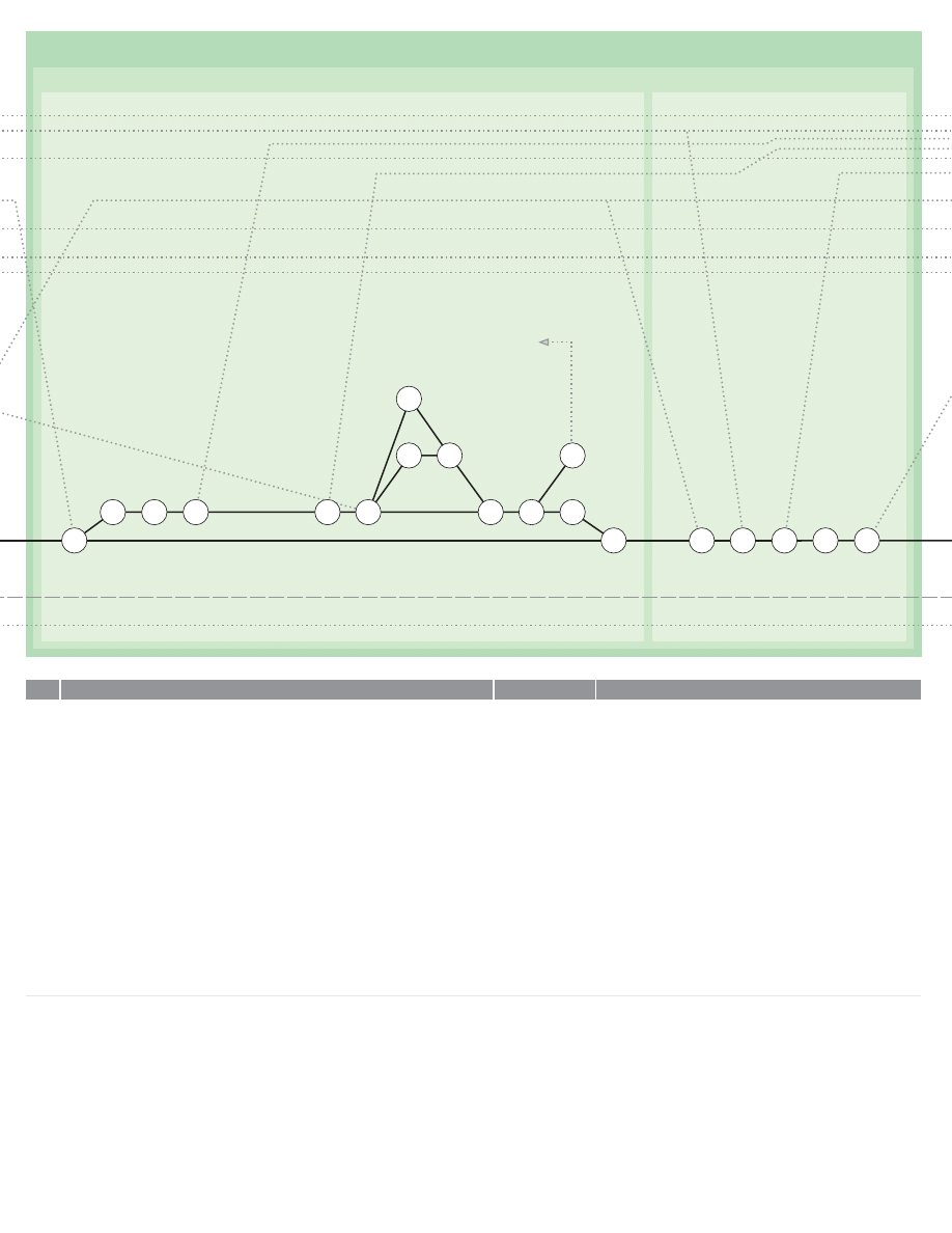
0HASE#ONTINUED
3YNTHESIS#ONTINUED
$EVELOP3OLUTIONS)N0RINCIPLE4O0ROBLEMS!BOUT-EANS!RISING&ROM0ERFORMANCE3PECIFICATION
0OSTULATE/UTLINE/VERALL3OLUTIONS
OR
N
N
N
N
N
N
N
N
N
N
N
N
N
$EVELOP3OLUTIONS)N0RINCIPLE4O0ROBLEMS!BOUT-EANS!RISING&ROM0ERFORMANCE
3PECIFICATION
2EFERRING4O4HE0ERFORMANCE3PECIFICATION0REPARED5NDER4HE,IST/F'ROUPS/F
)NTERRELATED$ESIDERATA0REPARED5NDER,IST4HOSE'ROUPS!ND3INGLE$ESIDERATA.OT9ET
(ANDLED!DD!NY0ROBLEM!BOUT-EANS2EMAINING&ROM4HOSE5NDER
&OR%ACH)TEM,ISTED5NDER2EEXPRESS4HE'OALS!ND#ONSTRAINTS&OR/NE/R-ORE
0ROBLEMS!BOUT-EANS
,IST4HE0ROBLEMS!BOUT-EANS4HUS)DENTIFIED
&OR%ACH0ROBLEM!BOUT-EANS,ISTED5NDER,IST4HE&ACTORS)N4HE0ROBLEM
)DENTIFY'OALS!ND#ONSTRAINTS/R#ONDITIONS)N4HE3UBPROBLEM
%STABLISH4HE#ONNECTIONS"ETWEEN4HE&ACTORS'OALS!ND#ONSTRAINTS/R
#ONDITIONS
)DENTIFY3IMILAR/R!NALOGOUS0ROBLEMS)N0RIOR%XPERIENCE
)DENTIFY3IMILAR/R!NALOGOUS0ROBLEMS(ANDLED%LSEWHERE
#ATALOG4HE0ROPERTIES/F4HE.EAREST!NALOGOUS0ROBLEMS!ND4HE%LEMENTS/F4HEIR
2ESPECTIVE3OLUTIONS!ND0REPARE!0ROBLEM%LEMENTPROBLEM3OLUTION-ATRIX
2EEXPRESS4HE0RESENT0ROBLEM7ITHIN4HE3AME-ATRIX
%XPLORE#OMBINATIONS/F3OLUTION%LEMENTS
3ELECT!0ROMISING#OMBINATION/F3OLUTION%LEMENTS!S!(YPOTHESIS&OR$EVELOPMENT
7HERE.OT0ROMISING(YPOTHESIS&OR$EVELOPMENT%MERGES2EITERATE&ROM)N7IDER&IELD
2EITERATE&ROM5NTIL!LL0ROBLEMS!BOUT-EANS!RISING&ROM$ESIDERATA)N0ERFORMANCE
3PECIFICATION!RE2ESOLVED)N0RINCIPLE
!SSEMBLE(YPOTHETICAL3OLUTIONS
0OSTULATE/UTLINE/VERALL3OLUTIONS
5NITE4HE#OLLECTION/F(YPOTHETICAL3OLUTIONS5NDER7ITH4HOSE5NDER
5SING4HE0ERFORMANCE3PECIFICATION0REPARED5NDER!S!'UIDE4AKE%VERY
#OMBINATION/F0AIRS/F(YPOTHETICAL3OLUTIONS!ND)DENTIFY7HICH)N%ACH0AIR3HOULD
4AKE0RECEDENCE)F4HEY3HOULD,ATER0ROVE4O"E)NCOMPATIBLE
2ANK4HE#OLLECTION/F(YPOTHETICAL3OLUTIONS)N/RDER/F0RECEDENCE
4AKING%VERY#OMBINATION/F0ARIS/F(YPOTHETICAL3OLUTIONS&ROM4HE,IST5NDER
"EGINNING7ITH4HE0AIRS#ONTAINING4HE(IGHEST2ANKED3OLUTIONS!ND)N4HE,IGHT/F
7HATEVER)NFORMATION)S2EADILY!VAILABLE#HECK4HE0LAUSIBILITY/F%ACH0AIRgS0ROVING
4O"E#OMPATIBLE
7HERE0ROBABLE)NCOMPATIBILITIES!RE)DENTIFIED2EITERATE&ROM
,IST/F/UTSTANDING)NTERRELATED$ESIDERATA2EADY
'OALS!ND#ONSTRAINTS&OR0ROBLEMS!BOUT-EANS)DENTIFIED
,IST/F0ROBLEMS!BOUT-EANS2EADY
,IST/F&ACTORS)N4HE3UBPROBLEM2EADY
2EVISED,IST/F'OALS!ND#ONSTRAINTS/R#ONDITIONS2EADY
#ONNECTION"ETWEEN&ACTORS!ND4HE'OALS!ND
#ONSTRAINTS/R#ONDITIONS%STABLISHED
!NALOGOUS0ROBLEMS)N0RIOR%XPERIENCE)DENTIFIED
!NALOGOUS0ROBLEMS(ANDLED%LSEWHERE)DENTIFIED
0ROBLEM%LEMENTSOLUTION-ATRIX2EADY
2EEXPRESSION/F3UBPROBLEM7ITH3AME-ATRIX#OMPLETE
%XPLORATION/F#OMBINATIONS/F3OLUTION%LEMENTS#OMPLETE
(YPOTHESIS3ELECTED
.O(YPOTHESIS
3OLUTIONSINPRINCIPLE!SSEMBLED
#OMBINED#OLLECTION/F(YPOTHETICAL3OLUTIONS2EADY
2ANKING-ATRIX&OR0ROBLEMS!BOUT%NDS2EADY
2ANKED,IST/F(YPOTHETICAL3OLUTIONS2EADY
#OMPATIBILITY3TUDIES#OMPLETE
!CTIVITY
!CTIVITY.O
%VENT
)TEM
107
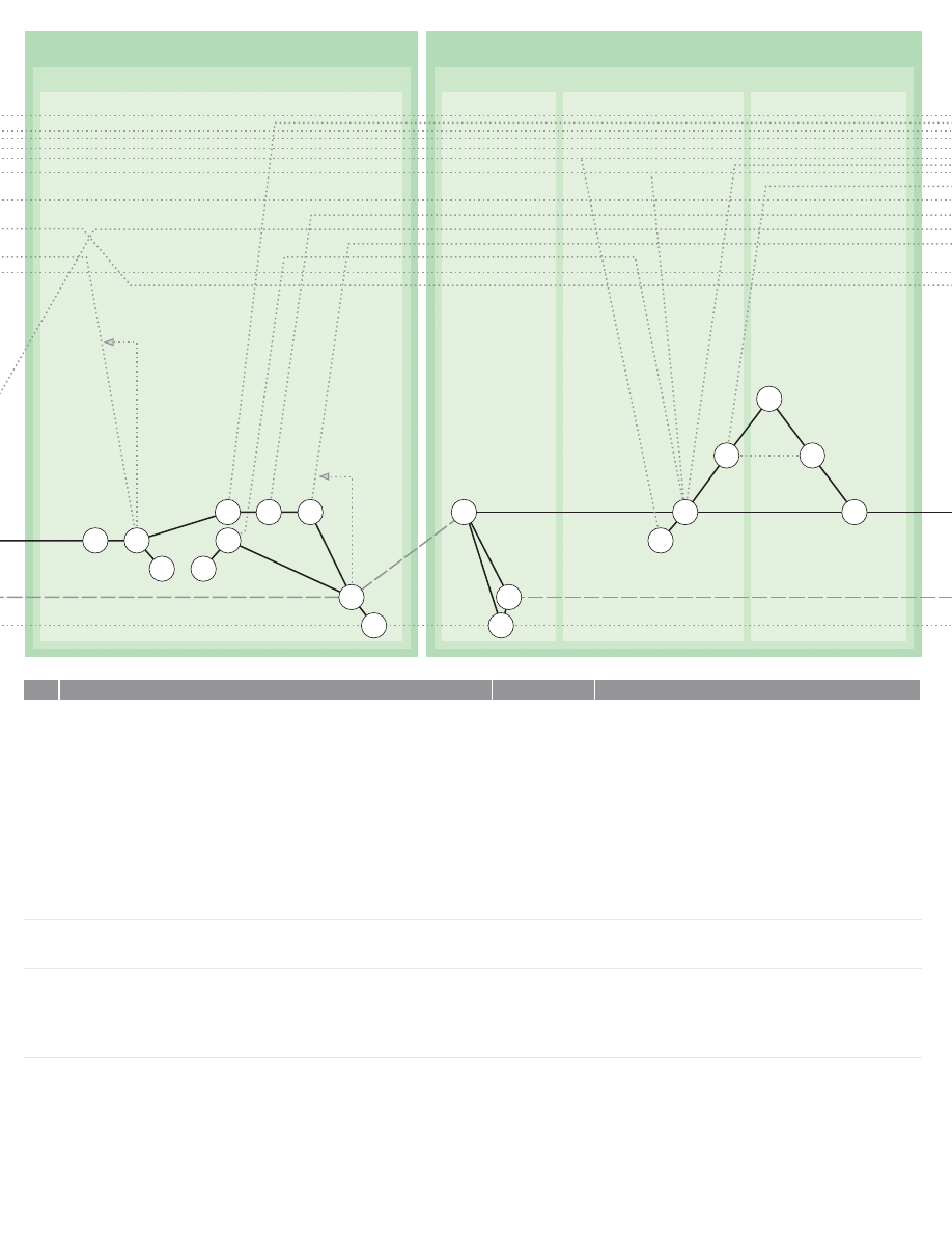
0HASE
$EVELOPMENT
0HASE#ONTINUED
3YNTHESIS#ONTINUED
!SSEMBLE!LL4HE(YPOTHETICAL3OLUTIONS)NTO!3UGGESTED#OMPOSITE/VERALL3OLUTION/R
2ANGE/F3OLUTIONS
2EAPPRAISE4HE0ROPOSED3OLUTIONS)N4HE,IGHT/F4HE0ROBLEM!S3ET/UT)N
2EAPPRAISE4HE0ROPOSED3OLUTIONS)N4HE,IGHT/F#RUCIAL)SSUES3ET/UT)N
7HERE2EQUIRED0REPARE!ND3UBMIT3KETCH$ESIGNS3EE.OTE"ELOW
2EAPPRAISE!ND)F.ECESSARY2EFORMULATE!#OURSE/F!CTION0REVIOUSLY3ET/UT)N
2EAPPRAISE4IMETABLE
2EAPPRAISE&ACILITIES
)F.ECESSARY0REPARE2EVISED0ROPOSALS
"RING&ILES!ND0ROGRESS-ACHINERY5P4O$ATE
.OTE)F3KETCH$ESIGNS-UST"E3UBMITTED&OR!PPROVAL!T4HIS3TAGE3EE#ONTINUE7ITH
3ECTION!ND4HEN4HE7HOLE/F3ECTION&OR4HE3KETCH$ESIGN/NLY2EITERATE4HE7HOLE/F
3ECTION5NTIL!3KETCH$ESIGN)S!PPROVED!ND!#OMMISSION)S2ECEIVED4O%XECUTE0HASE
0ROCEED7ITH3ECTION)N2ESPECT/F4HE&INISHED$ESIGN
$EVELOPMENT
2ECEIVE)NSTRUCTIONS
3END!CKNOWLEDGMENT
"RING&ILES!ND0ROGRESS-ACHINERY5P4O$ATE
$EFINE$ESIGN)DEA
5SING4HE-OST!BSTRACT/R'ENERAL-EDIUM!VAILABLEEG!&ORM/F7ORDS#OMPLETELY
$EFINE4HE%SSENTIAL'ERM/F4HE$ESIGN)DEA
5SING4HE3AME-EDIUM$EFINE4HE-AXIMUM6ARIATION%MBRACEABLE"Y4HE$ESIGN)DEA
)N4HE#ASE/F3KETCH$ESIGNS"EING0REPARED5NDER0ROCEED.OW7ITH3ECTION
)N2ESPECT/F3KETCH$ESIGNS/NLY
%RECT!+EY-ODEL
,IST2ANGE/F-EDIA&OR4HE2EPRESENTATION/F!N%MBODIMENT/F4HE$ESIGN)DEA
3ELECT4HE,EAST!BSTRACT-EDIUM7HICH7ILL%XHAUSTIVELY$ESCRIBE4HE6ARIANTS/F4HE
$ESIGN)DEA3EE
%RECT!+EY-ODEL/F4HE%SSENTIAL$ESIGN)DEA3HOWING!LL)TgS6ARIANTS
#OMPOSITE/VERALL3OLUTIONS2EADY
2EAPPRAISAL)N,IGHT/F/RIGINAL0ROBLEM
2EAPPRAISAL)N,IGHT/F#RUCIAL)SSUES#OMPLETE
3KETCH$ESIGNS2EADY
2EAPPRAISAL!NDOR2EFORMULATION/F#OURSE/F!CTION#OMPLETE
2EAPPRAISAL/F4IMETABLE#OMPLETE
2EAPPRAISAL/F&ACILITIES#OMPLETE
2EVISED0ROPOSALS2EADY
&ILES!ND0ROGRESS-ACHINERY5P4O$ATE
#OMMISSION2ECEIVED4O%XECUTE0HASE
!CKNOWLEDGMENT$ISPATCHED
&ILES!ND0ROGRESS-ACHINERY5P4O$ATE
$EFINITION/F%SSENTIAL'ERM/F$ESIGN)DEA2EADY
$EFINITION/F2ANGE/F6ARIATION%MBRACEABLE"Y$ESIGN
)DEA2EADY
,IST/F!VAILABLE-EDIA2EADY
-EDIUM3ELECTED
+EY-ODEL%RECTED
!CTIVITY
!CTIVITY.O
%VENT
)TEM
0OSTULATE/UTLINE/VERALL3OLUTIONS#ONTINUED
2ECEIVE)NSTRUCTIONS
$EFINE$ESIGN)DEA
%RECT!+EY-ODEL
108
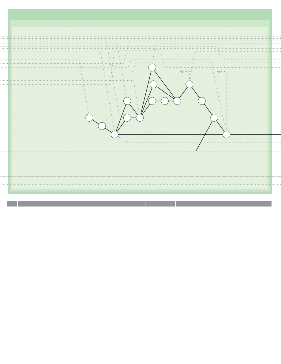
0HASE#ONTINUED
$EVELOPMENT#ONTINUED
N
N
N
N
N
N
N
N
N
N
N
$EVELOP3UBPROBLEM-UTUAL3OLUTIONS
4AKE4HE#OMBINED#OLLECTION/F(YPOTHETICAL3UBPROBLEM3OLUTIONS5NDER!ND)N
4HE,IGHT/F4HE)NFORMATION%MPLOYED)N4HEIR2ESPECTIVE2ESOLUTIONS3EE3ECTION!ND
3ECTION)DENTIFY!LL#OMBINATIONS/F0AIRS/F(YPOTHETICAL3OLUTIONS7HICH!PPEAR4O
)NVOLVE)NTERACTING$EVELOPMENT$ETAILS
,IST4HE)NTERACTING0AIRS4HUS)DENTIFIED
5SING4HE2ANKED,IST/F(YPOTHETICAL3UBPROBLEM3OLUTIONS0REPARED5NDER!S!'UIDE
)DENTIFY!ND0LOT)N4HE&ORM/F!.ETWORK4HE-OST$ESIRABLE3EQUENCE&OR$ETAILED
$EVELOPMENT/F4HE#HAIN/F(YPOTHETICAL3UBPROBLEM3OLUTIONS
3ELECT4HE%ARLIEST5NDEVELOPED(YPOTHESIS)N4HE.ETWORK2EFERRING7HERE.ECESSARY4O
7ORKING0APERS0REPARED5NDER3ECTION!ND,IST4HE&ACTORS)N$EVELOPING4HIS
(YPOTHESIS)NTO!-ATERIAL%MBODIMENT
2EFERRING7HERE.ECESSARY4O7ORKING0APERS5NDER3ECTION)DENTIFY4HE'OALS!ND
#ONSTRAINTS/R#ONDITIONS)N4HE3UBPROBLEM
2EFERRING7HERE.ECESSARY4O7ORKING0APERS0REPARED5NDER3ECTION%STABLISH4HE
#ONNECTIONS"ETWEEN4HE&ACTORS'OALS!ND#ONSTRAINTS/R#ONDITIONS
)DENTIFY4HOSE&ACTORS7HERE4HE$ATA6ALUES-AY"E6OLUNTARILY!SSIGNED"Y4HE$ESIGNER
)DENTIFY4HOSE&ACTORS7HERE4HE$ATA6ALUES!RE&IXED"Y%XTERNAL)NFLUENCES
)DENTIFY4HOSE&ACTORS7HERE4HE$ATA!RE$EPENDENT6ARIABLES&OR%XAMPLE7HERE4HE$ATA
!RE(E3OLUTIONS4O/THER3UBPROBLEMS
)F.ECESSARY2EVISE.ETWORK0REPARED5NDER3O4HAT0ROBLEMS7HICH0ROVIDE$ATA&OR
/THER3UBPROBLEMS!RE$EALT7ITH)N4HE2IGHT/RDER/R3ELECT!NOTHER0ROBLEM!T
#OLLECT.ECESSARY$ATA
7HERE3UFFICIENT!ND3UFFICIENTLY0RECISE$ATA)S!VAILABLE$EVELOP!-ODEL%MBODIMENT
/F4HE(YPOTHETICAL3OLUTION
7HERE3UFFICIENT0RECISE$ATA)S.OT!VAILABLE0OSTULATE3IMPLIFYING!SSUMPTIONS"Y
0LAUSIBLE2EASONING!ND$EVELOP!-ODEL%MBODIMENT/F4HE(YPOTHETICAL3OLUTION
4EST4HE%MBODIMENT&OR&IT7ITHIN4HE&RAMEWORK/F4HE+EY-ODEL
7HERE%MBODIMENT)S&OUND4O"E)MPRACTICABLE2EVISE(YPOTHETICAL3OLUTION"Y
2EITERATING3ECTION&OR4HAT3UBPROBLEM!ND3ECTION&OR4HE%FFECT/F!.EW
(YPOTHESIS/N4HE/VERALL$ESIGN#ONCEPT
2EEXAMINE4HE)NTERACTION-ATRIX0REPARED5NDER!ND4HE.ETWORK0REPARED5NDER
2EVISE.ETWORK!S.ECESSARY!ND3ELECT!NOTHER3UBPROBLEM
)NTERACTION-ATRIX2EADY
,IST/F)NTERACTING0AIRS/F(YPOTHETICAL
3UBPROBLEM3OLUTIONS2EADY
,IST/F&ACTORS)N3UBPROBLEM2EADY
,IST/F'OALS!ND#ONSTRAINTS/R#ONDITIONS2EADY
#ONNECTIONS"ETWEEN&ACTORS%STABLISHED
&ACTORS7HERE$ATA6ALUES!RE6OLUNTARILY!SSIGNABLE)DENTIFIED
&ACTORS7HERE$ATA6ALUES!RE&IXED"Y%XTERNAL)NFLUENCES)DENTIFIED
&ACTORS7HERE$ATA6ALUES!RE$EPENDENT6ARIABLES)DENTIFIED
2EVISED.ETWORK2EADY
.ECESSARY$ATA2EADY
3IMPLIFYING!SSUMPTIONS0OSTULATED
-ATERIAL%MBODIMENT2EADY
4EST/F3UBPROBLEM3OLUTION%MBODIMENT7ITH+EY
-ODEL#OMPLETE
!LL(YPOTHETICAL3UBPROBLEM3OLUTIONS%MBODIED
!CTIVITY
!CTIVITY.O
%VENT
)TEM
$EVELOP3UBPROBLEM-UTUAL3OLUTIONS
109
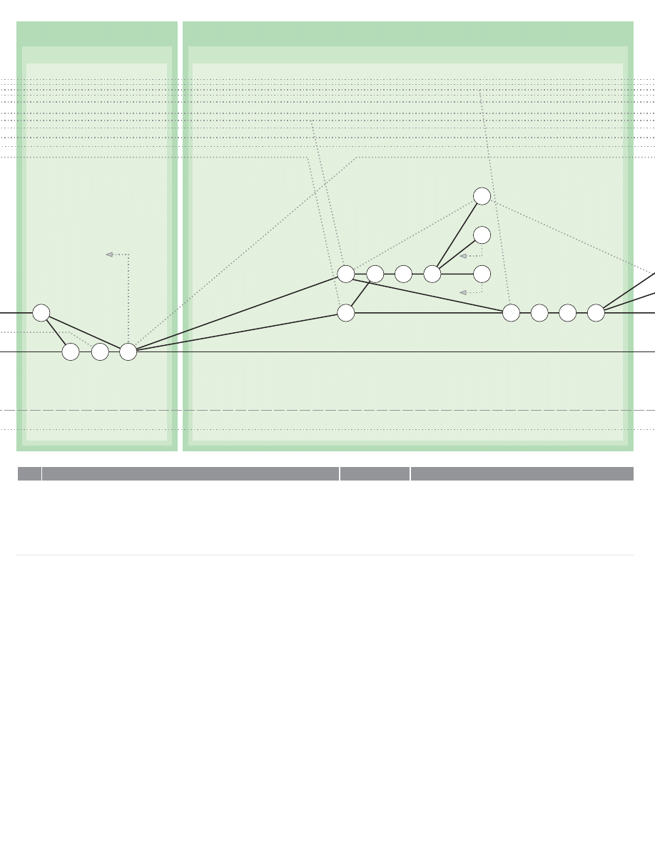
0HASE#ONTINUED
$EVELOPMENT#ONTINUED
N
N
N
N
N
N
N
N
N
$EVELOP/VERALL3OLUTIONS
5NITE-ODEL3UBPROBLEM%MBODIMENTS)NTO/NE/R-ORE-ODEL/VERALL3OLUTIONS
)DENTIFY5NDEVELOPED!REAS)N4HE$ESIGN
2EEXPRESS!S!3EQUENCE/F!DDITIONAL0ROBLEMS&OR#OMPLETION
$EVELOP%ACH0ROBLEM5NDER"Y2EITERATING&ROM
2EITERATE3ECTION5NTIL/NE/R-ORE/VERALL3OLUTIONS!RE&ULLY$EVELOPED
$EVELOP%ACH0ROBLEM5NDER"Y2EITERATING&ROM
2EITERATE3ECTION5NTIL/NE/R-ORE/VERALL3OLUTIONS!RE&ULLY$EVELOPED
6ALIDATE(YPOTHESES
3ELECT!ND,IST4HOSE0ROBLEMS!BOUT%NDS7HERE$ATA6ALUES7ERE6OLUNTARILY!SSIGNED
3EE!ND
3ELECT!ND,IST4HOSE0ROBLEMS!BOUT%NDS7HERE3IMPLIFYING!SSUMPTIONS7ERE-ADE3EE
!ND
&OR%ACH0ROBLEM,ISTED5NDER/R&ORMULATE(YPOTHESES#ALCULATED4O&ACILITATE
4HE6ALIDATION/F4HE3OLUTION4O4HE0ROBLEM3EE!ND
&OR%ACH(YPOTHESIS5NDER$ESIGN!N%XPERIMENT4O4EST4HE(YPOTHESIS!ND6ALIDATE
4HE3OLUTION3EE.OTE"ELOW
#ONDUCT6ALIDATION%XPERIMENT/R3TUDY!S0LANNED5NDER
7HERE4HE%XPERIMENT/R3TUDY3HOWS4HAT4HE3OLUTION4O4HE0ROBLEM!BOUT%NDS)S
)NVALID3EE4HEN2EWORK4HE0ROBLEM!BOUT%NDS!ND!LL)TgS2AMIFICATIONS&ROM
7HERE4HE%XPERIMENT/R3TUDY)S)NCONCLUSIVE2EITERATE&ROM
7HERE4HE%XPERIMENT/R3TUDY)NDICATES4HAT4HE3OLUTION4O4HE0ROBLEM!BOUT%NDS)S
3UPPORTED2EITERATE&ROM5NTIL0ROBLEMS,ISTED5NDER!ND!RE6ALIDATED
)DENTIFY!ND,IST4HOSE3TATEMENTS)N4HE0ERFORMANCE3PECIFICATION3EE7HICH(AVE
.OT"EEN%XAMINED5NDER
.OTE7HERE.ECESSARY4HE0ROBLEM/F$ESIGNING!N%XPERIMENT#AN"E(ANDLED"Y4HE
0ROCEDURES3ET/UT)N3ECTION!ND3ECTION4HESE0ROCEDURES)NCLUDE!PPRAISING4HE
3IGNIFICANCE/F4HE0ROBLEM5NDER)NVESTIGATION!ND4HE!MOUNT/F%FFORT7HICH#AN"E
$EVOTED4O)TgS3OLUTION
&OR%ACH3TATEMENT,ISTED5NDER&ORMULATE(YPOTHESES#ALCULATED4O&ACILITATE
6ALIDATION/F4HE3TATEMENT
&OR%ACH(YPOTHESIS5NDER$ESIGN!N%XPERIMENT4O4EST4HE(YPOTHESIS!ND6ALIDATE
4HE3TATEMENT3EE.OTE/N0AGE
#ONDUCT6ALIDATION%XPERIMENT/R3TUDY!S0LANNED5NDER
-ODEL/VERALL3OLUTION2EADY
5NDERDEVELOPED!REA)DENTIFIED
.EW.ETWORKS2EADY
/VERALL3OLUTION2EADY
/VERALL3OLUTION2EADY
,IST/F0ROBLEMS!BOUT%NDS#ONTAINING
6OLUNTARILY!SSIGNED6ALUES2EADY
,IST/F0ROBLEMS!BOUT%NDS#ONTAINING3IMPLIFYING
!SSUMPTIONS2EADY
(YPOTHESES2EADY
$ESIGN&OR%XPERIMENT/R4EST2EADY
%XPERIMENT/R3TUDY#OMPLETE
3OLUTION4O0ROBLEM!BOUT%NDS3HOWN4O"E)NVALID
2ESULT/F%XPERIMENT/R3TUDY)NCONCLUSIVE
!LL3OLUTIONS4O0ROBLEMS!BOUT%NDS#ONTAINING
!SSUMPTIONS.OW6ALIDATED
,IST/F5NTESTED3TATEMENTS)N0ERFORMANCE
3PECIFICATION2EADY
(YPOTHESIS&ORMULATED
$ESIGN&OR%XPERIMENT/R3TUDY2EADY
%XPERIMENT/R3TUDY#OMPLETE
!CTIVITY
!CTIVITY.O
%VENT
)TEM
$EVELOP/VERALL3OLUTIONS
0HASE
$EVELOPMENT#ONTINUED
6ALIDATE(YPOTHESES
110
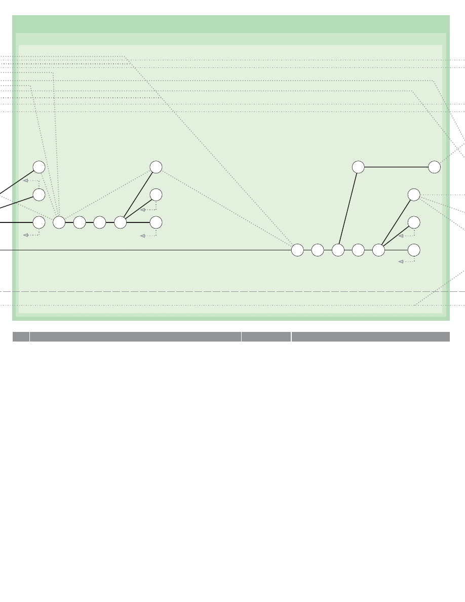
0HASE#ONTINUED
$EVELOPMENT#ONTINUED
6ALIDATE(YPOTHESES#ONTINUED
N
N
N
N
N
N
N
N
N
N
N
N
N
N
7HERE4HE%XPERIMENT/R3TUDY3HOWS4HAT4HE3TATEMENT)N4HE3PECIFICATION)S)NVALID4HEN
2EWORK4HE0ROBLEMS!BOUT%NDS%MBODIED)N4HE3TATEMENT!ND!LL4HEIR2AMIFICATIONS
&ROM
7HERE4HE%XPERIMENT/R3TUDY)S)NCONCLUSIVE2EITERATE&ROM
7HERE4HE%XPERIMENT/R3TUDY)NDICATES4HAT4HE3PECIFICATION3TATEMENT)S3UPPORTED
2EITERATE&ROM5NTIL!LL3TATEMENTS)N4HE0ERFORMANCE3PECIFICATION!RE6ALIDATED
)DENTIFY!ND,IST4HOSE$ESIGN$ETAILS7HERE$ATA6ALUES7ERE6OLUNTARILY!SSIGNED"Y4HE
$ESIGNER3EE!ND7HERE3IMPLIFYING!SSUMPTIONS7ERE-ADE3EE
&OR%ACH$ETAIL5NDER&ORMULATE(YPOTHESES4O&ACILITATE6ALIDATION/F4HE$ETAIL
&OR%ACH(YPOTHESIS5NDER$ESIGN!N%XPERIMENT4O4EST4HE(YPOTHESIS!ND6ALIDATE
4HE$ETAIL3EE.OTE!FTER
#ONDUCT6ALIDATION%XPERIMENT/R3TUDY!S0LANNED5NDER
7HERE4HE%XPERIMENT/R3TUDY3HOWS4HAT4HE$ESIGN$ETAIL)S)NVALID4HEN2EWORK4HE
$ETAIL$EVELOPMENT&ROM
7HERE4HE%XPERIMENT/R3TUDY)S)NCONCLUSIVE2EITERATE&ROM
7HERE4HE%XPERIMENT/R3TUDY)NDICATES4HAT4HE$ESIGN$ETAIL)S3UPPORTED2EITERATE&ROM
5NTIL!LL$ESIGN$ETAILS"ASED5P/N6OLUNTARILY!SSIGNED$ATA!NDOR3IMPLIFYING
!SSUMPTIONS!RE6ALIDATED
4AKING4HE'OALS)DENTIFIED5NDER3ECTION!ND4OGETHER7ITH4HE#ONSTRAINTS,ISTED
5NDER3ECTION!ND4HE0ERFORMANCE3PECIFICATION3ET/UT5NDER&ORMULATE
(YPOTHESES#ALCULATED4O&ACILITATE6ALIDATION/F4HE/VERALL$ESIGNS5NDER
&OR%ACH(YPOTHESIS5NDER$EVISE!N%XPERIMENT4O4EST4HE(YPOTHESIS!ND
6ALIDATE4HE$ESIGN3EE.OTE!FTER
!SSEMBLE4HE#OLLECTION/F0ROPOSED%XPERIMENTS/R3TUDIES0REPARED5NDER
)NTO!6ALIDATION0ROGRAM
$ISTINGUISH"ETWEEN6ALIDATION%XPERIMENTS/R3TUDIES4O"E#ARRIED/UT"EFORE
#OMMUNICATION/F4HE&INAL$ESIGN3OLUTIONS!ND4HOSE7HICH-UST"E#ARRIED/UT/N
-ANUFACTURED-ODELS/R0ROTOTYPES
3ELECT!N!PPROPRIATE6ALIDATION%XPERIMENT/R3TUDY&ROM4HE,IST/F4HOSE7HICH!RE4O"E
#ARRIED/UT"EFORE#OMMUNICATION/F4HE&INAL$ESIGN3OLUTIONS!ND#ONDUCT%XPERIMENT
7HERE4HE%XPERIMENT/R3TUDY3HOWS4HAT4HE$ESIGN)S)NVALID4HEN2EWORK&ROM
7HERE4HE%XPERIMENT/R3TUDY)NDICATES4HAT4HE$ESIGN)S3UPPORTED2EITERATE&ROM
7HERE4HE$ESIGN)S3UPPORTED2EITERATE&ROM5NTIL!LL3TUDIES4O"E#ARRIED/UT
"EFORE#OMMUNICATION/F4HE&INAL$ESIGN3OLUTIONS!RE#OMPLETE
0REPARE!2EPORT/N4HOSE6ALIDATION%XPERIMENTS/R3TUDIES7HICH!RE4O"E#ARRIED/UT/N
-ODELS/R0ROTOTYPES
3PECIFICATION3TATEMENT3HOWN4O"E)NVALID
%XPERIMENT/R3TUDY)NCONCLUSIVE
!LL3PECIFICATION3TATEMENTS6ALIDATED
,IST/F$ESIGN$ETAILS"ASED/N!SSUMPTIONS2EADY
(YPOTHESES&ORMULATED
$ESIGN&OR%XPERIMENT/R3TUDY2EADY
%XPERIMENT/R3TUDY#OMPLETE
$ESIGN$ETAIL3HOWN4O"E)NVALID
%XPERIMENT/R3TUDY)NCONCLUSIVE
!LL$ESIGN$ETAILS"ASED5PON!SSUMPTIONS.OW
6ALIDATED
(YPOTHESES&ORMULATED
$ESIGN&OR%XPERIMENT/R3TUDY2EADY
6ALIDATION0ROGRAM2EADY
3TUDIES4O"E#ARRIED/UT"EFORE#OMMUNICATION/F
4HE&INAL$ESIGN3OLUTIONS)DENTIFIED
3TUDIES4O"E#ARRIED/UT/N0ROTOTYPES)DENTIFIED
%XPERIMENT/R3TUDY#OMPLETE
$ESIGN3HOWN4O"E)NVALID
%XPERIMENT/R3TUDY)NCONCLUSIVE
!LL6ALIDATION3TUDIES4O"E#ARRIED/UT"EFORE
#OMMUNICATION/F4HE$ESIGN#OMPLETE
2EPORT/N6ALIDATION3TUDIES4O"E#ARRIED/UT/N
-ANUFACTURED-ODELS/R0ROTOTYPES.OW2EADY
!CTIVITY
!CTIVITY.O
%VENT
)TEM
111
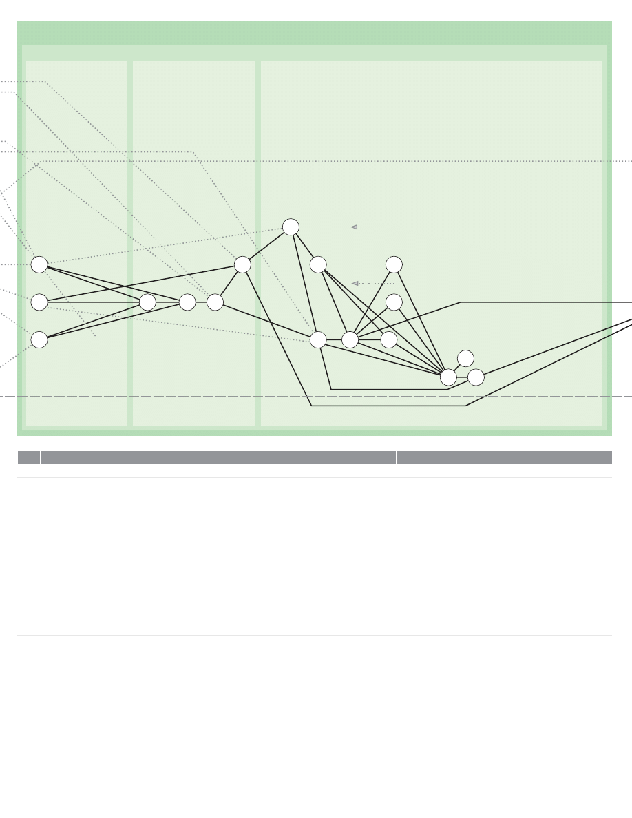
0HASE
#OMMUNICATION
$EFINE#OMMUNICATION.EEDS
3ELECT#OMMUNICATION-EDIUM
0REPARE#OMMUNICATION
N
N
N
N
#OMMUNICATION
$EFINE#OMMUNICATION.EEDS
2EFERRING4O)NSTRUCTIONS3EE!ND!NY3UBSEQUENT!MENDMENTS!T
!NDOR$ETERMINE!DDRESSEE!ND#HANNEL&OR#OMMUNICATION/F$ESIGN
3IMILARLY2EFERRING4O)NSTRUCTIONS!ND!LSO4O#OURSE/F!CTION!DOPTED3EE!ND
3UBSEQUENT!MENDMENTS!T!ND$ETERMINE7HETHER4HE'ENERAL
3PIRIT4HE'EOMETRY!ND0ERFORMANCE/R4HE$ETAILED#ONSTRUCTION/F4HE$ESIGN)S4O"E
#OMMUNICATED
2EFERRING4O4HE$EFINITION/F4HE$ESIGN)DEA!ND4HE3TATEMENT/F4HE2ANGE/F
6ARIATION%MBRACEABLE"Y4HE$ESIGN)DEA!ND!LSO4O4HE$EVELOPED/VERALL
3OLUTIONS!PPRAISE7HAT)S4O"E#OMMUNICATED
3ELECT#OMMUNICATION-EDIUM
,IST!LL#OMMUNICATION-EDIA!VAILABLE
2EFERRING4O#OMMUNICATION.EEDS3ECTION3ELECT3UITABLE-EDIA&ROM4HE,IST
0REPARED5NDER
2EFERRING4O4IMETABLE!ND&ACILITIES3ELECT-EDIUM4O"E5SED)N
#OMMUNICATING4HE$ESIGN
2EAPPRAISE!ND)F.ECESSARY2EFORMULATE#OURSE/F!CTION0REVIOUSLY3ET/UT)N
0REPARE#OMMUNICATION
2EFERRING4O,IST7HAT)S4O"E#OMMUNICATED
2EFERRING4O#OMMUNICATION.EEDS!ND!ND)N4ERMS/F4HE-EDIUM
$ESCRIBE%ACH)TEM5NDER
0REPARE!3CHEDULE/R+EY$IAGRAM/F!LL)TEMS$ESCRIBED
0REPARE!3CHEDULE/R+EY$IAGRAM/F!LL$OCUMENTS/R/THER-EDIA&ORMING0ART
/F/R2EFERRED4O)N4HE#OMMUNICATION
"OTH7ITHIN%ACH/F!ND"ETWEEN4HE4WO3CHEDULES!ND)NDEX!LL)TEMS3O
4HAT"OTH4HE#ORRELATION!ND4HE4RACING/F4HE#ONSEQUENCES/F!NY3UBSEQUENT
2EVISION!RE&ACILITATED
#HECK%ACH$OCUMENT/R/THER-EDIUM&OR!NY$EFICIENCY)N4HE)TEMS$ESCRIBED
#HECK%ACH$OCUMENT/R/THER-EDIUM&OR!NY$EFICIENCY)N4HE-EDIUM)TSELF
2EFERRING4O#OMMUNICATION.EEDS%XAMINE#OMPLETED
#OMMUNICATION
2EAPPRAISE!ND)F.ECESSARY2EFORMULATE#OURSE/F!CTION2EAPPRAISED!T
!DDRESSEE!ND#HANNEL&OR#OMMUNICATION$ETERMINED
$EPTH/F$ETAIL&OR#OMMUNICATION$ETERMINED
-ATTER&OR#OMMUNICATION!PPRAISED
,IST/F#OMMUNICATION-EDIA2EADY
,IST/F3UITABLE-EDIA2EADY
-EDIUM&OR#OMMUNICATION3ELECTED
#OURSE/F!CTION2EFORMULATED
,IST/F-ATTER&OR#OMMUNICATION
)TEM$ESCRIBED
)TEM3CHEDULE&OR+EY2EADY
$OCUMENT3CHEDULE/R+EY2EADY
3CHEDULES#ROSS)NDEXED
$OCUMENT#ONTENTS#HECKED
$OCUMENT1UALITY#HECKED
#OMPLETED#OMMUNICATION%XAMINED
#OURSE/F!CTION2EFORMULATED
!CTIVITY
!CTIVITY.O
%VENT
)TEM
112
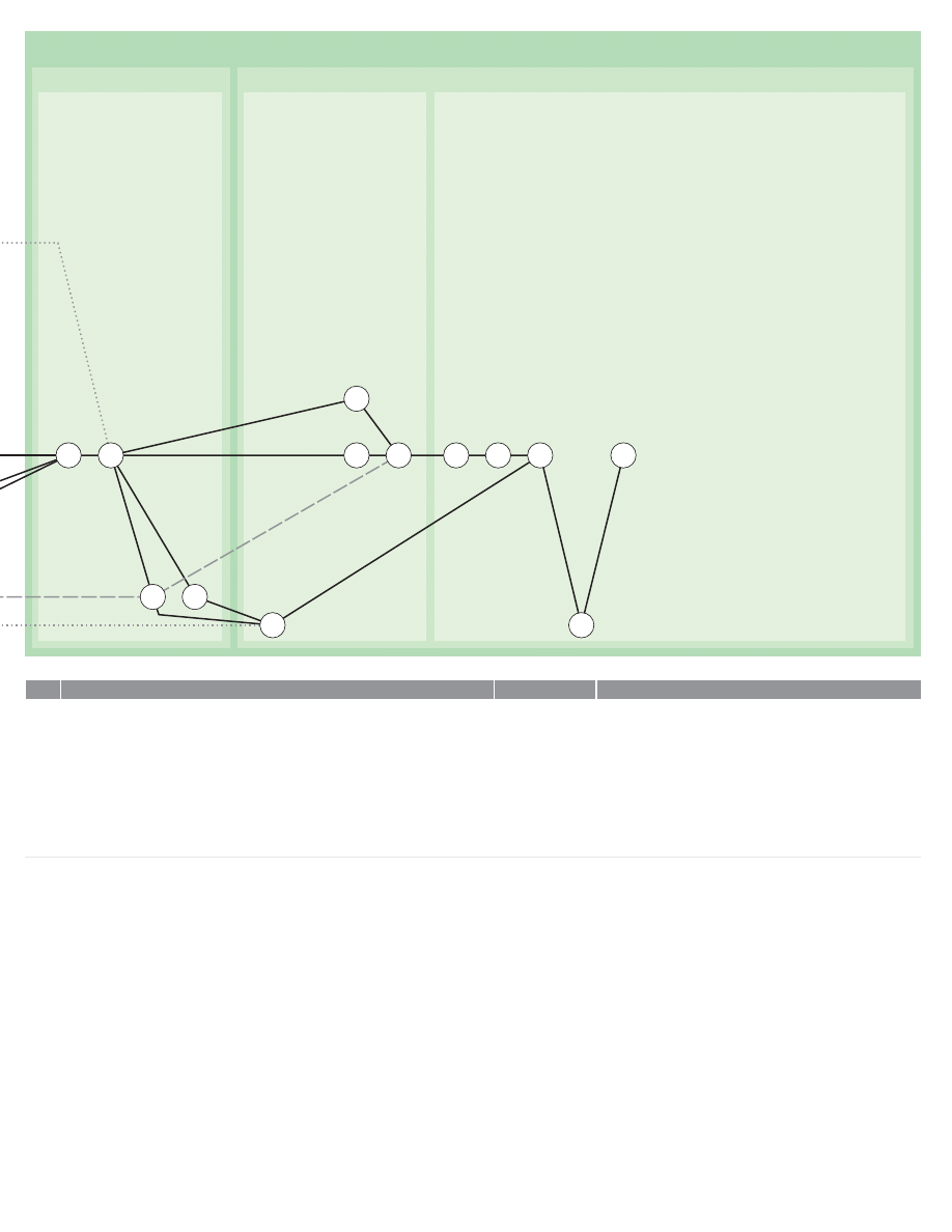
0HASE#ONTINUED
#OMMUNICATION#ONTINUED
0REPARE#OMMUNICATION#ONTINUED
7INDING5P
7IND5P0ROJECT
#LOSE2ECORDS
4RANSMIT)NFORMATION
-AKE3ECURITY!NDOR2ECORD#OPIES/F!LL$OCUMENTS
/R/THER-EDIA
#OMPILE4HE#OMMUNICATION3ET
#HECK&OR#OMPLETENESS
%NCLOSE!DDRESS!ND$ISPATCH4HE#OMMUNICATION
!DVISE$ISPATCH/F#OMMUNICATION4HROUGH!N!LTERNATIVE#HANNEL
)N4HE#ASE/F3KETCH$ESIGNS0REPARED5NDER#ONTINUE.OW&ROM
)N4HE#ASE/F&INAL$ESIGN3UBMISSIONS!WAIT!UTHORITY4O4ERMINATE0ROJECT/R
7HERE.ECESSARY2EITERATE&ROM
7INDING5P
7IND5P0ROJECT
,ABEL!ND3TORE#OPY/F4HE#OMMUNICATION!S$ISPATCHED
#OMPLETE#OPYRIGHT/R/THER!UXILIARY4RANSACTIONS
#OMPLETE&INANCIAL4RANSACTIONS!ND"OOK+EEPING
&ORMALLY$ISCHARGE/BLIGATIONS!ND#LOSE#ORRESPONDENCE
$ISENGAGE&ROM0ROBLEM!ND#LOSE0ROJECT
#LOSE2ECORDS
3TORE2ETURN$ISPOSE/F/R7RITE/FF!LL2EMAINING-ATERIALS!ND%QUIPMENT
$ESTROY!LL/BSOLETE!ND4RANSITORY-ATERIAL
#OLLATE,ABEL!ND3TORE!LL2ECORDS
!PPRAISE%XPERIENCE'AINED!ND!DJUST3YSTEMS!ND3TANDARDS
2ECORD#OPIES2EADY
#OMMUNICATION3ET#OMPILED
#OMMUNICATION3ET$ISPATCHED
!DVICE.OTE$ISPATCHED
#OMMUNICATION&ILED
!UXILIARY4RANSACTIONS#OMPLETE
&INANCIAL4RANSACTIONS!ND"OOK+EEPING#OMPLETE
#ORRESPONDENCE#LOSED
0ROJECT#LOSED
-ATERIALS!ND%QUIPMENT$ISPOSED/F
2EDUNDANT-ATERIAL$ISPOSED/F
2ECORDS3TORED
!PPRAISAL/F%XPERIENCE#OMPLETE
!CTIVITY
!CTIVITY.O
%VENT
)TEM
113
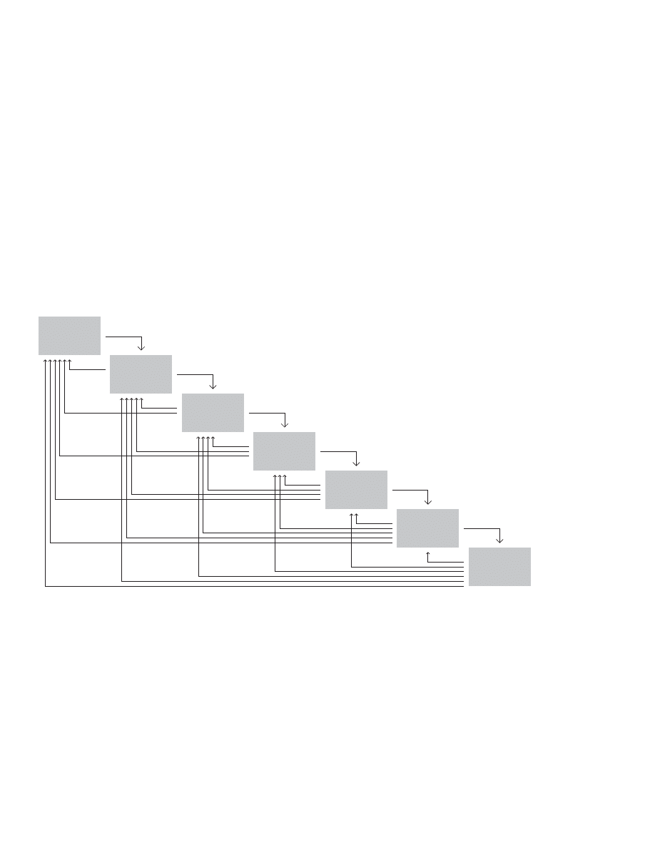
114
)DEATE
3ELECT
)MPLIMENTATION
%VALUATE
!CCEPT
3ITUATION
!NALYZE
$EFINE
Seven-step process as a cascade with feedback
after Don Koberg and Jim Bagnall (1972)
In this model, Koberg and Bagnall have added feedback
to their seven-stage model. (See page 16.) They note “one
stage need not follow another . . . It is also possible that the
stages can be considered in other ways . . . It could be cir-
cular . . . Others see it as a constant feedback system where
you never go forward without always looping back to check
on yourself; where one progresses by constant backward
relationships; and where the stages of the process advance
somewhat concurrently until some strong determining vari-
able terminates the process (time, money, energy, etc.)”
Koberg and Bagnall go on to describe alternatives: viewing
the design process as a branching system, and then as a
“horse race” where each stage proceeds concurrently rather
than a “mule train” where each stage proceeds one after the
next. Finally, they note, “Process never ends . . . its ultimate
model is the spiral, a continuum of sequential round trips
that go on ad infi nitum.”

Cyclic models
We tend to think of a process
in terms of steps—as a sequence.
But designers require feedback,
and most design processes
include feedback loops.
In this section we examine models
emphasizing feedback
and continuous improvement.
115

116
Process with feedback (archetype)
This simple model recalls our fi rst process model. (See page
12.) What’s added is a feedback loop. More precisely, some
of the output signal is split off and “fed back” into the input
signal.
This happens all the time in design—at many levels. (See
the previous spread.) We should be careful not to mistake
this schematic diagram (or circuit diagram) for the actual
design process. I include it here to underscore the impor-
tance of feedback in designing.
)NPUT
0ROCESS
&EEDBACK
/UTPUT

117
Goal-action-feedback loops
after Pangaro (2002)
Paul Pangaro describes feedback loops in terms of a goal-
action-effect-measurement cycle. In this model, a system
acts to accomplish a goal within its environment. The system
measures the effect its actions have on the environment and
compares the effect to its goal. Then the system looks for
errors and acts (or re-acts) to correct them. By repeating the
cycle, the system converges on a goal or maintains a steady
state. Feedback is the information loop fl owing from the sys-
tem through the environment and back into the system. (For
example, a boat pilot tacking to reach port or a thermostat
turning a heater on and then off.)
Designers follow this cycle. They have goals, act to accom-
plish them, and measure their results to see if they meet their
goals—goal-action-feedback. We’ve seen several analogs of
this process—defi ne-prototype-evaluate and design-build-
test. (See pages 50-51.)
Feedback is a central subject of cybernetics, the science of
goal-directed systems. Cybernetics has much to teach us
about fundamental structures of design.
'OAL
$ESIRED3TATE
%FFECT
#URRENT3TATE
!CTION
3YSTEMATTEMPTSTOREACHAGOAL
BASEDONFEEDBACK
ITMODIFIESITSACTIONS
3YSTEMACTSBOTHWITHINITSELF
ANDONITSENVIRONMENT
-EASUREMENT
3YSTEMMEASURESITSPROGRESS
COMPARINGCURRENTSTATETODESIREDSTATE
DETERMININGTHEDIFFERENCE
ANDATTEMPTINGTOCORRECTTHE@ERROR
&EEDBACK
TRANSFEROFINFORMATION
THROUGHENVIRONMENT
THROUGHSYSTEM

118
Second-order feedback loops
after Pangaro (2002)
measures the room temperature and decides whether to
raise or lower the set-point on the thermostat.)
As we’ve seen, designing involves not only achieving goals
but also defi ning them. Thus we may improve our model of
designing by nesting our original feedback loop within a sec-
ond feedback loop. See the next page for an example.
The model on the previous page assumes a constant goal.
That is, it provides no mechanism for changing or refi ning
the system’s goal. Typically, such systems are mechanical
(or electronic) and require humans to set their goals. (For
example, defi ning the set-point for a thermostat.) The human
creates a second loop in which the “action” is setting the
goal of the fi rst loop. (Like the thermostat, the human also
'OAL
$ESIRED3TATE
!CTION
3ECONDORDERSYSTEMATTEMPTSTOREACHITSGOAL
BYCONTROLLINGTHEGOALOFAFIRSTORDERSYSTEM
&EEDBACK,OOP
TRANSFEROFINFORMATION
THROUGHENVIRONMENT
THROUGHBOTHSYSTEMS
-EASUREMENT
3ECONDORDERSYSTEMMEASURESTHE
EFFECTOFTHEFIRSTORDERSYSTEMSACTION
"ASEDONTHATINFORMATIONTHESECOND
ORDERSYSTEMMODIFIESITSACTIONn
RESETTINGTHEGOALOFTHEFIRSTORDERSYSTEM
'OAL
$ESIRED3TATE
%FFECT
#URRENT3TATE
!CTION
&IRSTORDERSYSTEMATTEMPTSTOREACHAGOAL
BASEDONFEEDBACKITMODIFIESITSACTIONS
4HEFIRSTORDERSYSTEMACTSBOTHWITHINITSELF
ANDONITSENVIRONMENT
-EASUREMENT
3YSTEMMEASURESITSPROGRESS
COMPARINGCURRENTSTATETODESIREDSTATE
DETERMININGTHEDIFFERENCE
ANDATTEMPTINGTOCORRECTTHE@ERROR
&EEDBACK,OOP
TRANSFEROFINFORMATION
THROUGHENVIRONMENT
THROUGHTHEFIRSTORDERSYSTEM
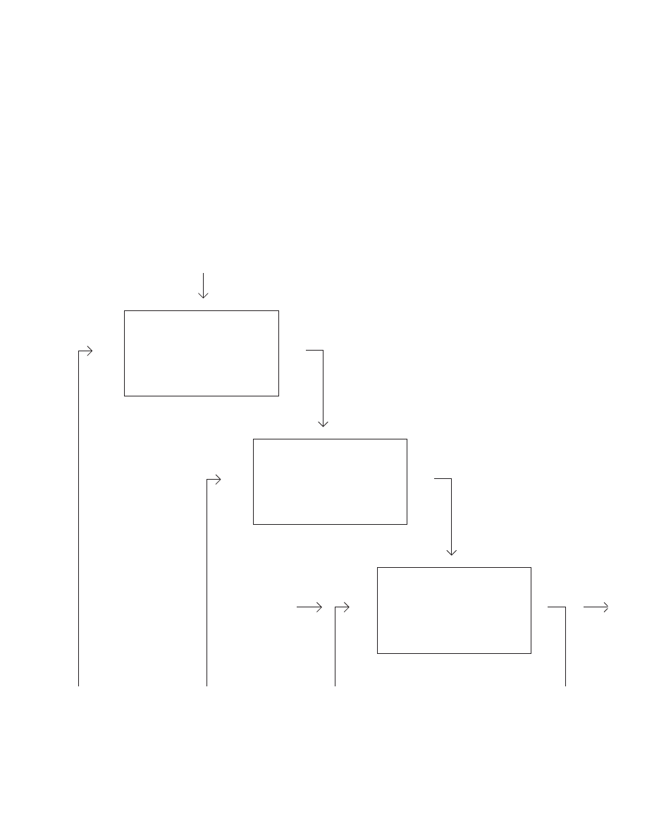
119
Bootstrapping or improving improvement
after Douglas Engelbart (1992)
PRODUCTION
LOCALPROCESS
GOALMAINTAINQUALITYOUTPUT
OUTPUT
INPUT
PROTOTYPE
LOCALQUALITYMANAGEMENTPROCESS
GOALIMPROVELOCALPROCESS
TESTCHANGE
OBSERVEPROBLEM
CODIFY
CORPORATEQUALITYMANAGEMENTPROCESS
GOALIMPROVEMEANSOFIMPROVEMENT
ROLLOUT
OBSERVESUCCESS
In 1992, Douglas Engelbart offered “an optimized bootstrap-
ping approach for drastically improving on any organization’s
already existing improvement processes.”
According to his foundation, Bootstrap.org, the process
works as follows, “Referring to an organization’s principal
work as an A-activity and to ordinary efforts at process im-
provement as a B-activity, he denotes bootstrapping as a C-
activity, which is an improving of the improvement process.
His paper ‘Toward High-Performance Organizations: A Stra-
tegic Role for Groupware’ argues that highest payoff comes
from engaging in that C-activity.”
Levels A, B, and C are analogous to fi rst-, second-, and
third-order feedback loops.
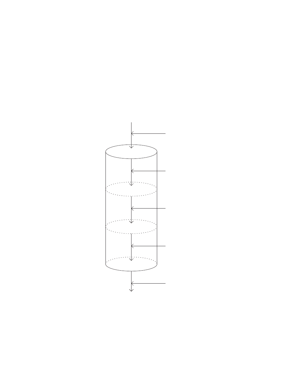
120
$ETAIL$ESIGN
#ONCEPT$ESIGN
3PECIFICATION
-ARKET
-ANUFACTURE
#ONCEPT3ELECTION
$ATA(ANDLING
)NFO!CQUISITION
3YNTHESIS
#OMPETITION
#OMPETITION!NALYSIS
/PTIMIZATION
#OST0ATTERNS
3ELL
-ARKET4RENDS
Product development process
after Stuart Pugh (1990)
Pugh published this model in his book, Total Design: Inte-
grated Methods for Successful Product Engineering. His
reasons for presenting it as a cylinder are not clear from
the diagram itself.
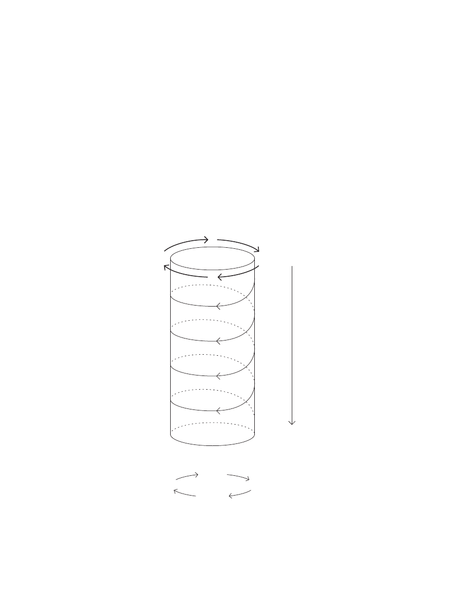
121
!
3
%
#
(OST%NVIRONMENT
#OMMUNICATION
%VALUATION
3YNTHESIS
!NALYSIS
#ONCRETE
!BSTRACT
0RODUCTION
0RODUCTION0LANNING
$ETAILED$ESIGN
0RELIMINARY$ESIGN
&EASIBILITY3TUDY
$EFINITIONOF.EED
Iconic model of the design process
after Mihajlo D. Mesarovic (1964)
In this model, Mesarovic employs a helix as the central struc-
ture, suggesting both a repeated cycle of steps and progress
through time.
Peter Rowe (1987) notes that Mesarovic’s model is similar
in structure to Asimow’s. (See pages 92-95.) “Throughout
this kind of account runs the assumption that it is possible
to discriminate distinct phases of activity and, further more,
that such distinctions have relevance to our understanding of
design.” Rowe continues, “The very maintenance of distinct
phases of activity, with a beginning and an end, and with
feedback loops among them, requires that objective per-
formance criteria can be explicitly stated in a manner that
fundamentally guides the procedure. Moreover, there is a
strong implication that the eventual synthesis of information
in the form of some designed object follows in a straightfor-
ward fashion from analysis of the problem at hand together
with likely performance criteria. Therefore, once a problem
has been defi ned, its solution is made directly accessible in
terms of that defi nition.” Rowe describes this view as “be-
haviorist” and also links it to “operations research”.
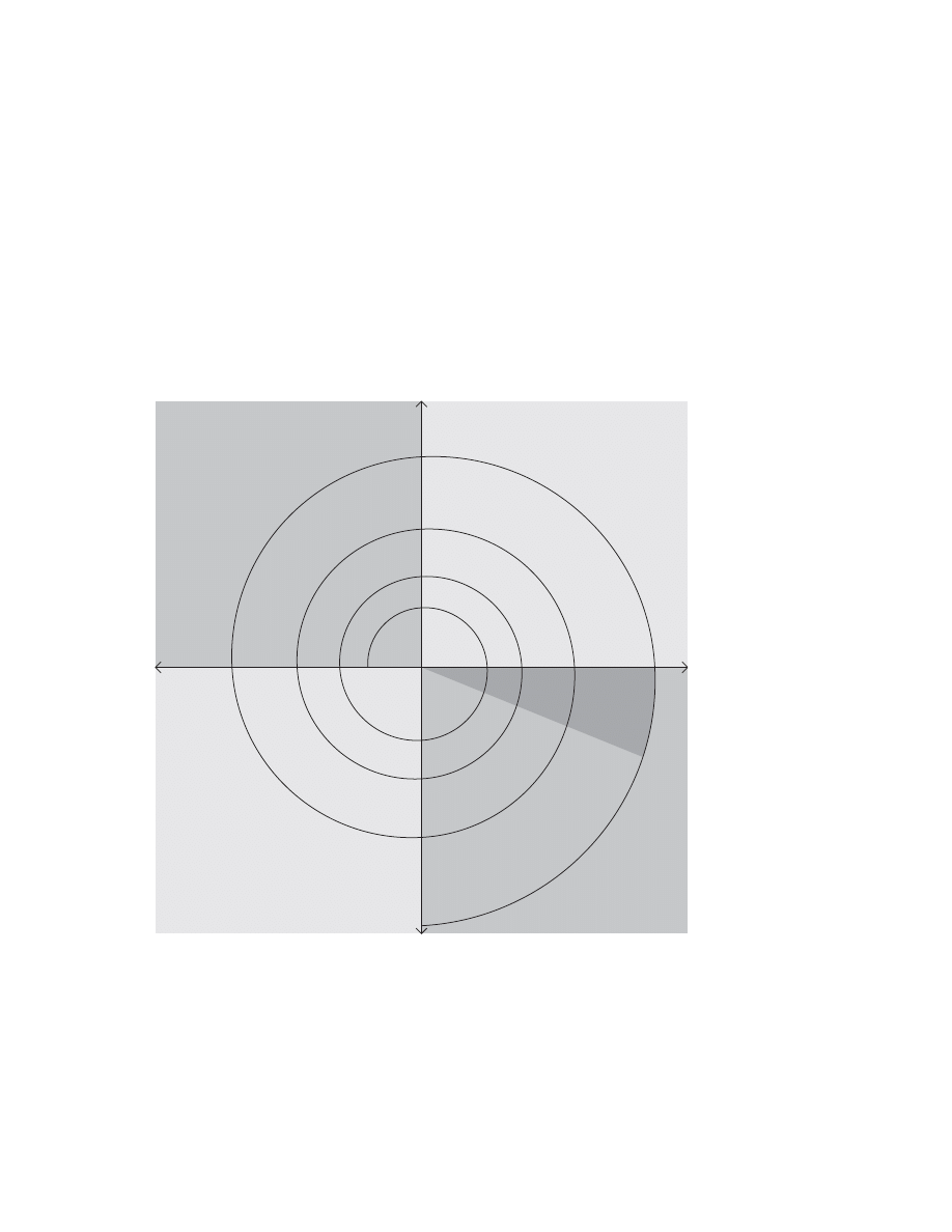
122
Boehm represented repeating cycles of design with a spiral
path moving away from a center starting point.
In addition to the spiral shape, Boehm introduces a focus on
risk reduction. Gary Schmidt of Washburn University offers
this description of Boehm’s model, “The radial dimension of
the model represents the cumulative costs when fi nishing the
steps. The angular dimension represents the progress made
in completing each cycle. Each loop of the spiral from x-axis
clockwise through 360 represents one phase. One phase is
split roughly into four sectors of major activities
- Objective setting
- Risk assessment and reduction
- Development and validation
- Planning the next phases”
$ETERMINE/BJECTIVES
!LTERNATIVESAND#ONSTRAINTS
0LAN.EXT0HASES
%VALUATE!LTERNATIVES
)DENTIFYAND2ESOLVE2ISKS
$EVELOPAND6ERIFY
0ROTOTYPE
0ROTOTYPE
/PERATIONAL
2ISK!NAYLSIS
2ISK!NAYLSIS
2ISK!NAYLSIS
2ISK!NAYLSIS
2EQUIREMENT0LAN
$EVELOPMENT0LAN
)NTEGRATIONAND4EST0LAN
#ONCEPT
2EQUIREMENTS6ALIDATION
$ESIGN6ALIDATIONAND6ERIFICATION
&INAL#ODE)MPLEMENTATIONAND4EST
3IMULATIONS-ODELSAND"ENCHMARKS
Spiral model of software development
after Barry Boehm (1986)
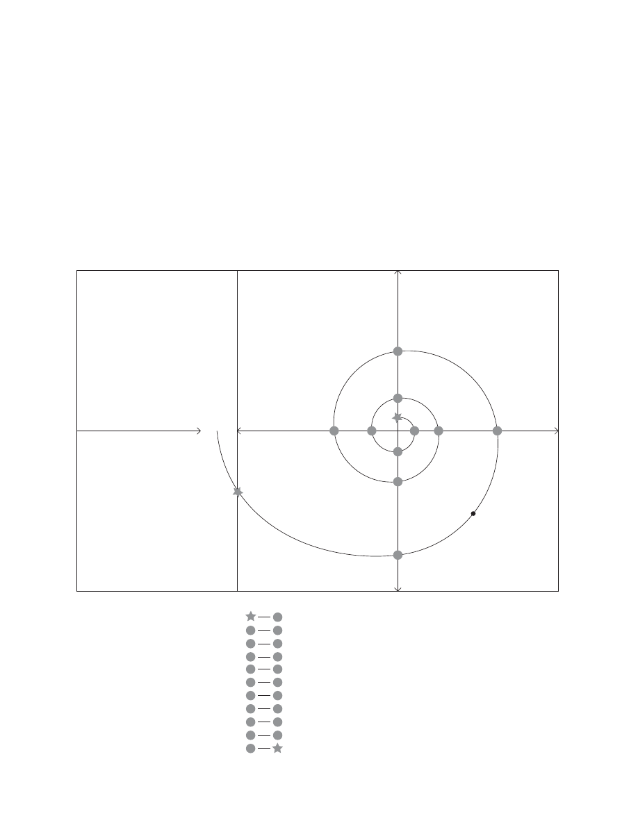
123
$ETERMINE
$ELVE
$EFINE
$ESIGN
$ESIGNAND
CONTENTFREEZE
!
"
#
$
%
&
'
(
)
*
#ODEFREEZE
,AUNCH
-OREGENERAL
LESSSPECIFICISSUES
NODETAILS
ARCHITECTURE
SKETCHES
ROUGHDRAFTOFCONTENT
QUICKPROTOTYPES
,ESSGENERAL
MORESPECIFICISSUES
5)DETAILS
CODEDEBUGGING
CONTENTTWEAKS
4HE"ODY-EDIA0RODUCT$EVELOPMENT0ROCESS-ODEL
ISBASEDON$R"ARRY"OEHMS3PIRALMETHODANDIS
DESIGNEDTOPROMOTE
FLEXIBILITY
PARALLELWORK
CONSTANTANDCLEARCOMMUNICATION
EFFICIENCY
SERENDIPITYANDSYNERGY
MULTIPLEITERATIONS
RAPIDPROTOTYPING
SMARTHUMANCENTRICSOLUTIONS
RISKMANAGEMENT
PREDICTABILITY
$EFINE
$ESIGN
$ELVE
$ETERMINE
$EFINE
$ESIGN
$ELVE
$ETERMINE
$EFINE
$ESIGN
&INALTESTINGAND1!,AUNCH
"RAINSTORMAND+ICKOFF
THE)NFORMATION!RCHITECTUREANDQUICKINTERACTIVEPROTOTYPES
INTOPROTOTYPEANDTESTTHEUSEFULLNESSOFTHEIDEA
THEWEAKNESSSTRENGTHSANDRISKSTIMECONSTRAINTS
NEWALTERNATIVESANDSOLUTIONS
UPDATEARCHITECTURECONTENTCODEAND5)OFINTERACTIVEPORTOTYPE
INTOREFINEDSOLUTIONTESTFORUSABILITYANDMAJORBUGS
SOLUTIONSWEAKNESSESSTRENGHTSRISKSTIMECONSTRAINTS
WHATNEEDSTOCANCHANGEWITHCODE5)
$ESIGNANDCONTENTFREEZESALLSPECSDUE#ODEFREEZE
!
*
"
!
#
"
$
#
%
$
&
%
'
&
(
'
)
(
*
)
BodyMedia product development process
after Chris Pacione (2002)
In his book, What Is Web Design?, Nico MacDonald (2003)
published a similar model Pacione developed for his compa-
ny, BodyMedia. MacDonald notes, “The model requires that
the product must be the right thing to make, posits designers
as synthesizers and indicates the relationship with users is
on-going.” Note also Pacione’s variation on the 4Ds—in this
case defi ne-design-delve-determine. (See page 62.)
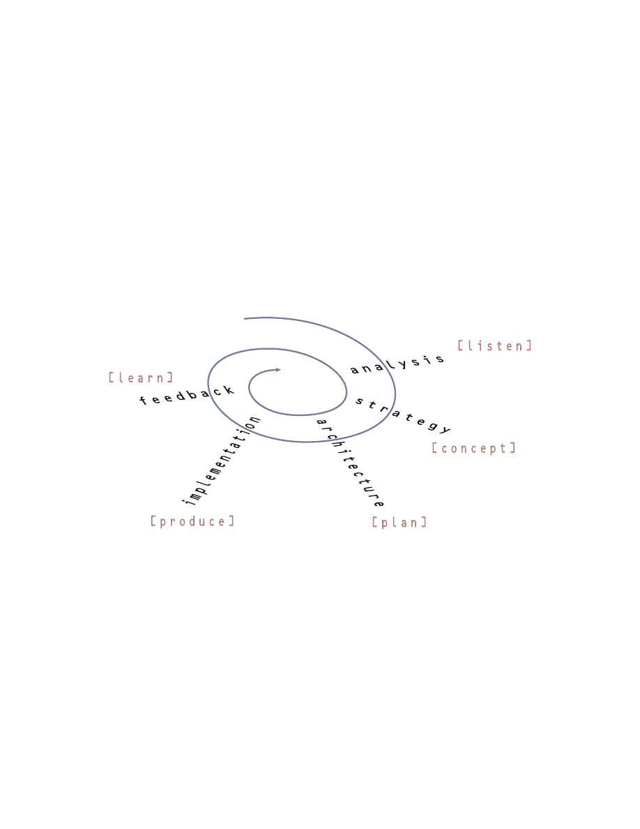
124
Souza also used a spiral path to represent repeating cycles
in the design process. In Boehm’s model, the spiral travels
out from the center suggesting—though perhaps not inten-
tionally—that the process diverges. Traveling outward could
also suggest adding increasing amounts of detail. In Souza’s
model, the path travels in toward the center suggesting the
process converges on a goal.
Design process
after Paul Souza (1996)

125
2EAL
!BSTRACT
!NALYSIS
2ESEARCH
3YNTHESIS
$ELIVERY
&RAME
)NSIGHTS
h!HAv
%XPLORE
#ONCEPTS
h%UREKAv
-AKE
0LANS
-AKE
+NOW
)MPLEMENT
[
0ROTOTYPE
0ILOT
,AUNCH
2EALIZE
/FFERINGS
+NOW
5SER
+NOW
#ONTEXT
(YPOTHESIS
Innovation planning
after Vijay Kumar (2003)
Kumar presented this model at the 2003 HITS Conference
(Humans, Interaction, Technology, Strategy) in Chicago. He
described modes of planning (rather than steps) emphasizing
the iterative and interconnected nature of the design pro-
cess. He has also mapped tools and methods onto each of
the modes. He spoke of innovation as the jump from insight
to concept—from aha to eureka—describing it as a revela-
tion, magic, genius, intuition, a hunch.
Kumar teaches at the Illinois Institute of Technology’s Insti-
tute of Design; his teaching and research includes a focus
on understanding innovation.
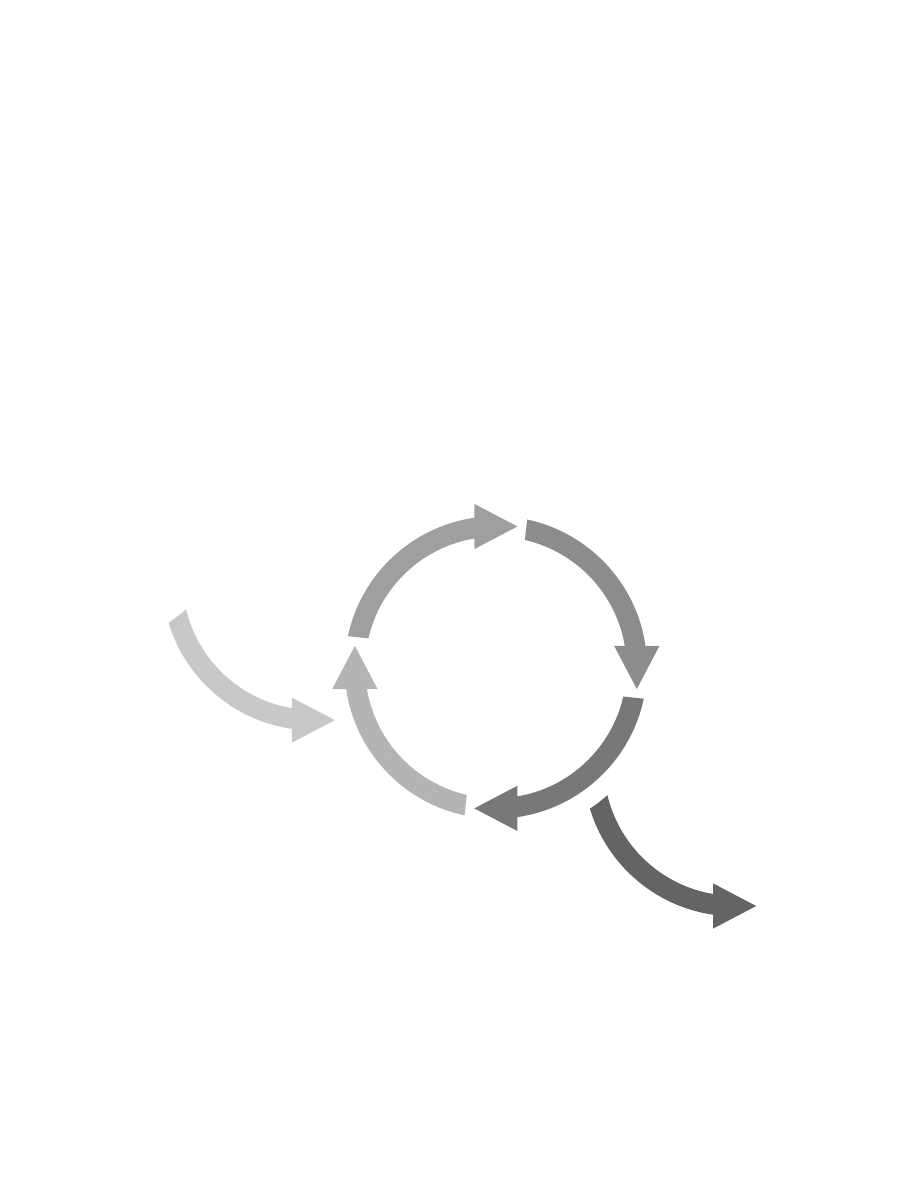
126
"USINESS-ODELING
)NITIAL0LANNING
!NALYSISAND$ESIGN
4EST
0LANNING
2EQUIREMENTS
)MPLEMENTATION
%VALUATION
$EPLOYMENT
#ONFIGURATIONAND#HANGE
-ANAGEMENT
%NVIRONMENT
Rational Unifi ed Process iteration cycle
after Per Kroll (2004)
Iteration is a central principle of the Rational unifi ed process.
Kroll notes, “Each iteration includes some or most of the
development disciplines (requirements, analysis, design,
implementation and [testing activities]. Each iteration also
has a well-defi ned set of objectives and produces a partial
working implementation of the fi nal system. And each suc-
cessive iteration builds on the work of previous iterations
to evolve and refi ne the system until the fi nal product is
complete. Early iterations emphasize requirements as well as
analysis and design; later iterations emphasize implementa-
tion and testing.”
Knoll suggests four principles:
1. Build functional prototypes early.
2. Divide the detailed design, implementation and test
phases into iterations.
3. Baseline an executable architecture early on.
4. Adopt an iterative and risk-driven management process.
Kroll is director of the Rational Unifi ed Process development
and product management teams at IBM. (For another model
of RUP, see page 67.)

127
2ELEASE0LAN
#ODE
)TERATION0LAN
!CCEPTANCE4EST
3TAND5P-EETING
5NIT4EST
0AIR.EGOTIATION
0AIR0ROGRAMMING
-ONTHS
7EEKS
$AYS
(OURS
/NE$AY
-INUTES
3ECONDS
Extreme programming planning/feedback loops
after Don Wells (2000)
Extremeprogramming.org published this hypertext model
depicting nested feedback loops within the XP development
process. The length of each loop increases from bottom to
top of the model. The model also serves as a sort of table of
contents for key ideas in extreme programming. (For other
models of extreme programming, see pages 70-71.)

128
4HE$ESIGN0ROCESS
-AINTAINABILITY
2ELIABILITY
3YNTHESIS
!NALYSIS
4ESTING
-ATERIAL
3ELECTION
!VAILABILITY
#OST"ENEFIT
-ANUFACTURABILITY
$EPENDABILITY
Engineering design process
after Atila Ertas and Jesse C. Jones (1996)
This model is interesting in its use of the gear metaphor.
Did the authors intend to frame design as a mechanical pro-
cess? It’s also unusual to see a model begin with synthesis—
or include “materials selection” at the same level of abstrac-
tion. The inclusion of the six considerations or constraints is
also unusual.

129
0LANNING
2EQUIREMENTS
$ESIGN
$EVELOPMENT
3YSTEM4EST
0RODUCT2ELEASE
/UR&OCUS
n5SERANALYSISREQUIREMENTS
n0RODUCTDEFINITIONDESIGN
ANDDEVELOPMENTFOREASEOFUSE
ANDUSEFULNESS
/THER%LEMENTSOFTHE#USTOMER%XPERIENCE
n/RDERINGDELIVERY
n$OCUMENTATION
n)NSTALLATION
n)NTEGRATIONWITHRDPARTYPRODUCTS
n#USTOMERSUPPORT
Product development process: overview
after Hewlett Packard (circa 2000)
Loops or circular layouts are curiously rare in design process
models—with the notable exception of the PDCA cycle on
the next page. Koberg and Bagnall provide another example
by simply turning their seven-step process into a circle.
130
0LAN
$O
!CT
#HECK
#ARRYOUTTHECHANGEORTHETEST
PREFERABLYINAPILOTORONASMALLSCALE
#HECKIFTHEDESIREDRESULTWASACHIEVED
WHATIFANYTHINGWENTWRONG
ANDWHATWASLEARNED
$ETERMINETHEROOTCAUSEOFTHEPROBLEM
THENPLANACHANGEORATEST
AIMEDATIMPROVEMENT
!DOPTTHECHANGE
IFTHEDESIREDRESULTWASACHIEVED
)FTHERESULTWASNOTDESIRED
REPEATTHECYCLEUSINGKNOWLEDGEOBTAINED
PDCA quality cycle
after Walter A. Shewart (1939)
Edward Deming worked with Shewhart at Bell Laboratories
and later popularized the PDCA cycle, especially in Japan.
Deming substituted “study” for “check”. PDCA and PDSA
have many incarnations and many defi nitions. For example,
the ISO 9001 standard includes the PDCA cycle. Over the
last 20 years, the focus of quality management has expand-
ed from manufacturing processes to include a systemic view
of customer satisfaction.
PDCA stands for plan-do-check-act cycle of continuous
improvement, a standard principle of quality assurance and
management. It is also known as the Shewhart cycle or the
Deming cycle.
The mathematician Walter A. Shewhart was concerned
with what he called “the formulation of a scientifi c basis for
securing economic control.” In 1939, he published Statistical
Method from the Viewpoint of Quality Control, the fi rst place
he discussed the PDCA concept, according to the American
Society for Quality (ASQ).
131
)NTERPRET
$ECIDE
3ENSE
!CT
5SEAVARIETYOFTECHNOLOGIESANDTECHNIQUETO
UNDERSTANDTHEMEANINGOFWHATYOURPROBESARE
SENSINGANDWHYCOMMITMENTSBETWEENROLES
BREAKDOWN&OREXAMPLESCENARIOPLANNINGCAN
HELPIDENTIFYANDPREPAREFORWAYSTHEFUTUREMAY
UNFOLDWARGAMINGHELPSLEADERSTHINKTHROUGH
VARIOUSRESPONSESTOCHANGEANDCOLLABORATIVE
DECISIONMAKINGHELPSLEADERSDECIDEHOWTO
ALLOCATELIMITEDRESOURCESINUNPREDICTABLE
ENVIRONMENTS4HISINFORMATIONSHOULDBE
VIEWABLEONSCREEN
3HOULDORGANIZATIONSRAISONDÐTREPOLICIES
ORROLEANDACCOUNTABILITYDESIGNCHANGE&OR
EXAMPLEIFCOMMITMENTSAREREPEATEDLYBROKEN
IFNEWCAPABILITIESARENTBEINGINCORPORATEDETC
&REQUENTLYCHALLENGEDPOLICIESMIGHTNEEDTOBE
RELAXEDTIGHTENEDORELIMINATED4HERAISONDÐTRE
MIGHTNEEDCHANGINGIFTHEREAREBIGORSUDDEN
SHIFTSINTHEMARKETPLACEORINTHEVALUESAND
PREFERENCESOFYOURMOSTIMPORTANTCUSTOMERS
ANDOTHERCONSTITUENTS
$EPLOYSPROBESANDGATHERAWIDERANGEOF
SIGNALSFROMHARDDATATOFINANCAILREPORTSTO
CONVERSATIONSWITHCUSTOMERSTOSPOTIMPENDING
CHANGEINYOURBUSINESSENVIRONMENTYOUR
CUSTOMERSBUSINESSESANDTHEIRCUSTOMERS
BUSINESSES)NTERNALLYTRACKBREAKDOWNSINYOUR
ORGANIZATIONSPERFORMANCEANDVIOLATIONSOF
COMMITMENTSANDBASICRULES3CANFOR
CAPABILITIESFIRMSINOTHERINDUSTRIESHAVETHATYOU
MIGHTFINDUSEFUL!LLDATASHOULDBEVIEWABLEON
0#SANDHANDHELDS
!SLEADERPUBLICLYPROCLAIMTHENEWRAISONDÐTRE
BASICRULESANDROLESORIFNOCHANGEISREQUIRED
ATTHETIMEAFFIRMTHEOLDONES7HENCHANGING
ANYROLESMAKESURETHERIGHTPEOPLEEXECUTE
THEMANDTHATTHEIRCOMMITMENTSTOOTHERSWITHIN
THEORGANIZATIONAREADJUSTEDTOREFLECTANYNEW
DESIREDOUTCOMES,IKEWISEINSTALLORUPGRADE
ELECTRONICINFORMATIONSYSTEMSTODISPLAYTHE
UPDATEDCOMMITMENTSASWELLASANYNEW
hSENSEvANDhINTERPRETvINFORMATIONNOWREQUIRED
Adaptability loop
after Stephan H. Haeckel (2003)
Haeckel proposed this process for managing within a chang-
ing environment. At fi rst, it appears to be a classic feed-
back-based control loop. But the options for action include
changing goals and thus suggest a more complex process
than is represented in the model.
Haeckel’s model may also be interpreted as a variation
on the classic PDCA cycle. It’s interesting to note that the
PDCA cycle also implies but does not represent a process
for changing goals. (Some variations on the model include
it.) The authors may have chosen a simpler representation
to make it easy to communicate and remember.

132
Complete list of models
Introducing process
10
Design Process
after Tim Brennan (~1990)
12
Process archetype
13
On the infi nite expandability of process models
14
Design process archetype: Analysis, Synthesis
after Koberg and Bagnall (1972)
15
Problem, Solution
after JJ Foreman (1967)
16
Expanding the two-step process
after Don Koberg and Jim Bagnall (1972)
17
Matching process to project complexity
after Jay Doblin (1987)
18
Unself-conscious and self-conscious design
after Christopher Alexander (1962)
Analysis synthesis evaluation
20
Oscillation
21
Programming and designing
after William M. Pena and Steven A. Parshall (1969)
22
Diverge / Converge vs Narrow / Expand
23
Decomposition / recombination
after VDI 2221 (from Cross 1990)
24
Dynamics of divergence and convergence
after Bela H. Banathy (1996)
25
Overall, the design process must converge
after Nigel Cross (2000)
26
Gradual shift of focus from analysis to synthesis
after Bill Newkirk (1981)
27
Problem to solution: sequence or parallel process or loop?
Academic models
28
Walking process
after Lawson (1980)
30
Four-stage design process
after Nigel Cross (2000)
31
Engineering design process
after Michael J. French (1985)
32
VDI 2221: System Approach to the Design of Technical
Systems and Products
after Verein Deutscher Ingenieure (1987)
33
Design process
after Gerhard Pahl and Wolfgang Beitz (1984)
34
Architect’s Plan of Work (schematic)
after the Royal Institute of British Architects Handbook (1965)
35
Architect’s Plan of Work, (detailed)
after the RIBA Handbook (1965)
36
Problem solving process
after George Polya (1945)
37
Scientifi c problem solving process
after Cal Briggs and Spencer W. Havlick (1976)
38
THEOC, a model of the scientifi c method

133
39
Criteria of validation of scientifi c explanations (CVSE)
after Humberto Maturana (1987)
40
Comprehensive anticipatory design science
after Buckminster Fuller (1978?)
41
Design Process and Practice
after Richard Buchannan (1997)
42
Creative process
after Bryan Lawson (1980)
43
Primary generator
after Jane Darke (1978)
44
Design process
after Jane Darke (1978)
45
Design process
after Thomas A. Marcus (1969) and Thomas W Maver (1970)
47
Process of designing solutions
after Clement Mok and Keith Yamashita (2003)
48
Case study, using the AIGA process in Iraq
by Nathan Felde (2003)
49
What the AIGA didn’t tell you
by Nathan Felde (2003)
51
Design, build, test (1 of 3)
after Alice Agogino
52
Design, build, test (2 of 3)
after Alice Agogino
53
Design, build, test (3 of 3)
after Alice Agogino
54
Mechanical engineering design process
after students at UC Berkeley Institute of Design (BID)
55
New product development process
after Steven D. Eppinger and Karl T. Ulrich (1995)
57
Design Process
after John Chris Jones (1970)
58
Value analysis
after John Chris Jones (1970)
59
Man-machine system designing
after John Chris Jones (1970)
Consultant models
60
Eight phases of a project
Sometimes presented as six phases of a project
62
4D software process
and variations
63
IT consulting process overview
after Mindtree Consulting
65
IDEO
(2004)
66
Trees
Software development models
68
Waterfall lifecycle
after Philippe Kruchten (2004)
69
Rational Unifi ed Process (RUP)
after Phillippe Kruchten (2003)

134
70
Extreme Programming (XP) Process
after Don Wells (2000)
72
V model
Paul Rock (~1980), IABG (1992)
73
Joint Application Development (JAD)
after Jane Wood and Denise Silver (1995)
74
PMBOK (Project Management Body of Knowledge)
PMI (Project Management Institute) (1987)
75
ISO 13407 Human-centered design processes for interactive
systems
Tom Stewart et al. (1999)
76
User-centered design process (UCD)
after Karel Vredenburg (2003)
77
Relation of UCD to IPD and Business Management
after Karel Vredenburg (2003)
78
Sun Sigma Framework
DMADV methodology for new products
79
Sun Sigma Framework
DMAIC methodology for improving existing products
80
Sun Product Lifecycle (PLC)
Sun Software Development Framework (SDF)
“Mapped” processes for product instances
81
Sun Product Lifecycle (PLC)
Sun Software Development Framework (SDF)
“Mapped” processes for product lines
Complex linear models
84
Web development process
after Vanguard Group (circa 1999)
87
Evolution of the software development process
after Alan Cooper (2001)
88
Goal-directed design process
after Alan Cooper (2001)
90
Idealized process of developing buildings
after Alan Cooper (2004)
91
Idealized process of developing software
after Alan Cooper (2004)
93
Morphology of design
after Morris Asimow (1962)
97
Biological sequence of problem solving
after Bruce Archer (1963-1964)
98
Basic design procedure
after Bruce Archer (1963-1964)
99
Check list for product designers
Bruce Archer (1963-1964)
Cyclic models
114
Seven-step process as a cascade with feedback
after Don Koberg and Jim Bagnall (1972)
116
Process with feedback (archetype)
117
Goal-action-feedback loops
after Pangaro (2002)
118
Second-order feedback loops
after Pangaro (2002)
119
Bootstrapping or improving improvement
after Douglas Engelbart (1992)
Complete list of models
continued

135
120
Product development process
after Stuart Pugh (1990)
121
Iconic model of the design process
after Mihajlo D. Mesarovic (1964)
122
Spiral model of software development
after Barry Boehm (1986)
123
BodyMedia product development process
after Chris Pacione (2002)
124
Design process
Paul Souza (1999?)
125
Innovation planning
after Vijay Kumar (2003)
126
Rational Unifi ed Process iteration cycle
Per Kroll (2004)
127
Extreme programming planning/feedback loops
after Don Wells (2000)
128
Engineering design process
after Atila Ertas and Jesse C. Jones (1996)
129
Product development process: overview
Hewlett Packard (circa 2000)
130
PDCA quality cycle
after Walter A. Shewart (1939)
131
Adaptability loop
after Stephan H. Haeckel (2003)

136
Chronological list
130
PDCA quality cycle
after Walter A. Shewart (1939)
36
Problem solving process
after George Polya (1945)
18
Unself-conscious and self-conscious design
after Christopher Alexander (1962)
93
Morphology of design
after Morris Asimow (1962)
97
Biological sequence of problem solving
after Bruce Archer (1963-1964)
98
Basic design procedure
after Bruce Archer (1963-1964)
99
Check list for product designers
Bruce Archer (1963-1964)
121
Iconic model of the design process
after Mihajlo D. Mesarovic (1964)
34
Architect’s Plan of Work (schematic)
after the Royal Institute of British Architects Handbook (1965)
35
Architect’s Plan of Work, (detailed)
after the RIBA Handbook (1965)
15
Problem, Solution
after JJ Foreman (1967)
45
Design process
after Thomas A. Marcus (1969) and Thomas W Maver (1970)
21
Programming and designing
after William M. Pena and Steven A. Parshall (1969)
57
Design Process
after John Chris Jones (1970)
58
Value analysis
after John Chris Jones (1970)
59
Man-machine system designing
after John Chris Jones (1970)
14
Design process archetype: Analysis, Synthesis
after Koberg and Bagnall (1972)
16
Expanding the two-step process
after Don Koberg and Jim Bagnall (1972)
114
Seven-step process as a cascade with feedback
after Don Koberg and Jim Bagnall (1972)
37
Scientifi c problem solving process
after Cal Briggs and Spencer W. Havlick (1976)
43
Primary generator
after Jane Darke (1978)
44
Design process
after Jane Darke (1978)
40
Comprehensive anticipatory design science
after Buckminster Fuller (1978?)
28
Walking process
after Lawson (1980)
42
Creative process
after Bryan Lawson (1980)
26
Gradual shift of focus from analysis to synthesis
after Bill Newkirk (1981)

137
33
Design process
after Gerhard Pahl and Wolfgang Beitz (1984)
31
Engineering design process
after Michael J. French (1985)
122
Spiral model of software development
after Barry Boehm (1986)
17
Matching process to project complexity
after Jay Doblin (1987)
39
Criteria of validation of scientifi c explanations (CVSE)
after Humberto Maturana (1987)
74
PMBOK (Project Management Body of Knowledge)
PMI (Project Management Institute) (1987)
32
VDI 2221: System Approach to the Design of Technical
Systems and Products
after Verein Deutscher Ingenieure (1987)
10
Design Process
after Tim Brennan (~1990)
23
Decomposition / recombination
after VDI 2221 (from Cross 1990)
120
Product development process
after Stuart Pugh (1990)
119
Bootstrapping or improving improvement
after Douglas Engelbart (1992)
72
V model
Paul Rock (~1980), IABG (1992)
55
New product development process
after Steven D. Eppinger and Karl T. Ulrich (1995)
73
Joint Application Development (JAD)
after Jane Wood and Denise Silver (1995)
24
Dynamics of divergence and convergence
after Bela H. Banathy (1996)
128
Engineering design process
after Atila Ertas and Jesse C. Jones (1996)
41
Design Process and Practice
after Richard Buchannan (1997)
124
Design process
Paul Souza (1999?)
75
ISO 13407 Human-centered design processes for interactive
systems
Tom Stewart et al. (1999)
84
Web development process
after Vanguard Group (circa 1999)
129
Product development process: overview
Hewlett Packard (circa 2000)
25
Overall, the design process must converge
after Nigel Cross (2000)
30
Four-stage design process
after Nigel Cross (2000)
70
Extreme Programming (XP) Process
after Don Wells (2000)
127
Extreme programming planning/feedback loops
after Don Wells (2000)
87
Evolution of the software development process
after Alan Cooper (2001)

138
Chronological list
continued
88
Goal-directed design process
after Alan Cooper (2001)
123
BodyMedia product development process
after Chris Pacione (2002)
117
Goal-action-feedback loops
after Pangaro (2002)
118
Second-order feedback loops
after Pangaro (2002)
47
Process of designing solutions
after Clement Mok and Keith Yamashita (2003)
48
Case study, using the AIGA process in Iraq
by Nathan Felde (2003)
49
What the AIGA didn’t tell you
by Nathan Felde (2003)
131
Adaptability loop
after Stephan H. Haeckel (2003)
69
Rational Unifi ed Process (RUP)
after Phillippe Kruchten (2003)
125
Innovation planning
after Vijay Kumar (2003)
76
User-centered design process (UCD)
after Karel Vredenburg (2003)
77
Relation of UCD to IPD and Business Management
after Karel Vredenburg (2003)
90
Idealized process of developing buildings
after Alan Cooper (2004)
91
Idealized process of developing software
after Alan Cooper (2004)
65
IDEO
(2004)
126
Rational Unifi ed Process iteration cycle
Per Kroll (2004)
68
Waterfall lifecycle
after Philippe Kruchten (2004)

139
Dates not found
51
Design, build, test (1 of 3)
after Alice Agogino
52
Design, build, test (2 of 3)
after Alice Agogino
53
Design, build, test (3 of 3)
after Alice Agogino
54
Mechanical engineering design process
after students at UC Berkeley Institute of Design (BID)
60
Eight phases of a project
Sometimes presented as six phases of a project
62
4D software process
and variations
63
IT consulting process overview
after Mindtree Consulting
66
Trees
78
Sun Sigma Framework
DMADV methodology for new products
79
Sun Sigma Framework
DMAIC methodology for improving existing products
80
Sun Product Lifecycle (PLC)
Sun Software Development Framework (SDF)
“Mapped” processes for product instances
81
Sun Product Lifecycle (PLC)
Sun Software Development Framework (SDF)
“Mapped” processes for product lines
Produced for this book (2004)
116
Process with feedback (archetype)
12
Process archetype
13
On the infi nite expandability of process models
19
*Analysis synthesis evaluation
20
Oscillation
22
Diverge / Converge vs Narrow / Expand
27
Problem to solution: sequence or parallel process or loop?
38
THEOC, a model of the scientifi c method

140
Author list
51
Design, build, test (1 of 3)
after Alice Agogino
52
Design, build, test (2 of 3)
after Alice Agogino
53
Design, build, test (3 of 3)
after Alice Agogino
18
Unself-conscious and self-conscious design
after Christopher Alexander (1962)
97
Biological sequence of problem solving
after Bruce Archer (1963-1964)
98
Basic design procedure
after Bruce Archer (1963-1964)
99
Check list for product designers
Bruce Archer (1963-1964)
93
Morphology of design
after Morris Asimow (1962)
24
Dynamics of divergence and convergence
after Bela H. Banathy (1996)
122
Spiral model of software development
after Barry Boehm (1986)
10
Design Process
after Tim Brennan (~1990)
37
Scientifi c problem solving process
after Cal Briggs and Spencer W. Havlick (1976)
41
Design Process and Practice
after Richard Buchannan (1997)
87
Evolution of the software development process
after Alan Cooper (2001)
88
Goal-directed design process
after Alan Cooper (2001)
90
Idealized process of developing buildings
after Alan Cooper (2004)
91
Idealized process of developing software
after Alan Cooper (2004)
25
Overall, the design process must converge
after Nigel Cross (2000)
30
Four-stage design process
after Nigel Cross (2000)
43
Primary generator
after Jane Darke (1978)
44
Design process
after Jane Darke (1978)
17
Matching process to project complexity
after Jay Doblin (1987)
119
Bootstrapping or improving improvement
after Douglas Engelbart (1992)
55
New product development process
after Steven D. Eppinger and Karl T. Ulrich (1995)
128
Engineering design process
after Atila Ertas and Jesse C. Jones (1996)
48
Case study, using the AIGA process in Iraq
by Nathan Felde (2003)

141
49
What the AIGA didn’t tell you
by Nathan Felde (2003)
131
Adaptability loop
after Stephan H. Haeckel (2003)
15
Problem, Solution
after JJ Foreman (1967)
31
Engineering design process
after Michael J. French (1985)
40
Comprehensive anticipatory design science
after Buckminster Fuller (1978?)
129
Product development process: overview
Hewlett Packard (circa 2000)
65
IDEO
(2004)
57
Design Process
after John Chris Jones (1970)
58
Value analysis
after John Chris Jones (1970)
59
Man-machine system designing
after John Chris Jones (1970)
14
Design process archetype: Analysis, Synthesis
after Koberg and Bagnall (1972)
16
Expanding the two-step process
after Don Koberg and Jim Bagnall (1972)
114
Seven-step process as a cascade with feedback
after Don Koberg and Jim Bagnall (1972)
126
Rational Unifi ed Process iteration cycle
Per Kroll (2004)
69
Rational Unifi ed Process (RUP)
after Phillippe Kruchten (2003)
68
Waterfall lifecycle
after Philippe Kruchten (2004)
125
Innovation planning
after Vijay Kumar (2003)
28
Walking process
after Lawson (1980)
42
Creative process
after Bryan Lawson (1980)
45
Design process
after Thomas A. Marcus (1969) and Thomas W Maver (1970)
39
Criteria of validation of scientifi c explanations (CVSE)
after Humberto Maturana (1987)
121
Iconic model of the design process
after Mihajlo D. Mesarovic (1964)
63
IT consulting process overview
after Mindtree Consulting
47
Process of designing solutions
after Clement Mok and Keith Yamashita (2003)
26
Gradual shift of focus from analysis to synthesis
after Bill Newkirk (1981)
123
BodyMedia product development process
after Chris Pacione (2002)

142
Author list
continued
33
Design process
after Gerhard Pahl and Wolfgang Beitz (1984)
117
Goal-action-feedback loops
after Pangaro (2002)
118
Second-order feedback loops
after Pangaro (2002)
21
Programming and designing
after William M. Pena and Steven A. Parshall (1969)
74
PMBOK (Project Management Body of Knowledge)
PMI (Project Management Institute) (1987)
36
Problem solving process
after George Polya (1945)
120
Product development process
after Stuart Pugh (1990)
34
Architect’s Plan of Work (schematic)
after the Royal Institute of British Architects Handbook (1965)
35
Architect’s Plan of Work, (detailed)
after the RIBA Handbook (1965)
72
V model
Paul Rock (~1980), IABG (1992)
130
PDCA quality cycle
after Walter A. Shewart (1939)
124
Design process
Paul Souza (1999?)
75
ISO 13407 Human-centered design processes for interactive
systems
Tom Stewart et al. (1999)
78
Sun Sigma Framework
DMADV methodology for new products
79
Sun Sigma Framework
DMAIC methodology for improving existing products
80
Sun Product Lifecycle (PLC)
Sun Software Development Framework (SDF)
“Mapped” processes for product instances
81
Sun Product Lifecycle (PLC)
Sun Software Development Framework (SDF)
“Mapped” processes for product lines
84
Web development process
after Vanguard Group (circa 1999)
76
User-centered design process (UCD)
after Karel Vredenburg (2003)
77
Relation of UCD to IPD and Business Management
after Karel Vredenburg (2003)
32
VDI 2221: System Approach to the Design of Technical
Systems and Products
after Verein Deutscher Ingenieure (1987)
23
Decomposition / recombination
after VDI 2221 (from Cross 1990)
70
Extreme Programming (XP) Process
after Don Wells (2000)
127
Extreme programming planning/feedback loops
after Don Wells (2000)
73
Joint Application Development (JAD)
after Jane Wood and Denise Silver (1995)

143
Authors not identifi ed
54
Mechanical engineering design process
after students at UC Berkeley Institute of Design (BID)
60
Eight phases of a project
Sometimes presented as six phases of a project
62
4D software process
and variations
66
Trees
Produced for this book (2004)
116
Process with feedback (archetype)
12
Process archetype
13
On the infi nite expandability of process models
19
*Analysis synthesis evaluation
20
Oscillation
22
Diverge / Converge vs Narrow / Expand
27
Problem to solution: sequence or parallel process or loop?
38
THEOC, a model of the scientifi c method

144
Bibliography
Alexander, Christopher.
Notes on the Synthesis of Form
MIT Press, 1964.
Archer, L. Bruce.
“Systematic Method for Designers”.
Design magazine, 1963-1964.
Asimow, Morris.
Introduction to Design.
Prentice-Hall, 1962.
Bagnall, Jim and Koberg, Don.
Universal Traveler.
2d ed., rev. Crisp Publications, 1990.
Banathy, Bela H.
Designing Social Systems in a Changing World.
Plenum Press, 1996.
Carmel, Erran, Whitaker, Randall D., and George, Joey F.
“PD and Joint Application Design: A Transatlantic
Comparison.”
Communications of the ACM, Vol. 36, No. 4, June 1993.
Cooper, Alan.
About Face: The Essentials of User Interface Design
IDG Books, 1995.
Cooper, Alan.
The Inmates Are Running the Asylum: Why High-Tech
Products Drive Us Crazy and How to Restore the Sanity
SAMS, 1999.
Cross, Nigel.
Developments in Design Methodology.
John Wiley & Sons, 1984.
Cross, Nigel.
Engineering Design Methods: Strategies for Product Design.
3d ed. John Wiley & Sons, 2000.
Dubberly, Hugh.
“Alan Cooper and the Goal-directed Design Process,”
AIGA Gain, Volume 1, Number 2, 2001
Ertas, Atila , and Jones, Jesse C.
The Engineering Design Process.
2d ed., John Wiley & Sons,1996.
Goldsmith, Robin F. and Graham, Dorothy.
“The Forgotten Phase.”
Software Development, July, 2002.
Hirschberg, Morton.
“The V Model.”
CrossTalk, The Journal of Defense Software Engineering,
June, 2000.
ISO 13407: 1999, Human-centered design processes for
interactive systems.
Jones, John Chris.
Design Methods.
2d ed., rev. Van Nostrand Reinhold, 1992.
Kroll, Per.
“Transitioning from waterfall to iterative development.”
IBM developerWorks web site, 2004.
Kruchten, Philippe.
“Going Over the Waterfall with the RUP.”
IBM developerWorks web site, 2004.
Kruchten, Philippe.
“What Is thee Rational Unifi ed Process?”
The Rational Edge e-zine, 2003.
Lawson, Brian.
How Designers Think: The Design Process Demystifi ed.
2d ed. The University Press: Cambridge, 1991.
Maturana, Humberto R. and Varela, Francisco J.
The Tree of Knowledge: The Biological Roots of Human
Understanding.
Shambhala Publications, 1998.
MacDonald, Nico.
What Is Web Design?
RotoVision, 2003.
Nassbaum, Bruce.
“The Power of Design”
Business Week, May 17, 2004.
Parshall, Steven A. and Peña, William M.
Problem Seeking: An Architectural Programming Primer.
4th ed. John Wiley & Sons, 2001.
Plamondon, Scott.
“Working smarter, not harder: An interview with Kent Beck.”
IBM developerWorks web site, 2003.
PMI Standards Committee
A guide to the project management body of knowledge.
PMI, 1996.

145
Poyla, George.
How to Solve It: A New Aspect of Mathematical Method.
2d ed. Princeton University Press, 1988.
Rowe, Peter G.
Design Thinking.
The MIT Press, 1987.
Silver, Denise and Wood, Jane.
Joint Application Development.
2d ed. John Wiley & Sons, 1995.
Simon, Herbert.
The Sciences of the Artifi cial.
The MIT Press, 1994
Vredenburg, Karel.
“Building ease of use into the IBM user experience.”
IBM Systems Journal, Vol. 42, No. 4, 2003.
Wells, Don.
Extreme Programming: A gentle introduction
Extremeprogramming.org web site, 2004.

146
Dubberly Design Offi ce developed this book over many
months. It began as a manilla folder with copies of
processes. We completed the fi rst “book” version as part of
a project undertaken for Elaine Coleman and Sun’s Virtual
Center for Innovation. Sun’s Noel Franus and Cindy Yepez
were infi nitely patient with the slow pace of work and politely
pushed us to add descriptions to each model.
Greg Baker, Ryan Reposar, Audrey Crane, and Hugh
Dubberly drew the models. It was Greg who patiently redrew
Archer’s huge model bringing the diagram and Archer’s
descriptive text together for the fi rst time. Ryan assembled
the book and handled the many changes.
We present this version for educational purposes only.
We have obtained no permissions to reproduce any of the
models. Copyrights remain with their owners.
Copyright © 2004 Dubberly Design Offi ce

147
Wyszukiwarka
Podobne podstrony:
How Do You Design
How Do You Design
how do you come school
how do you go to school game
Roxette How Do You Do
Tips Wine Cellar Equipment How Do You Choose
How do you get to school
Roxette How Do You Do 2
How Do You Handle Stress
How do you go to school
How do you wear your genes
Ali Vali [Harry & Desi s L Story 1] How Do You Mend A Broken Heart
How Do You Do
Conflict Resolution Interview Questions How do you handle conflict
How do you come to school Survey Worksheet
Do you know how?ngerous?st
THE SUPERLATIVE How much geography do you know
więcej podobnych podstron