2008 Chevrolet Aveo
|
Aveo, Wave, G3, Barina (VIN S/T) Service Manual
|
Steering
|
Steering Wheel and Column
|
Specifications
| Document ID: 1283590
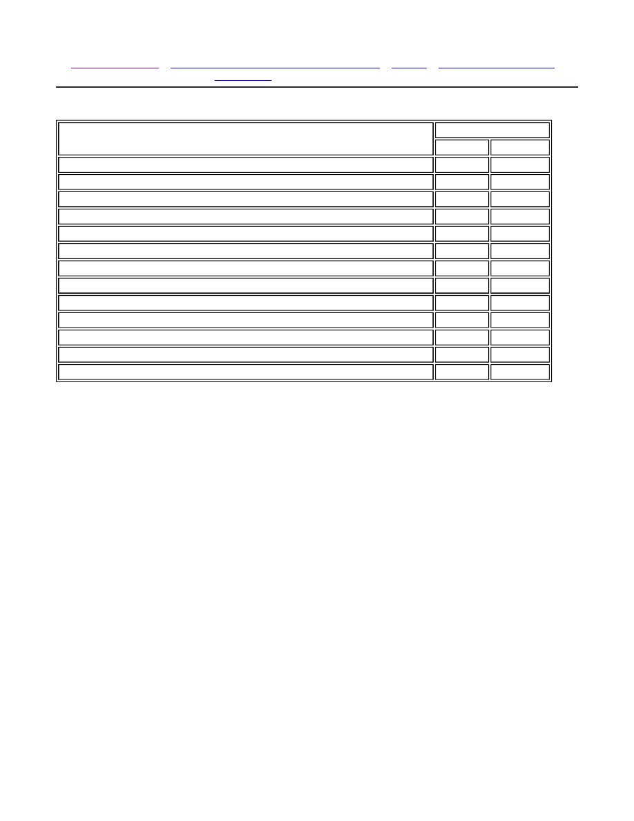
Fastener Tightening Specifications
Application
Specification
Metric
English
Coupling Flange Pinch Bolt
22 N·m
16 lb ft
Ignition Switch Housing Sheer Bolts
11 N·m
97 lb in
Ignition Switch Retaining Screw
2 N·m
18 lb in
Key Interlock Solenoid Screws
2 N·m
18 lb in
Key Reminder Switch Screws
2 N·m
18 lb in
Lower Instrument Trim Panel Screws
3 N·m
27 lb in
Lower Steering Column Cover Panel Screws
3 N·m
27 lb in
Steering Column Jacket Assembly Bracket Nuts
22 N·m
16 lb ft
Steering Wheel Nut
38 N·m
28 lb ft
Support Housing Screws
16 N·m
12 lb ft
Tilt Steering Lever Cap Screw
4 N·m
35 lb in
Turn Signal Switch Housing Screws
3 N·m
27 lb in
Upper and Lower Steering Column Cover Panel Screws
3 N·m
27 lb in
© 2010 General Motors Corporation. All rights reserved.
Page 1 of 1
Document ID: 1283590
7/6/2010
http://localhost:9001/si/showDoc.do?docSyskey=1283590&pubCellSyskey=58777&pubObj...
2008 Chevrolet Aveo
|
Aveo, Wave, G3, Barina (VIN S/T) Service Manual
|
Steering
|
Steering Wheel and Column
|
Repair Instructions
| Document ID: 1736462
Turn Signal Multifunction Switch Replacement
(Notchback)
Removal Procedure
1. Disconnect the negative battery cable. Refer to
Battery Negative Cable Disconnection and
Connection
.
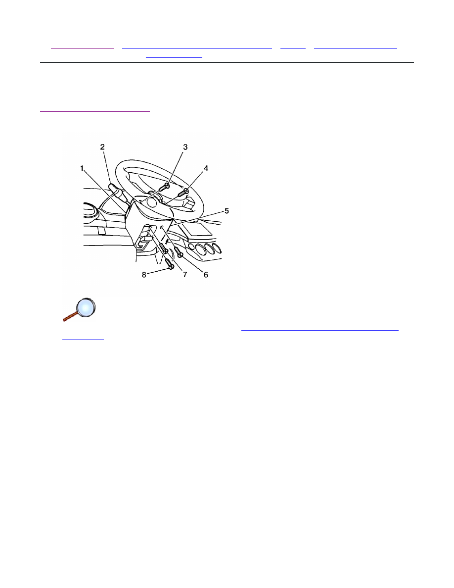
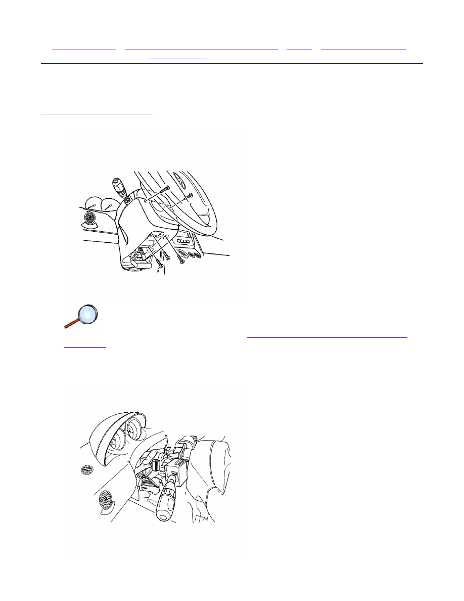
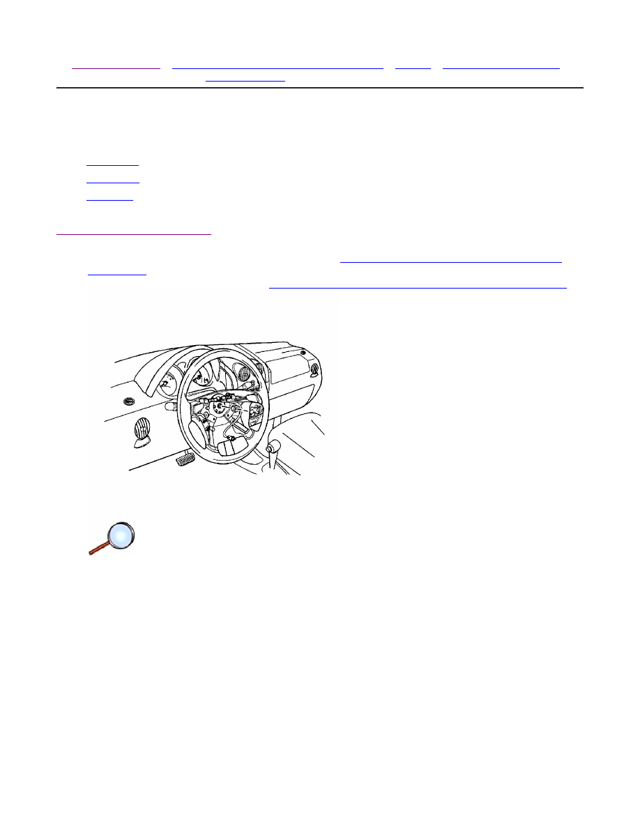
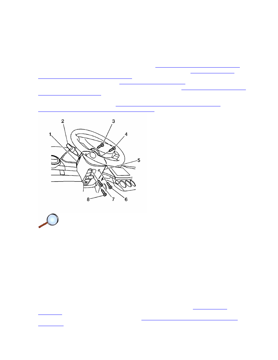
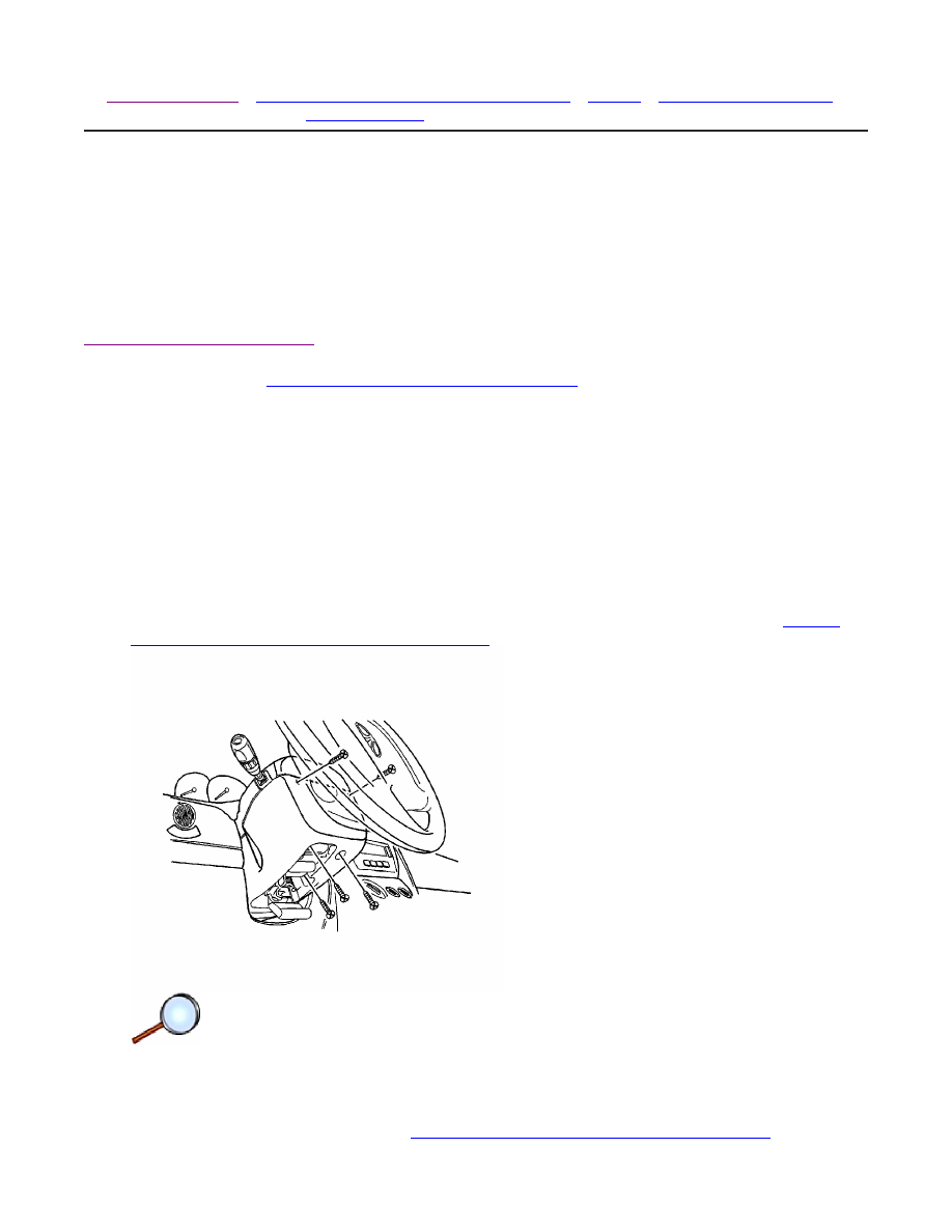
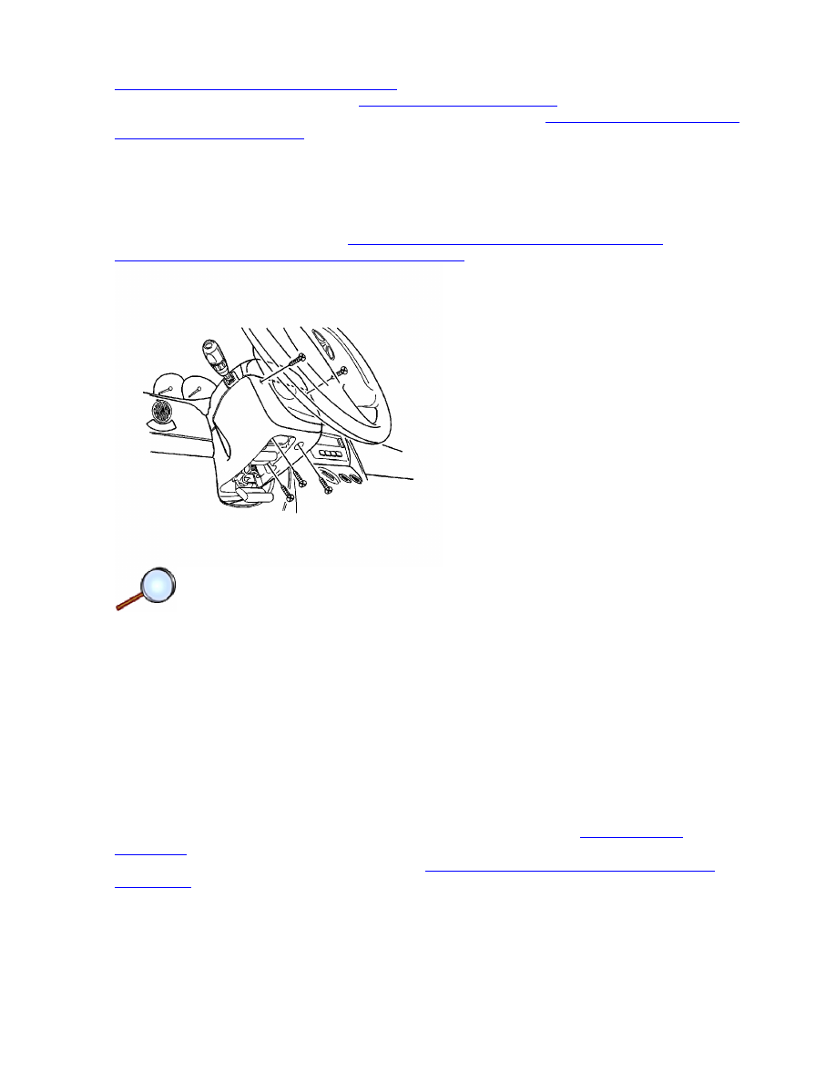
2. Remove the lower steering column cover panel screws (6, 7, 8).
3. Turn the steering wheel in order to access the upper steering column cover panel
screws (3, 4). Remove the upper steering column cover panel screws.
4. Remove the upper steering column cover panel (1) and the lower steering column cover
panel (5).
© 2010 General Motors Corporation. All rights reserved.
Page 1 of 3
Document ID: 1736462
7/6/2010
http://localhost:9001/si/showDoc.do?docSyskey=1736462&pubCellSyskey=67705&pubObj...
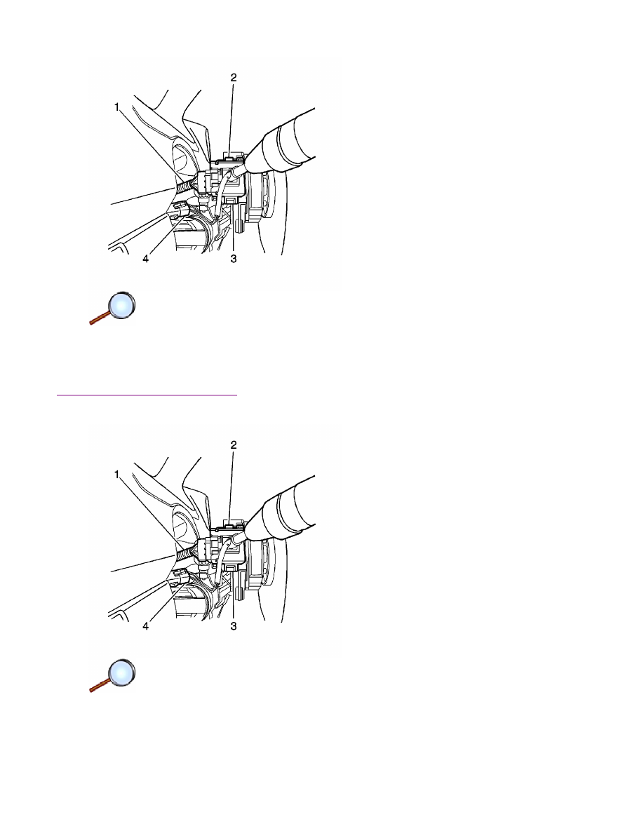
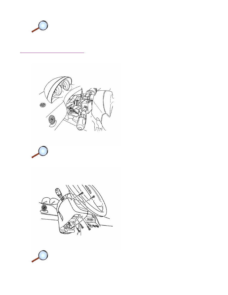
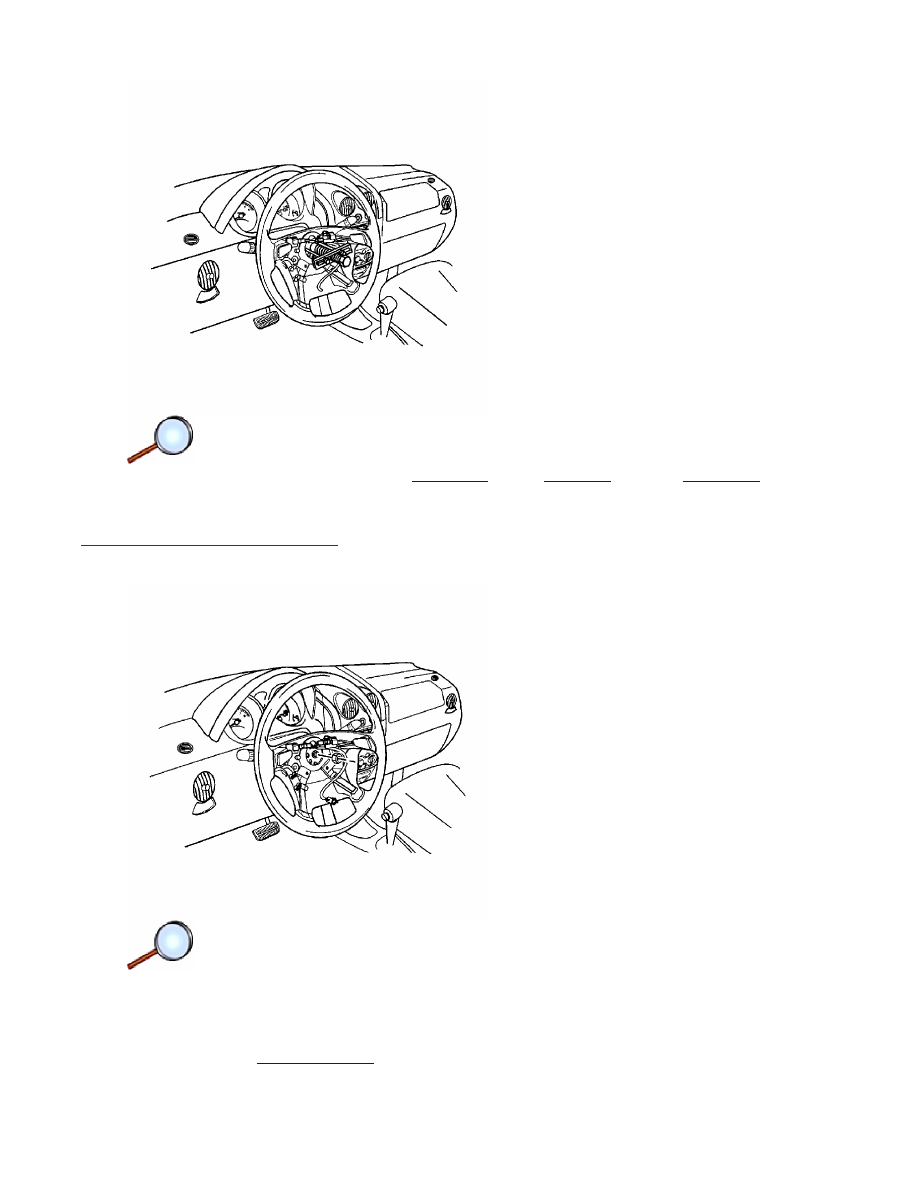
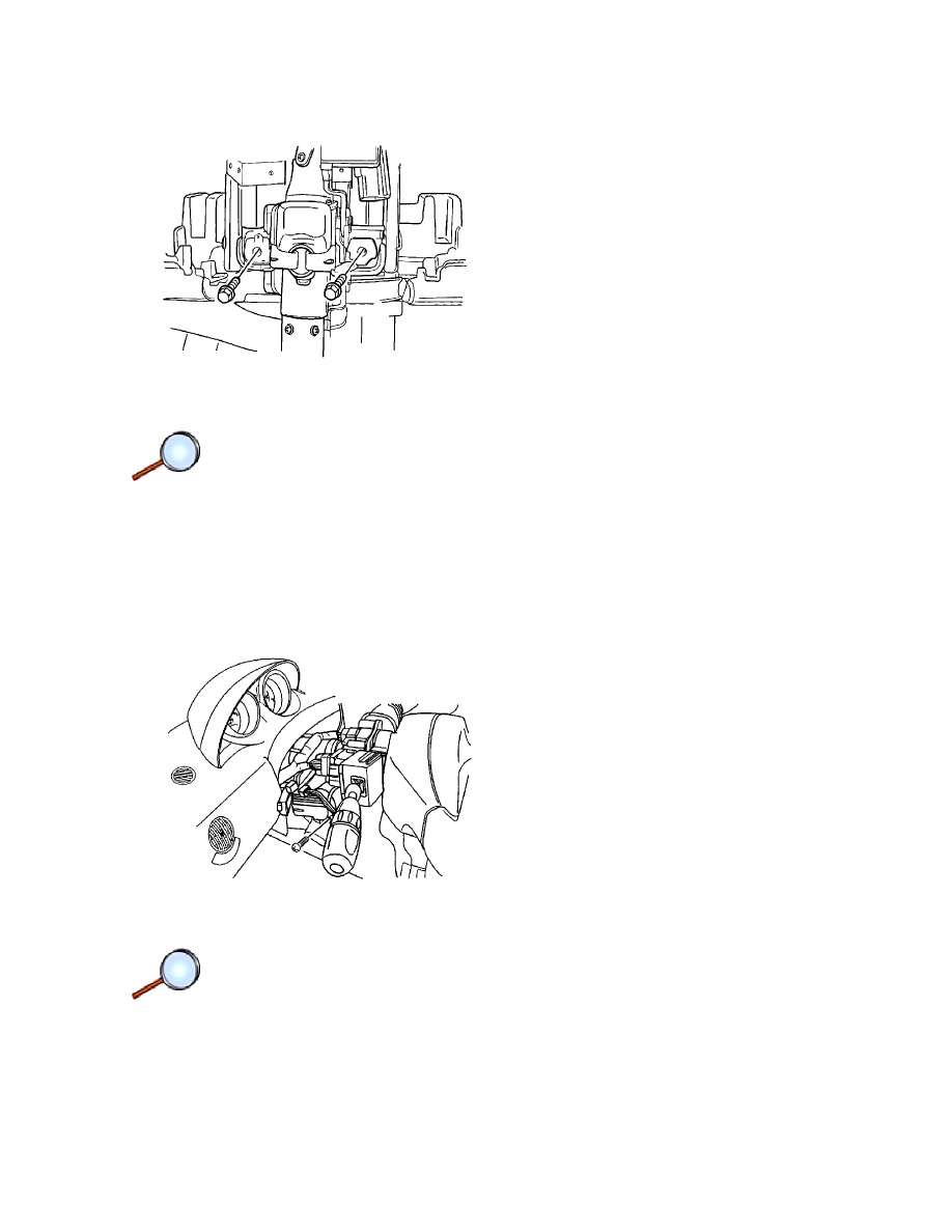
5. Remove the turn signal switch by pushing in on the tabs (2, 3) on either side of the switch
housing.
6. Disconnect the electrical connectors (1, 4) from the turn signal switch.
Installation Procedure
1. Connect the electrical connectors (1, 4) to the turn signal switch.
2. Install the turn signal switch into the switch housing.
Page 2 of 3
Document ID: 1736462
7/6/2010
http://localhost:9001/si/showDoc.do?docSyskey=1736462&pubCellSyskey=67705&pubObj...
3. Install the upper steering column cover panel (1) and the lower steering column cover
panel (5).
Notice:
Refer to
Fastener Notice
in the Preface section.
4. Install the lower steering column cover panel screws (6, 7, 8).
Tighten
Tighten the lower steering column cover panel screws to 3 N·m (27 lb in).
5. Turn the steering wheel in order to access the upper steering column cover panel screw
holes. Install the upper steering column cover panel screws (3, 4).
Tighten
Tighten the upper steering column cover panel screws to 3 N·m (27 lb in).
6. Connect the negative battery cable. Refer to
Battery Negative Cable Disconnection and
Connection
.
Page 3 of 3
Document ID: 1736462
7/6/2010
http://localhost:9001/si/showDoc.do?docSyskey=1736462&pubCellSyskey=67705&pubObj...
2008 Chevrolet Aveo
|
Aveo, Wave, G3, Barina (VIN S/T) Service Manual
|
Steering
|
Steering Wheel and Column
|
Repair Instructions
| Document ID: 1878992
Turn Signal Multifunction Switch Replacement
(Hatchback)
Removal Procedure
1. Disconnect the negative battery cable. Refer to
Battery Negative Cable Disconnection and
Connection
.
2. Remove the lower steering column cover panel screws.
3. Turn the steering wheel in order to access the upper steering column cover panel screws.
Remove the upper steering column cover panel screws.
4. Remove the upper and the lower steering column cover panels.
© 2010 General Motors Corporation. All rights reserved.
Page 1 of 3
Document ID: 1878992
7/6/2010
http://localhost:9001/si/showDoc.do?docSyskey=1878992&pubCellSyskey=67705&pubObj...
5. Remove the turn signal switch by pushing in on the tabs on either side of the switch housing.
6. Disconnect the electrical connectors from the turn signal switch.
Installation Procedure
1. Connect the electrical connectors to the turn signal switch.
2. Install the turn signal switch into the switch housing.
3. Install the upper and the lower steering column cover panels.
Page 2 of 3
Document ID: 1878992
7/6/2010
http://localhost:9001/si/showDoc.do?docSyskey=1878992&pubCellSyskey=67705&pubObj...

Notice:
Refer to
Fastener Notice
in the Preface section.
4. Install the lower steering column cover panel screws.
Tighten
Tighten the lower steering column cover panel screws to 3 N·m (27 lb in).
5. Turn the steering wheel in order to access the upper steering column cover panel screw
holes. Install the upper steering column cover panel screws.
Tighten
Tighten the upper steering column cover panel screws to 3 N·m (27 lb in).
6. Connect the negative battery cable. Refer to
Battery Negative Cable Disconnection and
Connection
.
Page 3 of 3
Document ID: 1878992
7/6/2010
http://localhost:9001/si/showDoc.do?docSyskey=1878992&pubCellSyskey=67705&pubObj...
2008 Chevrolet Aveo
|
Aveo, Wave, G3, Barina (VIN S/T) Service Manual
|
Steering
|
Steering Wheel and Column
|
Repair Instructions
| Document ID: 1736464
Steering Wheel Replacement (Notchback)
Tools Required
KM-210-A
Steering Wheel Puller
Removal Procedure
1. Disconnect the negative battery cable. Refer to
Battery Negative Cable Disconnection and
Connection
.
2. Remove the SIR module. Refer to
Inflatable Restraint Steering Wheel Module Replacement
.
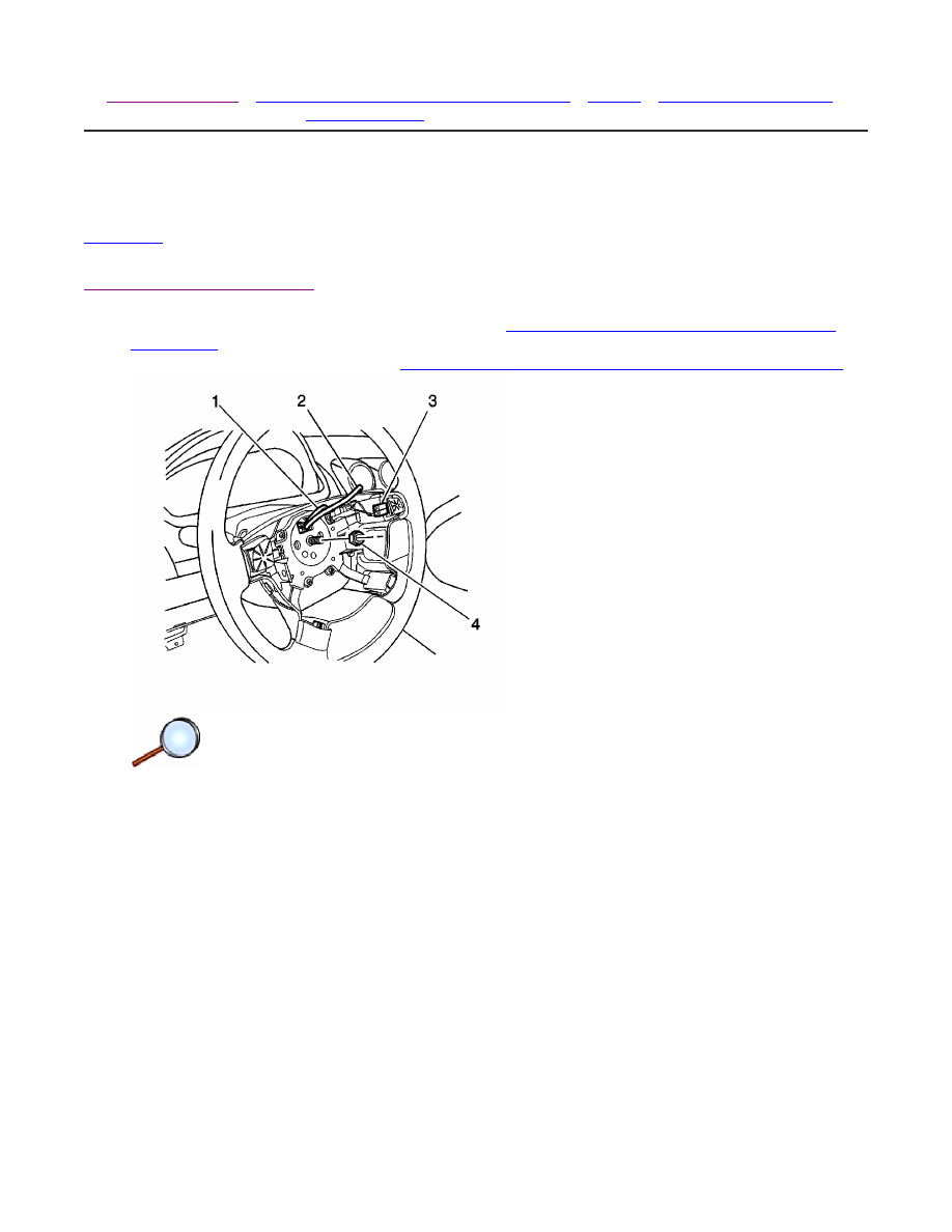
3. Place match marks on the steering wheel and on the steering column shaft.
4. Disconnect the horn connector.
5. Remove the steering wheel nut (4) and the retaining clip.
© 2010 General Motors Corporation. All rights reserved.
Page 1 of 3
Document ID: 1736464
7/6/2010
http://localhost:9001/si/showDoc.do?docSyskey=1736464&pubCellSyskey=58813&pubObj...
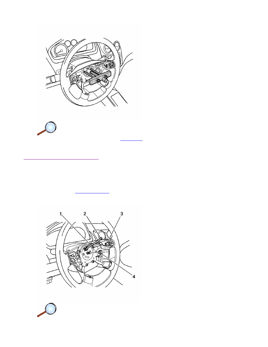
6. Remove the steering wheel using the
KM-210-A
.
7. Unclip the contact ring from the steering wheel, if necessary.
Installation Procedure
1. Clip the contact ring on the steering wheel, if necessary.
2. Align the match marks on the steering wheel and the steering column shaft. Turn the signal-
canceling cam on the wheel to the left.
Notice:
Refer to
Fastener Notice
in the Preface section.
3. Install the retaining clip and the steering wheel nut (4).
Page 2 of 3
Document ID: 1736464
7/6/2010
http://localhost:9001/si/showDoc.do?docSyskey=1736464&pubCellSyskey=58813&pubObj...

Tighten
Tighten the steering wheel nut to 38 N·m (28 lb ft).
4. Bend the tabs to secure the retaining clip.
5. Install the SIR module. Refer to
Inflatable Restraint Steering Wheel Module Replacement
.
6. Connect the negative battery cable. Refer to
Battery Negative Cable Disconnection and
Connection
.
Page 3 of 3
Document ID: 1736464
7/6/2010
http://localhost:9001/si/showDoc.do?docSyskey=1736464&pubCellSyskey=58813&pubObj...
2008 Chevrolet Aveo
|
Aveo, Wave, G3, Barina (VIN S/T) Service Manual
|
Steering
|
Steering Wheel and Column
|
Repair Instructions
| Document ID: 1878999
Steering Wheel Replacement (Hatchback)
Tools Required
Removal Procedure
1. Disconnect the negative battery cable. Refer to
Battery Negative Cable Disconnection and
Connection
.
2. Remove the SIR module. Refer to
Inflatable Restraint Steering Wheel Module Replacement
.
3. Place match marks on the steering wheel and on the steering column shaft.
4. Remove the steering wheel nut and the retaining clip.
•
KM-210-A
Steering Wheel Puller
•
J 36541-A
Steering Wheel Puller Legs
•
J 1859-A
Steering Wheel Puller
© 2010 General Motors Corporation. All rights reserved.
Page 1 of 3
Document ID: 1878999
7/6/2010
http://localhost:9001/si/showDoc.do?docSyskey=1878999&pubCellSyskey=58813&pubObj...
5. Remove the steering wheel using the
KM-210-A
or the
J 1859-A
with the
J 36541-A
.
6. Unclip the contact ring from the steering wheel, if necessary.
Installation Procedure
1. Clip the contact ring on the steering wheel, if necessary.
2. Align the match marks on the steering wheel and the steering column shaft. Turn the signal-
canceling cam on the wheel to the left.
Notice:
Refer to
Fastener Notice
in the Preface section.
3. Install the retaining clip and the steering wheel nut.
Page 2 of 3
Document ID: 1878999
7/6/2010
http://localhost:9001/si/showDoc.do?docSyskey=1878999&pubCellSyskey=58813&pubObj...

Tighten
Tighten the steering wheel nut to 38 N·m (28 lb ft).
4. Bend the tabs to secure the retaining clip.
5. Install the SIR module. Refer to
Inflatable Restraint Steering Wheel Module Replacement
.
6. Connect the negative battery cable. Refer to
Battery Negative Cable Disconnection and
Connection
.
Page 3 of 3
Document ID: 1878999
7/6/2010
http://localhost:9001/si/showDoc.do?docSyskey=1878999&pubCellSyskey=58813&pubObj...
2008 Chevrolet Aveo
|
Aveo, Wave, G3, Barina (VIN S/T) Service Manual
|
Steering
|
Steering Wheel and Column
|
Repair Instructions
| Document ID: 1736471
Steering Column Replacement (Notchback)
Important: Remove the steering column only if:
Removal Procedure
Notice:
Refer to
Steering Column in Lock Position Notice
in the Preface section.
Important: Ensure the front wheels are in the straight-ahead position.
1. Adjust the steering wheel to the straight-ahead position.
Caution: The sensing and the diagnosis module (SDM) can maintain sufficient voltage to
deploy the airbags and pretensioners for up to 1 minute after the ignition has been turned
OFF and the fuse has been removed. If the airbags and pretensioners are not disconnected,
do not begin service until one minute has been passed after disconnecting power to the SDM.
Failure to do so may cause personal injury.
2. Disconnect the negative battery cable and let the vehicle sit for 1 minute. Refer to
Battery
Negative Cable Disconnection and Connection
.
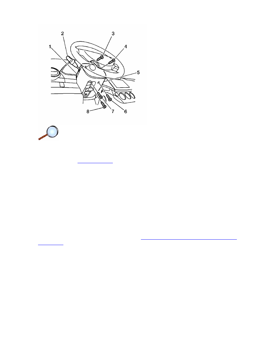
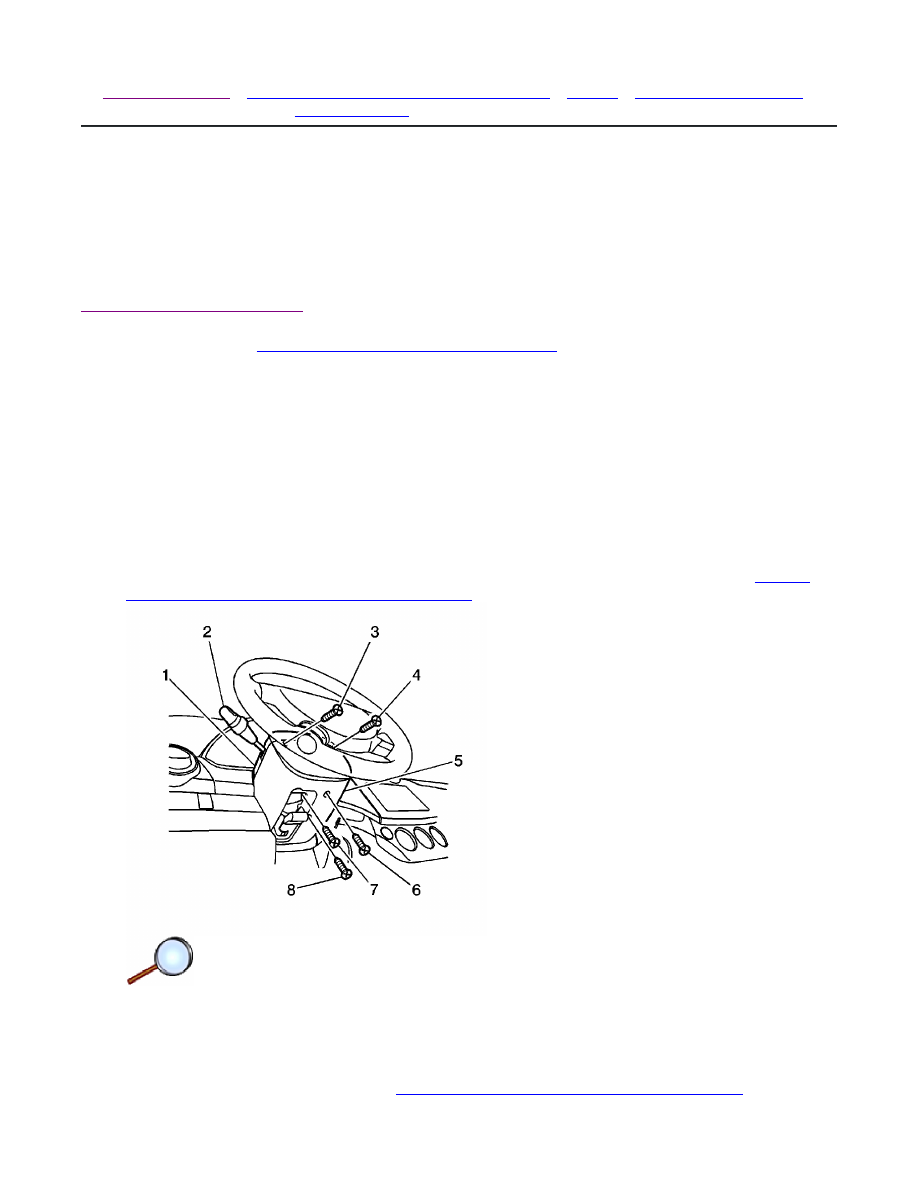
3. Remove the lower steering column cover panel screws (6, 7, 8).
4. Turn the steering wheel in order to access the upper steering column cover panel screws (3,
4). Remove the upper steering column cover panel screws.
5. Remove the upper steering column cover panel (1) and the lower steering column cover
panel (5).
6. Remove the switch levers. Refer to
Turn Signal Multifunction Switch Replacement
and to
• The steering column requires replacement.
• The steering and the ignition lock housing require replacement.
• Another operation requires the removal of the steering column.
© 2010 General Motors Corporation. All rights reserved.
Page 1 of 6
Document ID: 1736471
7/6/2010
http://localhost:9001/si/showDoc.do?docSyskey=1736471&pubCellSyskey=58809&pubObj...
Windshield Wiper and Washer Switch Replacement
.
7. Using a taped flat-bladed tool, gently pry and remove the instrument panel lower cover in
order to access the steering column.
8. Remove the inflatable restraint steering wheel module. Refer to
Inflatable Restraint Steering
Wheel Module Replacement
.
9. Remove the steering wheel. Refer to
Steering Wheel Replacement
.
10. Remove the inflatable restraint steering wheel module coil. Refer to
Inflatable Restraint
Steering Wheel Module Coil Replacement
.
11. Remove the theft deterrent control module. Refer to
Theft Deterrent Module Replacement
.
12. Remove the following components. Refer to
Ignition Lock Cylinder Replacement
.
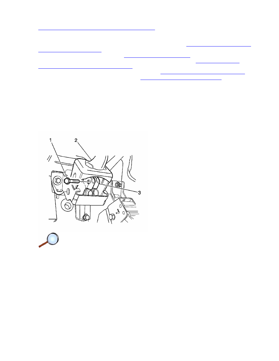
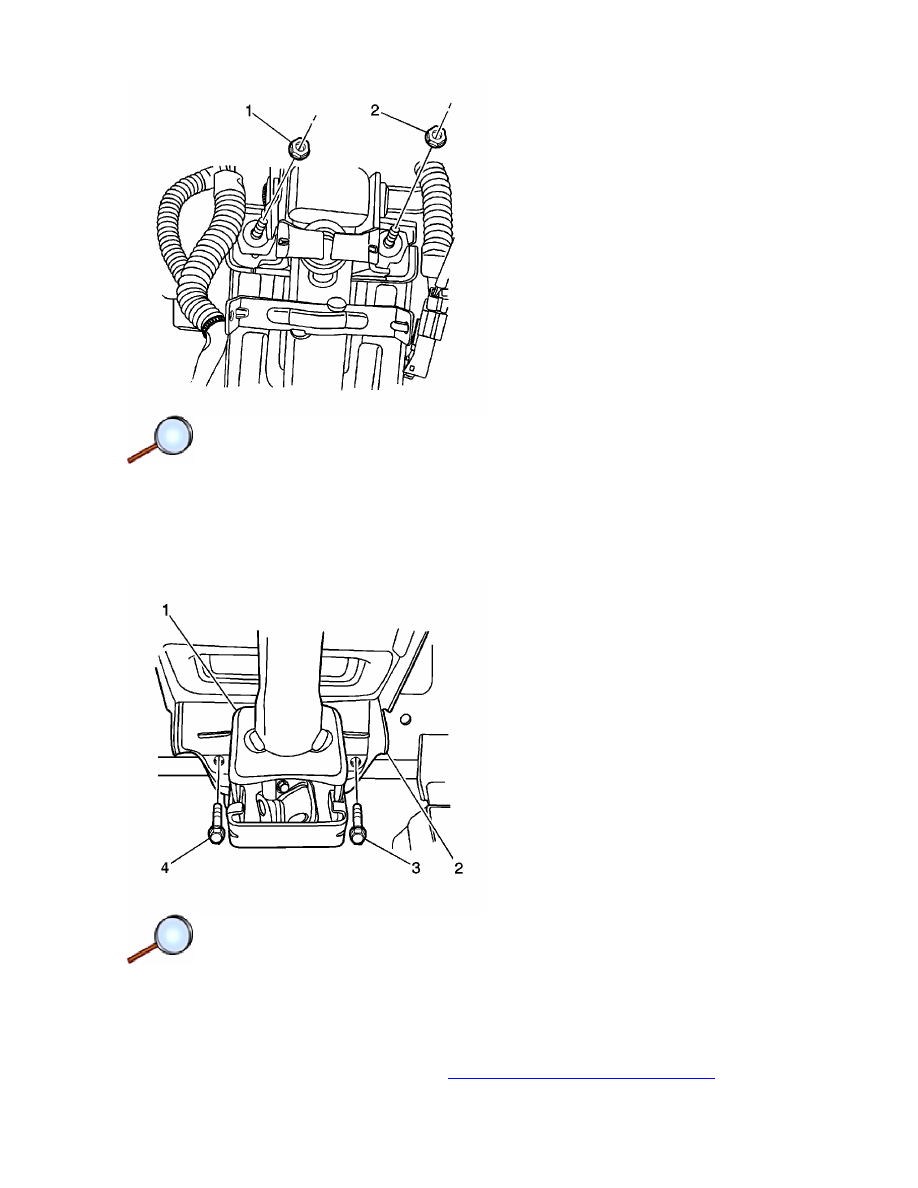
13. Remove the pinch bolt (1) from the upper steering shaft coupling flange (3).
12.1. The key reminder switch screws
12.2. The key reminder switch
12.3. The key hole illumination screw
12.4. The key hole illumination
12.5. The ignition switch
12.6. The ignition lock cylinder
Page 2 of 6
Document ID: 1736471
7/6/2010
http://localhost:9001/si/showDoc.do?docSyskey=1736471&pubCellSyskey=58809&pubObj...
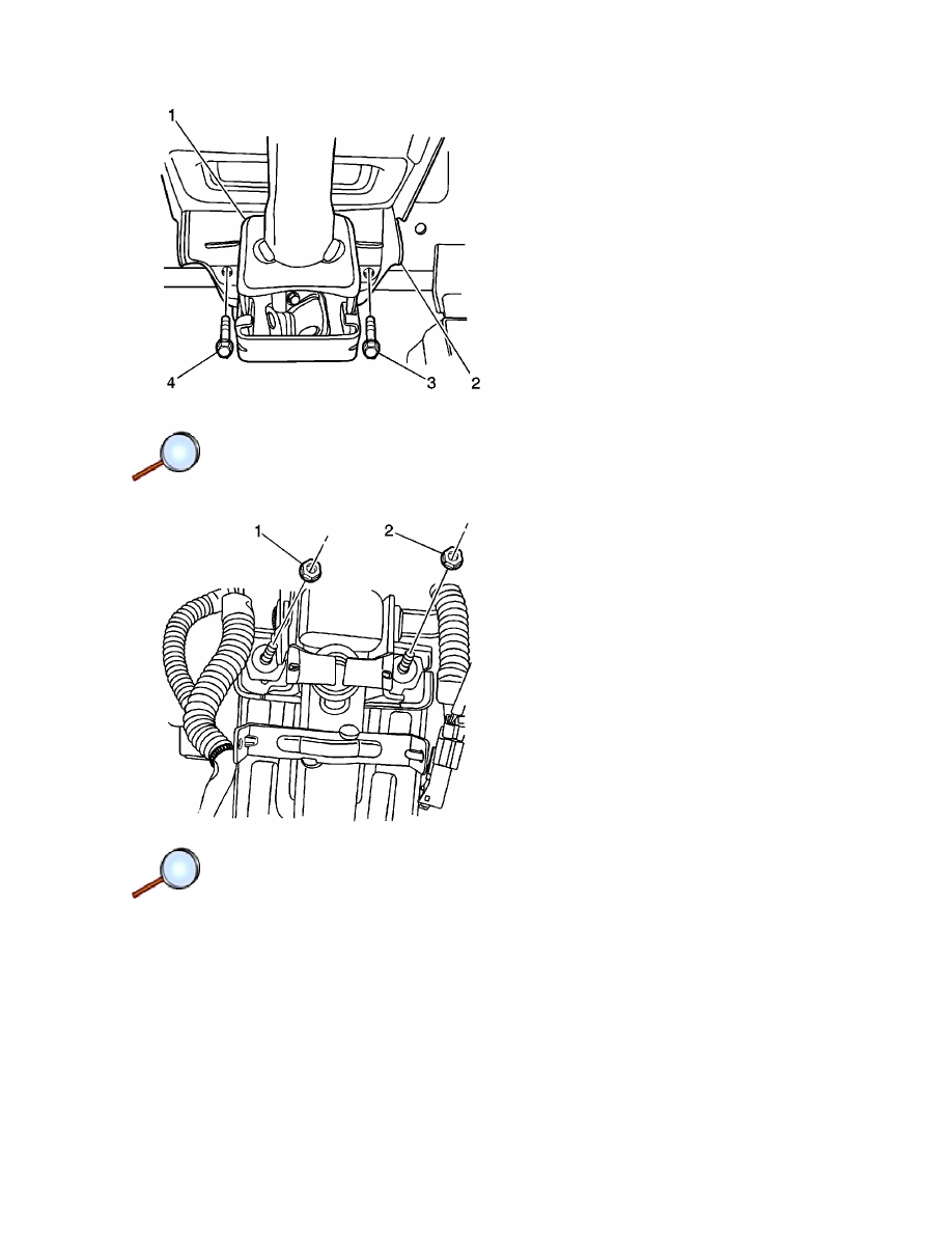
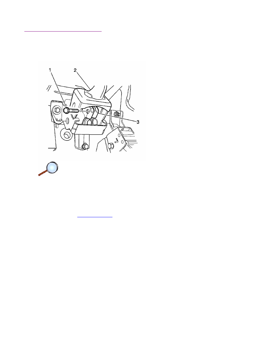
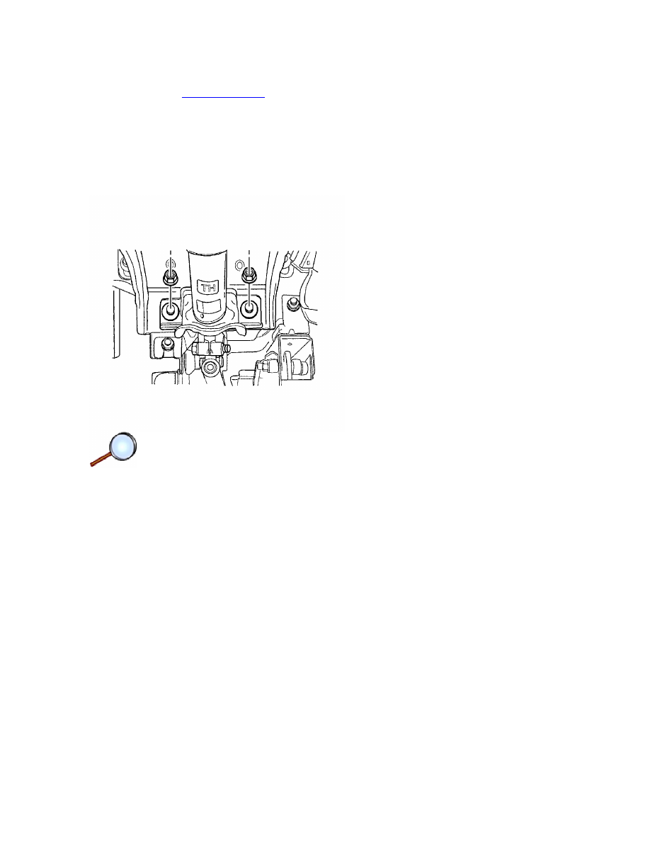
14. Remove the bolts (3, 4) holding the steering column jacket assembly lower bracket.
15. Remove the nuts (1, 2) holding the steering column jacket assembly upper bracket.
Notice: Once the steering column is removed from the vehicle, the column is extremely
susceptible to damage. Dropping the column assembly on the end could collapse the steering
shaft or loosen the plastic injections, which maintain column rigidity. Leaning on the column
assembly could cause the jacket to bend or deform. Any of the above damage could impair
the columns collapsible design. Do NOT hammer on the end of the shaft, because hammering
could loosen the plastic injections, which maintain column rigidity. If you need to remove the
steering wheel, refer to the Steering Wheel Replacement procedure in this section.
16. Guide the steering column assembly out of the steering shaft flange and carefully lay down
the assembly.
Page 3 of 6
Document ID: 1736471
7/6/2010
http://localhost:9001/si/showDoc.do?docSyskey=1736471&pubCellSyskey=58809&pubObj...
Installation Procedure
Important: For proper installation of the steering column, ensure the front wheels are in the
straight-ahead position.
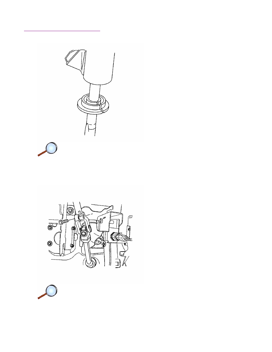
1. Place the alignment bushing onto the end of the steering column shaft.
Important: Provide support for the steering column assembly until the mounting nuts are
fastened. Do not let the steering column assembly hang unsupported.
2. Carefully guide the steering shaft into the steering shaft coupling flange (3).
Notice:
Refer to
Fastener Notice
in the Preface section.
3. Install the pinch bolt (1) into the non-threaded hole of the flange.
Tighten
Tighten the pinch bolt to 22 N·m (16 lb ft).
4. Slide the alignment bushing into the steering column housing.
Page 4 of 6
Document ID: 1736471
7/6/2010
http://localhost:9001/si/showDoc.do?docSyskey=1736471&pubCellSyskey=58809&pubObj...
5. Install the nuts (1, 2) to the of the steering column jacket assembly front bracket.
Tighten
Tighten the nuts to 22 N·m (16 lb ft).
6. Install the bolts (3, 4) to the rear bracket of the steering column jacket assembly.
Tighten
Tighten the bolts to 22 N·m (16 lb ft).
7. Install the following components. Refer to
Ignition Lock Cylinder Replacement
.
7.1. The ignition lock cylinder
Page 5 of 6
Document ID: 1736471
7/6/2010
http://localhost:9001/si/showDoc.do?docSyskey=1736471&pubCellSyskey=58809&pubObj...
8. Install the theft deterrent control module. Refer to
Theft Deterrent Module Replacement
.
9. Install the inflatable restraint steering wheel module coil. Refer to
Inflatable Restraint
Steering Wheel Module Coil Replacement
.
10. Install the steering wheel. Refer to
Steering Wheel Replacement
.
11. Install the inflatable restraint steering wheel module. Refer to
Inflatable Restraint Steering
Wheel Module Replacement
.
12. Install the instrument panel lower cover.
13. Install the switch levers. Refer to
Turn Signal Multifunction Switch Replacement
and to
Windshield Wiper and Washer Switch Replacement
.
14. Install the upper steering column cover panel (1) and the lower steering column cover
panel (5).
15. Install the lower steering column cover panel screws (6, 7, 8).
Tighten
Tighten the lower steering column cover panel screws to 3 N·m (27 lb in).
16. Turn the steering wheel in order to access the upper steering column cover panel screw
holes. Install the upper steering column cover panel screws (3, 4).
Tighten
Tighten the upper steering column cover panel screws to 3 N·m (27 lb in).
17. Verify the steering wheel is in the straight-ahead position. Refer to
Straight Ahead
Inspection
.
18. Connect the negative battery cable. Refer to
Battery Negative Cable Disconnection and
Connection
.
7.2. The ignition switch
7.3. The key hole illumination
7.4. The key hole illumination screw
7.5. The key reminder switch
7.6. The key reminder switch screws
Page 6 of 6
Document ID: 1736471
7/6/2010
http://localhost:9001/si/showDoc.do?docSyskey=1736471&pubCellSyskey=58809&pubObj...
2008 Chevrolet Aveo
|
Aveo, Wave, G3, Barina (VIN S/T) Service Manual
|
Steering
|
Steering Wheel and Column
|
Repair Instructions
| Document ID: 1879273
Steering Column Replacement (Hatchback)
Important: Remove the steering column only if:
Removal Procedure
Notice:
Refer to
Steering Column in Lock Position Notice
in the Preface section.
Important: Ensure the front wheels are in the straight-ahead position.
1. Adjust the steering wheel to the straight-ahead position.
Caution: The sensing and the diagnosis module (SDM) can maintain sufficient voltage to
deploy the airbags and pretensioners for up to 1 minute after the ignition has been turned
OFF and the fuse has been removed. If the airbags and pretensioners are not disconnected,
do not begin service until one minute has been passed after disconnecting power to the SDM.
Failure to do so may cause personal injury.
2. Disconnect the negative battery cable and let the vehicle sit for 1 minute. Refer to
Battery
Negative Cable Disconnection and Connection
.
3. Remove the lower steering column cover panel screws.
4. Turn the steering wheel in order to access the upper steering column cover panel screws.
Remove the upper steering column cover panel screws.
5. Remove the upper steering column cover panel and the lower steering column cover panel.
6. Remove the switch levers. Refer to
Turn Signal Multifunction Switch Replacement
and to
• The steering column requires replacement.
• The steering and the ignition lock housing require replacement.
• Another operation requires the removal of the steering column.
© 2010 General Motors Corporation. All rights reserved.
Page 1 of 9
Document ID: 1879273
7/6/2010
http://localhost:9001/si/showDoc.do?docSyskey=1879273&pubCellSyskey=58809&pubObj...
Windshield Wiper and Washer Switch Replacement
.
7. Remove the screws and the lower instrument trim panel.
8. Remove the inflatable restraint steering wheel module. Refer to
Inflatable Restraint Steering
Wheel Module Replacement
.
9. Remove the steering wheel. Refer to
Steering Wheel Replacement
.
10. Remove the inflatable restraint steering wheel module coil. Refer to
Inflatable Restraint
Steering Wheel Module Coil Replacement
.
11. Remove the theft deterrent control module. Refer to
Theft Deterrent Module Replacement
.
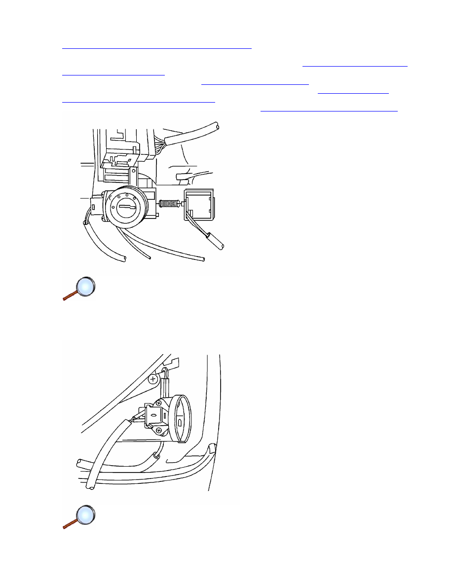
Important: Do not drop the key interlock solenoid spring.
12. Remove the key interlock solenoid screws and the key interlock solenoid.
13. Remove the key reminder switch screws and the key reminder switch.
Page 2 of 9
Document ID: 1879273
7/6/2010
http://localhost:9001/si/showDoc.do?docSyskey=1879273&pubCellSyskey=58809&pubObj...
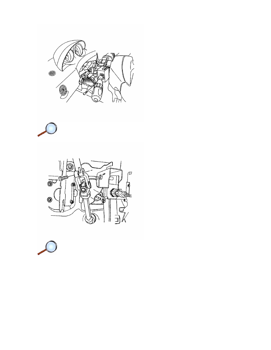
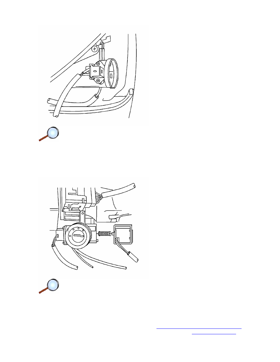
14. Disconnect the ignition switch electrical connector.
15. Remove the pinch bolt from the upper steering shaft coupling flange.
Page 3 of 9
Document ID: 1879273
7/6/2010
http://localhost:9001/si/showDoc.do?docSyskey=1879273&pubCellSyskey=58809&pubObj...
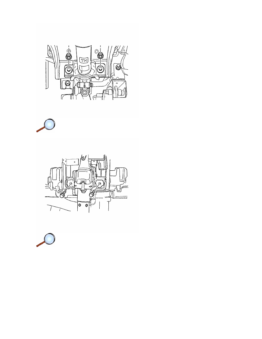
16. Remove the nuts holding the steering column jacket assembly rear bracket.
17. Remove the bolts holding the steering column jacket assembly front bracket.
Notice: Once the steering column is removed from the vehicle, the column is extremely
susceptible to damage. Dropping the column assembly on the end could collapse the steering
shaft or loosen the plastic injections, which maintain column rigidity. Leaning on the column
assembly could cause the jacket to bend or deform. Any of the above damage could impair
the columns collapsible design. Do NOT hammer on the end of the shaft, because hammering
could loosen the plastic injections, which maintain column rigidity. If you need to remove the
steering wheel, refer to the Steering Wheel Replacement procedure in this section.
18. Guide the steering column assembly out of the steering shaft flange and carefully lay down
the assembly.
Page 4 of 9
Document ID: 1879273
7/6/2010
http://localhost:9001/si/showDoc.do?docSyskey=1879273&pubCellSyskey=58809&pubObj...
Installation Procedure
Important: For proper installation of the steering column, ensure the front wheels are in the
straight-ahead position.
1. Place the alignment bushing onto the end of the steering column shaft.
Important: Provide support for the steering column assembly until the mounting nuts are
fastened. Do not let the steering column assembly hang unsupported.
Page 5 of 9
Document ID: 1879273
7/6/2010
http://localhost:9001/si/showDoc.do?docSyskey=1879273&pubCellSyskey=58809&pubObj...
2. Carefully guide the steering shaft into the coupling flange.
Notice:
Refer to
Fastener Notice
in the Preface section.
3. Install the pinch bolt into the non-threaded hole of the flange.
Tighten
Tighten the pinch bolt to 22 N·m (16 lb ft).
4. Slide the alignment bushing into the steering column housing.
5. Install the nuts for the rear bracket of the steering column jacket assembly.
Tighten
Tighten the nuts to 22 N·m (16 lb ft).
Page 6 of 9
Document ID: 1879273
7/6/2010
http://localhost:9001/si/showDoc.do?docSyskey=1879273&pubCellSyskey=58809&pubObj...
6. Install the bolts for the steering column jacket assembly front bracket.
Tighten
Tighten the bolts to 22 N·m (16 lb ft).
7. Connect the ignition switch electrical connector.
Page 7 of 9
Document ID: 1879273
7/6/2010
http://localhost:9001/si/showDoc.do?docSyskey=1879273&pubCellSyskey=58809&pubObj...
8. Install the key reminder switch and the key reminder switch screws.
Tighten
Tighten the screws to 2 N·m (18 lb in).
9. Install the key interlock solenoid and the key interlock solenoid screws.
Tighten
Tighten the screws to 2 N·m (18 lb in).
10. Install the theft deterrent control module. Refer to
Theft Deterrent Module Replacement
.
11. Install the inflatable restraint steering wheel module coil. Refer to
Inflatable Restraint
Page 8 of 9
Document ID: 1879273
7/6/2010
http://localhost:9001/si/showDoc.do?docSyskey=1879273&pubCellSyskey=58809&pubObj...
Steering Wheel Module Coil Replacement
.
12. Install the steering wheel. Refer to
Steering Wheel Replacement
.
13. Install the inflatable restraint steering wheel module. Refer to
Inflatable Restraint Steering
Wheel Module Replacement
.
14. Install the lower instrument trim panel and the screws.
Tighten
Tighten the screws to 3 N·m (27 lb in).
15. Install the switch levers. Refer to
Turn Signal Multifunction Switch Replacement
and to
Windshield Wiper and Washer Switch Replacement
.
16. Install the upper steering column cover panel and the lower steering column cover panel.
17. Install the lower steering column cover panel screws.
Tighten
Tighten the lower steering column cover panel screws to 3 N·m (27 lb in).
18. Turn the steering wheel in order to access the upper steering column cover panel screw
holes. Install the upper steering column cover panel screws.
Tighten
Tighten the upper steering column cover panel screws to 3 N·m (27 lb in).
19. Verify the steering wheel is in the straight-ahead position. Refer to
Straight Ahead
Inspection
.
20. Connect the negative battery cable. Refer to
Battery Negative Cable Disconnection and
Connection
.
Page 9 of 9
Document ID: 1879273
7/6/2010
http://localhost:9001/si/showDoc.do?docSyskey=1879273&pubCellSyskey=58809&pubObj...
Document Outline
Wyszukiwarka
Podobne podstrony:
M36e Steering Wheel and Column
28 Wheel and Tire
28 Wheel and Tire System Inspection
Audi A4 Multi function steering wheel 2001
G 2 0 DOHC Steering Wheel System Repair doc
Hydraulic Steering Maintenance and Repair
28 Wheel and Tire System Inspection
28 Wheel and Tire
G 2 0 DOHC Steering Wheel System doc
Steering wheel Control Switch
50 Steering Column
50 Steering Column
61 STEERING COLUMN SWITCHES
Popular Mechanics Diagnosing And Repairing Wheel Vibration
50 Steering Column
11 Front Wheel Suspension Steering
60 STEERING COLUMN
50 Steering Column
więcej podobnych podstron