PCBA Debug Guide
Memory Faults
Debug Guide
Rev. 3.2
|
Página 1 de 8
Rev. 3.2
PCBA Debug Guide
1. Revision History
Revision
Description
Author/Revised
By
Date
1.0
Draft release
Luis Rodriguez
11 0ct 2005
2.0
3 Repair now include all left
memories and created
category for BGA problems
related.
José Candelario
Bravo
10 Jan 2006
2.1
Updated Category F
(Added replacement of component:
U4D1)
José Candelario
Bravo
30 Jan 2006
2.2
Replaced Category H for
Category G and deleted the
last one.
José Candelario
Bravo
10 Feb 2006
2.3
Updated Category B
(Added a new front panel error code and
the components to repair)
Luis Rodríguez
José C. Bravo
16 Feb 2006
2.3
Updated Category D
(Added replacement of components:
U4D1)
Luis Rodríguez
José C. Bravo
16 Feb 2006
2.4
Updated Category B,D,E & F
(Added replacement of component in first
repair: U4D1)
Luis Rodríguez
José C. Bravo
16 Mar 2006
3.0
Added Category H
(Group 1
st
repair U4D1 into the category
H for the Front Panel Error Codes 0x10
to 0x15 with CPUs bits 01000000)
Luis Rodríguez
José C. Bravo
17 Mar 2006
3.1
Updated Category H
(Group 1
st
repair U4D1 into the category
H for the Front Panel Error Codes 0x10
to 0x15 with CPUs bits 10101111)
Luis Rodríguez
José C. Bravo
22 Mar 06
3.2
Updated Category H
(Added repair action for CPU bits
01110101)
Luis Rodríguez
José C. Bravo
05 April 06
Página 2 de 8
Rev. 3.2
PCBA Debug Guide
2. Table of Contents
1. Revision History ......................................................................................................... 2
2. Table of Contents........................................................................................................ 3
3. Introduction................................................................................................................. 3
4. Scope.......................................................................................................................... 3
5. Audience ..................................................................................................................... 3
6. Process ........................................................................................................................ 4
7. Category Grouping...................................................................................................... 4
7.1 Category A V_MEM voltage problem ................................................................. 4
7.2 Category B Error Code 0x10, E16........................................................................ 5
7.3 Category C Error Code 0x11, E17........................................................................ 5
7.4 Category D Error Code 0x12, E18........................................................................ 5
7.5 Category E Error Code 0x13, E19 ........................................................................ 6
7.6 Category F Error Code 0x14, E20 ........................................................................ 6
7.8 Category G Error Code 0x15 ................................................................................ 6
7.9 Category H CPUs Bits .......................................................................................... 7
3. Introduction
This document describes a process for diagnosing and repairing Memory failures
from the PCBA tester. The process and groupings below outlines possible
measurements to determine the appropriate component, for repair or
replacement. Core digital errors can also be identified by 3 of the 4 LEDs on the
“ring of light” flashing.
4. Scope
This document has been developed from experience gained on X803158-001
Xenon XDK motherboards. The failure analysis process outlined in this document
should be used in conjunction with the “Motherboard Debug Guide Development
Process” document.
5. Audience
This document is aimed at Engineers and Technicians who are performing first
pass debug of core digital failures from the XBOX360 motherboard PCBA tester.
Página 3 de 8
Rev. 3.2
PCBA Debug Guide
6. Process
Check on the Front panel the what kind of error code 0xxx shows or look at the
TV what error Exx is. The errors on the front panel are in hexadecimal and the
errors in the TV are in decimal.
7. Category Grouping
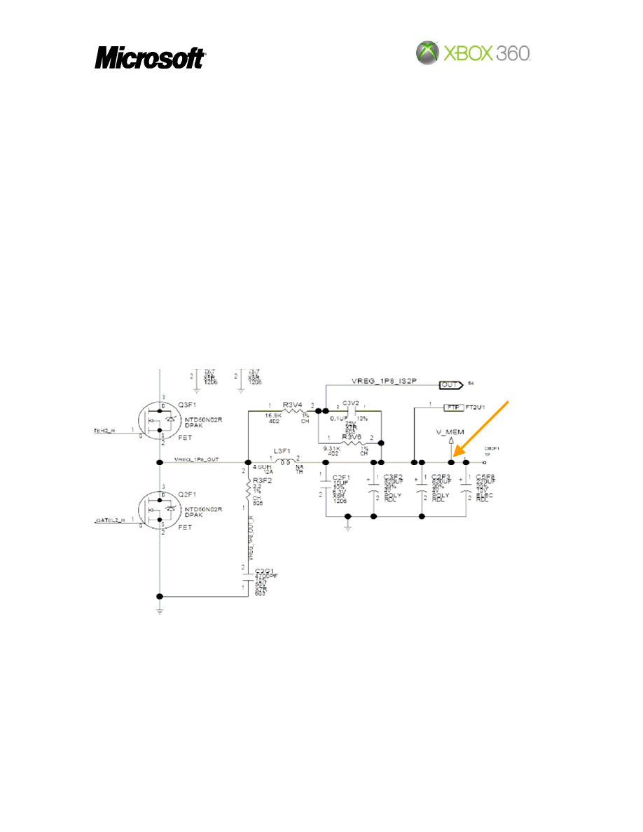
7.1 Category A V_MEM voltage problem
The SMC releases the VREG_1P8_EN_N line and enables the V_MEM controller
(U4V1).
1. Check V_MEM voltage on L3F1.2 (1.8V). If voltage is not present
• Check Q2F1 & Q3F1 for shorts, change as necessary
• Check if VREG_1P8_EN is present on U4V1.11
If is ok then change U4V1
If not present, check SB (SMC), replace as necessary
1.8v
2. Try new latest Kernel firmware
3. Replace U3D1 & U3E1 if don’t fix the problem change the mirrors (U3R1
& U3T1)
If the fail carry on then replace U4F1 & U5F1 if the problem is till present
change mirrors (U4U1 & U5U1)
Página 4 de 8
Rev. 3.2
PCBA Debug Guide
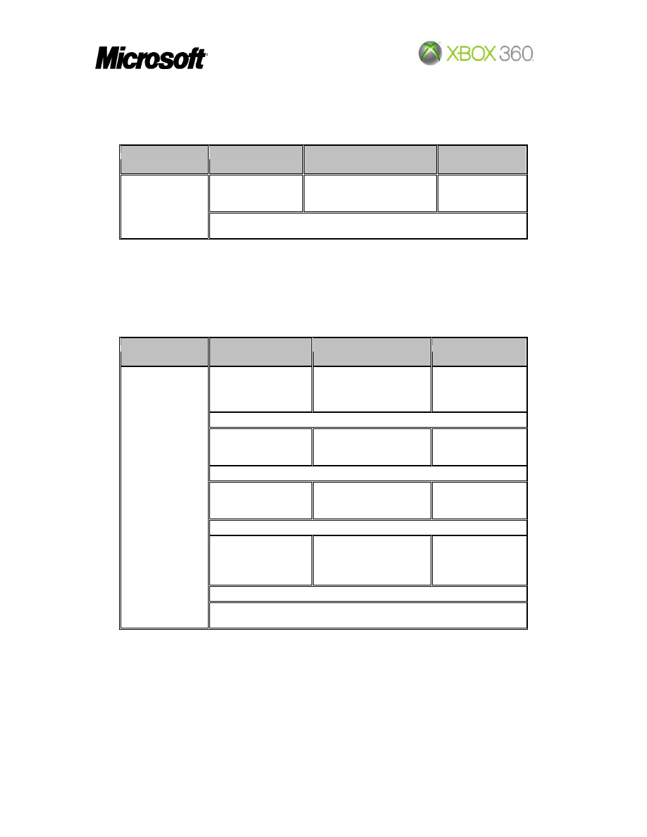
7.2 Category B Error Code 0x10, E16
ERROR_NBINIT_MEM_VENDOR_ID
Front panel Code
Bits CPU
(Decimal)
Components
Action procedure
01110111
(119)
U5F1/U5U1
U3D1/U3R1
U3E1/U3T1, 4F1/U4U1
1
st
Repair
2
nd
Repair
3
rd
Repair
0x10
For another bits refer to Category H
7.3 Category C Error Code 0x11, E17
ERROR_NBINIT_MEM_READ_STROBE_DATA_WRITE
7.4 Category D Error Code 0x12, E18
ERROR_NBINIT_MEM_READ_STROBE_DELAY_TRAINING
Front panel Code
Bits CPU
(Decimal)
Components
Action procedure
01000001
(65)
U5F1/U5U1
U3D1/U3R1
U4F1/U4U1, U5F1/U5U1
1
st
Repair
2
nd
Repair
3
rd
Repair
01000011
(67)
U3E1/U3T1
U3D1/U3R1
U4F1/U4U1, U5F1/U5U1
1
st
Repair
2
nd
Repair
3
rd
Repair
01000100
(68)
U3E1/U3T1
U3D1/U3R1
U4F1/U4U1, U5F1/U5U1
1
st
Repair
2
nd
Repair
3
rd
Repair
01110111
(119)
U5f1/U5U1
U4F1/U4U1
U3E1/U3T1, 3D1/U3R1
1st Repair
2nd Repair
3rd Repair
0x12
For another bits refer to Category H
Página 5 de 8
Rev. 3.2
PCBA Debug Guide
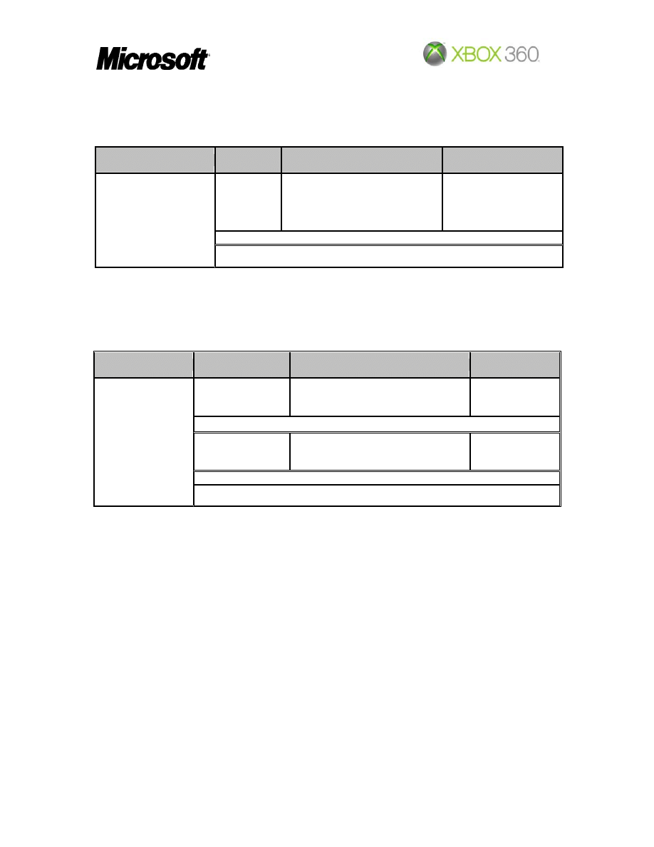
7.5 Category E Error Code 0x13, E19
ERROR_NBINIT_MEM_WRITE_STROBE_DELAY_TRAINING
Front panel Code
Bits CPU
(Decimal)
Components
Action procedure
01000100
(68)
U3D1/U3R1
U3E1/U3T1
U5F1/U5U1, U4F1/U4U1
1
st
Repair
2
nd
Repair
3
rd
Repair
0x13
For another bits refer to Category H
7.6 Category F Error Code 0x14, E20
ERROR_MEMORY_ADDRESSING
Front panel Code
Bits CPU
(Decimal)
Components
Action procedure
01000001
(65)
U4F1/U4U1
U4D1
U5F1/U5U1,U3D1/U3R1, U3E1/U3T1
1
st
Repair
2
nd
Repair
3
rd
Repair
01000010
(66)
U4F1/U4U1
U4D1
U5F1/U5U1,U3D1/U3R1, U3E1/U3T1
1
st
Repair
2
nd
Repair
3
rd
Repair
0x14
For another bits refer to Category H
7.8 Category G Error Code 0x15
ERROR_MEMORY_DATA
Página 6 de 8
Rev. 3.2
PCBA Debug Guide
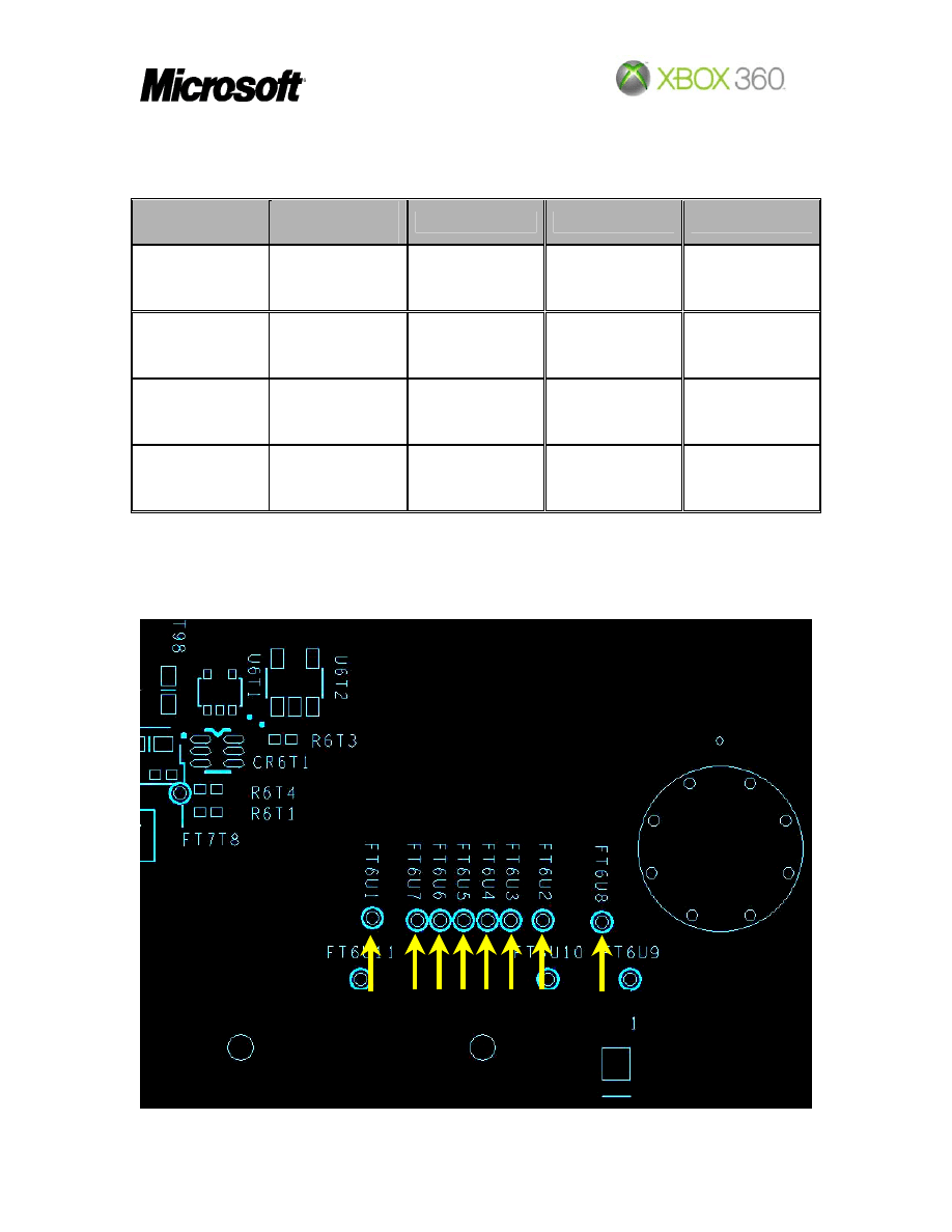
7.9 Category H CPUs Bits
Bits CPU
(Decimal)
Front Panel
Error Code
1st Repair
2nd Repair
3rd Repair
01000000
(64)
0x10, 0x11,
0x12, 0x13,
0x14, 0x15
U4D1 U5F1/U5U1
U3D1/U3R1
10101111
(175)
0x10, 0x11,
0x12, 0x13,
0x14, 0x15
U4D1 U4F1/U4U1
01110101
(117)
0x10, 0x11,
0x12, 0x13,
0x14, 0x15
U4D1
Any CPU Bits
no mentioned
before
0x10, 0x11,
0x12, 0x13,
0x14, 0x15
U4D1
Bit: 0 1 2 3 4 5 6 7
Página 7 de 8
Rev. 3.2

PCBA Debug Guide
Do measures on the test points behind U7D1 (bottom side)
e.g.
Bits order: 76543210
Value 64: 01000000
Value 175:10101111
Página 8 de 8
Rev. 3.2
Document Outline
- 1. Revision History
- 2. Table of Contents
- 3. Introduction
- 4. Scope
- 5. Audience
- 6. Process
- 7. Category Grouping
Wyszukiwarka
Podobne podstrony:
mb memory ga ma785gt ud3h
Memory
Memory 19 07 (rano)
chirstmas misc memory cards 02
EEPROM Memory
memory pauzy
06 Memory Related Perils and Pitfalls
Memory prorocy
opis memory
Teoria 1.0, Phase-change memory
Christmas memory game
0 car key memory pl www przeklej pl
E46 Car Key Memory
Bmw Car Key Memory dis
Implicit memory versus false memory
Faults list of Kuka
Memory apostołowie
więcej podobnych podstron