
INSTRUMENT PANEL
1993 Mitsubishi Montero
1993 ACCESSORIES & EQUIPMENT
Mitsubishi Instrument Panels
Montero
DESCRIPTION & OPERATION
Instrument cluster includes speedometer, fuel gauge and
temperature gauge. Fuel gauge has a built-in voltage limiter to keep
voltage supply to gauges at 7 volts. Some models may also have a
shunt-type ammeter, oil pressure gauge, tachometer, voltmeter and/or
turbo boost pressure gauge. Oil pressure gauge uses full battery
voltage. The tachometer operates by pulse feed.
TROUBLE SHOOTING
FUEL/TEMPERATURE GAUGE NOT WORKING
Check for blown fuse, faulty voltage limiter and faulty
relay. Ensure sending unit connections are clean and tight. Test
sending unit for correct operation. Tighten connections in instrument
cluster.
SPEEDOMETER NOT WORKING
Ensure speedometer cable is properly connected and correctly
routed. If speedometer pointer and/or odometer still do not work,
replace speedometer as an assembly.
TACHOMETER NOT WORKING
Tachometer is serviced as an assembly. If wiring harness is
okay, replace tachometer assembly.
WARNING LIGHTS NOT WORKING
Test for defective sending unit, burned-out bulb and broken
printed circuit. Ensure all connections are clean and tight.
TESTING
FUEL TANK SENDING UNIT
Resistance Test
Remove fuel tank sending unit from fuel tank. Measure
resistance between appropriate terminals with fuel float in FULL and
EMPTY positions. See Fig. 1. Compare resistance reading to FUEL TANK
SENDING UNIT RESISTANCE SPECIFICATIONS table. If resistance is not to
specification, replace fuel tank sending unit.
FUEL TANK SENDING UNIT RESISTANCE SPECIFICATIONS TABLE
Application Specification
Empty ........................................ 103.0-117.0
Full ............................................. 1.0-5.0
FUEL GAUGE
CAUTION: Gauge coils can be damaged if wire is grounded too long.
Perform test as quickly as possible.
Simple Test
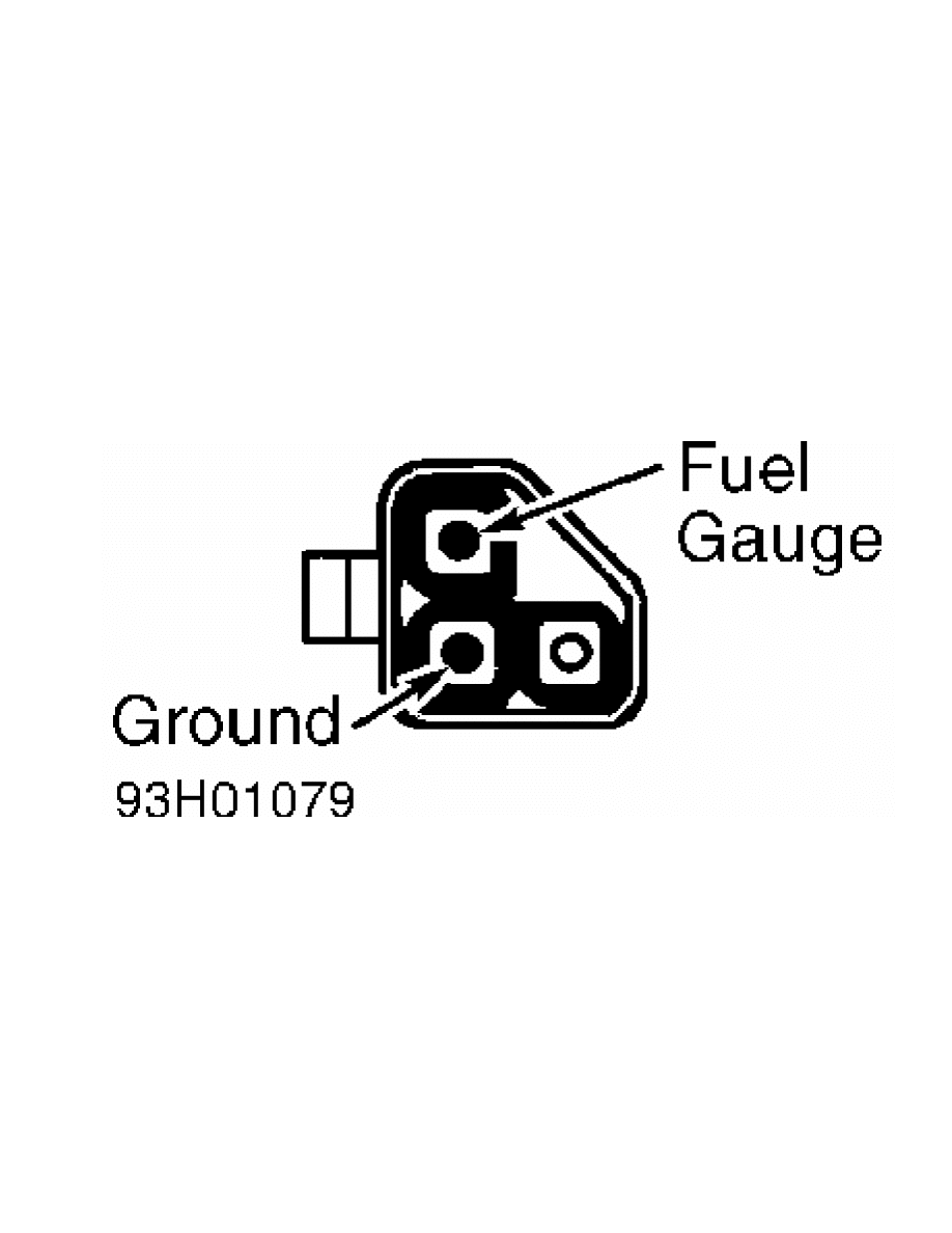
1) Disconnect fuel gauge sending unit connector wire in
luggage compartment, in cargo space or at tank unit. Connect a 12-
volt, 3.4-watt bulb to harness side of connector, between appropriate
terminals. See Fig. 1.
2) Turn ignition switch to ON position. Ensure test bulb
flashes, or stays on, and fuel gauge needle moves. If bulb or gauge
needle does not function as described, check and repair fuel gauge
circuit.
Fig. 1: Fuel Gauge Test Connection ID
Courtesy of Mitsubishi Motor Sales of America.
NOTE: Fuel gauge resistance test must be completed with instrument
panel cluster removed. Use ohmmeter for all measurements. If
resistance is extremely low, a short may exist in coil. If
resistance is extremely high, a broken wire or similar
problem may exist in gauge.
Resistance Test
1) Remove instrument cluster. See INSTRUMENT CLUSTER under
REMOVAL & INSTALLATION.
2) Measure resistance between appropriate terminals of
instrument cluster. See Fig. 2. See FUEL GAUGE RESISTANCE
SPECIFICATIONS table. If resistance readings are not to specification,
replace fuel gauge.
FUEL GAUGE RESISTANCE SPECIFICATIONS TABLE
Terminals Ohms
No. 2 & 3 .................................... 209.7-256.3
No. 1 & 2 ...................................... 77.4-94.6
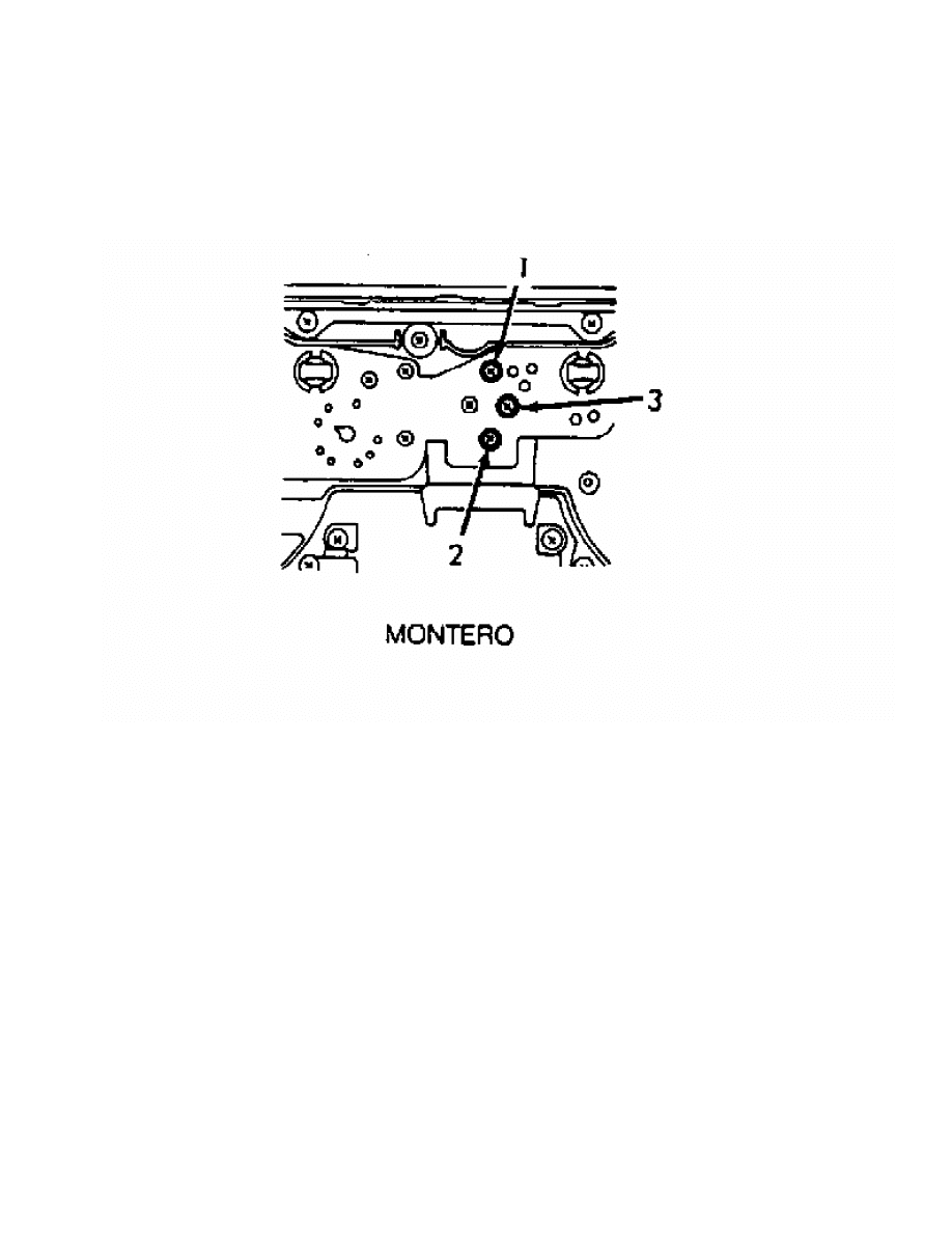
No. 1 & 3 .................................... 132.3-161.7
Fig. 2: Instrument Panel Fuel Gauge Resistance Check Terminal ID
Courtesy of Mitsubishi Motor Sales of America.
OIL PRESSURE GAUGE
Circuit Test
1) Disconnect oil pressure gauge wiring connector from
sending unit inside engine compartment. Connect a 12-volt test light
between harness connector terminal and ground. Turn ignition on, but
DO NOT start engine.
2) If test light comes on and gauge needle moves, go to GAUGE
RESISTANCE TEST. If test light does not come on and gauge needle does
not move, repair wiring to sending unit.
Gauge Resistance Test
1) Remove instrument cluster from instrument panel. See
INSTRUMENT CLUSTER under REMOVAL & INSTALLATION.
2) Check continuity between oil pressure gauge terminals. See
Fig. 3. See OIL PRESSURE GAUGE RESISTANCE SPECIFICATIONS table. If
resistance is not within specification, replace oil pressure gauge.
OIL PRESSURE GAUGE RESISTANCE SPECIFICATIONS TABLE
Application Ohms
Montero ............................................... 50
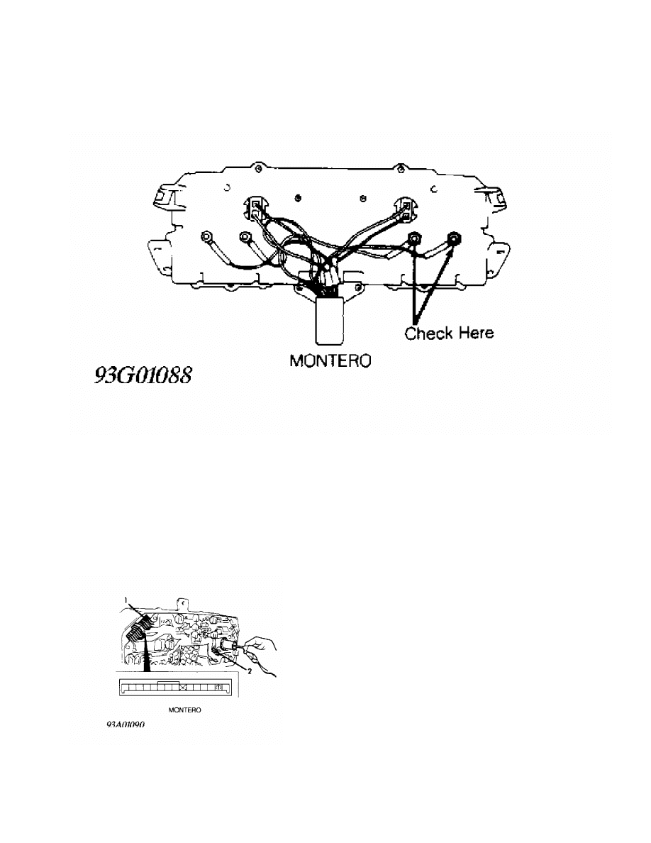
Fig. 3: Oil Pressure Gauge Resistance Test Terminal ID
Courtesy of Mitsubishi Motor Sales of America.
REED SWITCH
Continuity Check
1) Remove instrument cluster. See INSTRUMENT CLUSTER under
REMOVAL & INSTALLATION. Check continuity between reed switch terminals
no. 1 and 2. See Fig. 4.
2) Ensure continuity pulses on and off 4 times per revolution
of speedometer shaft connection. If continuity is not as specified,
replace reed switch.
Fig. 4: Reed Switch Test Terminal ID
Courtesy of Mitsubishi Motor Sales of America.
SPEEDOMETER

Calibration Test
Adjust tire pressure to standard value. Using a calibrated,
reliable speedometer tester, compare reading of vehicle speedometer to
speedometer tester. See SPEEDOMETER ALLOWABLE VARIATION table. Replace
speedometer if necessary.
SPEEDOMETER ALLOWABLE VARIATION TABLE
MPH (km/h) Allowable Variation MPH (km/h)
20 (32) .................................... 19-22 (31-35)
40 (64) .................................... 38-44 (61-71)
60 (97) ................................... 57-66 (92-106)
80 (129) ................................. 76-88 (122-142)
100 (161) ............................... 94-110 (151-177)
TACHOMETER
NOTE: DO NOT reverse polarity when installing tachometer; diode
and transistor may be damaged.
Calibration Test
Connect a calibrated, reliable tach-dwell meter to vehicle
ignition system. Operate engine at various speeds (RPM). See
TACHOMETER ALLOWABLE VARIATION table. If comparison between tach-dwell
meter and vehicle tachometer readings are not within permissible
variation, replace vehicle tachometer.
TACHOMETER ALLOWABLE VARIATION TABLE
Engine Speed (RPM) Allowable Variation (RPM)
1000 ............................................ 900-1100
3000 ........................................... 2850-3150
5000 ........................................... 4750-5250
6000 ........................................... 5700-6300
TEMPERATURE GAUGE
CAUTION: DO NOT connect sender wire directly to ground during test.
Circuit Test
1) Disconnect temperature sender wire from sending unit.
Connect a 12-volt, 3.4-watt test light between connector terminal and
ground. Turn ignition switch to ON position.
2) If test light flashes and temperature gauge needle moves,
go to SENSOR RESISTANCE TEST. If test light does not flash or gauge
needle does not move, repair wiring to sending unit.
Sensor Resistance Test
1) Remove Coolant Temperature Sensor (CTS) from engine.
Sensor is located on intake manifold. Place sending unit in 158
F
(70
C) water. Check sensor resistance using ohmmeter.
2) CTS resistance should be 90-117 ohms. If CTS resistance is
okay, go to GAUGE RESISTANCE TEST. Replace CTS if resistance is not as
specified.
Gauge Resistance Test
1) Remove instrument cluster from instrument panel. See
INSTRUMENT CLUSTER under REMOVAL & INSTALLATION.
2) Measure resistance between temperature gauge terminals at
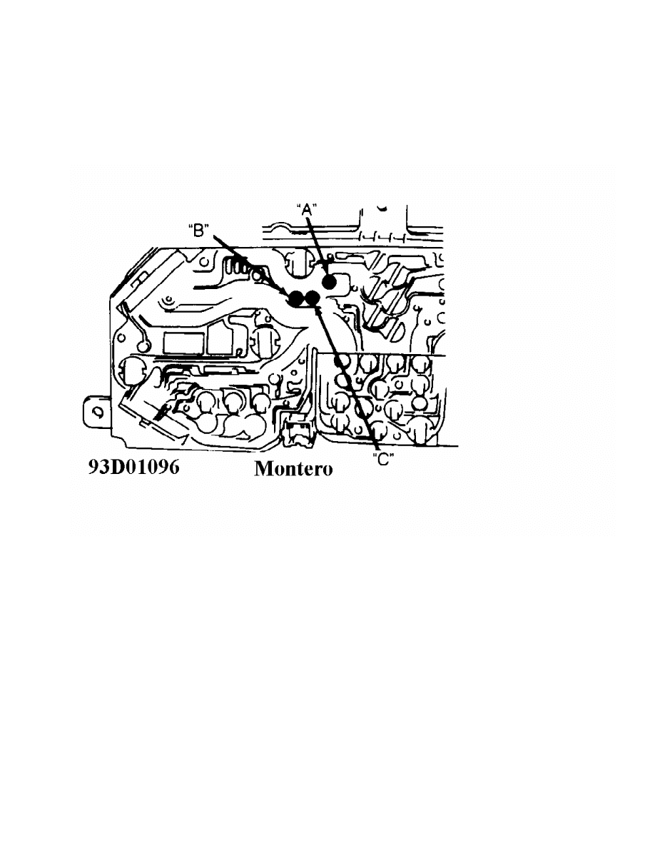
rear of cluster. See TEMPERATURE GAUGE RESISTANCE SPECIFICATIONS
table. See Fig. 5.
Fig. 5: Temperature Gauge Resistance Test Terminal ID
Courtesy of Mitsubishi Motor Sales of America.
TEMPERATURE GAUGE RESISTANCE SPECIFICATIONS TABLE
Terminals Ohms
"A" & "B" ...................................... 67.5-82.5
"A" & "C" .................................... 132.3-161.7
"B" & "C" .................................... 199.8-244.2
VOLTMETER
Resistance Test
Using an ohmmeter, measure resistance between voltmeter
terminals. See Fig. 6. Resistance should be 380-460 ohms.
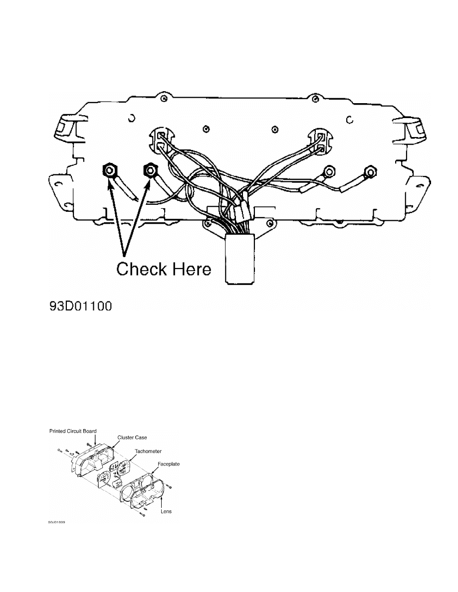
Fig. 6: Voltmeter Resistance Test Terminal ID
Courtesy of Mitsubishi Motor Sales of America.
REMOVAL & INSTALLATION
INSTRUMENT CLUSTER
Removal & Installation
1) Disconnect negative battery cable. Remove instrument
cluster cover plug. Remove cluster cover. Remove screws from
instrument cluster.
2) Disconnect speedometer cable from back of instrument
cluster. Disconnect all connectors attaching cluster. Remove cluster.
To install, reverse removal procedure. See Fig. 7.
Fig. 7: Instrument Cluster Components
Courtesy of Mitsubishi Motor Sales of America.
SPEEDOMETER CABLE

NOTE: When routing speedometer cable, DO NOT bend cable sharply.
Minimum bending radius is 6" (150 mm). Speedometer cable
length varies with transmission type.
Removal
Disconnect speedometer cable from transmission or transaxle.
Remove instrument cluster from instrument panel. See INSTRUMENT
CLUSTER. Disconnect speedometer cable from instrument cluster and/or
adapter (if equipped). Remove speedometer cable from firewall grommet.
Installation
1) Install new cable. Insert cable until stopper seats
properly in groove on rear of speedometer housing. Pull speedometer
cable through firewall grommet until cable marking is visible from
engine compartment.
NOTE: An improperly installed cable can cause fluctuating meter,
noise or damaged harness inside instrument panel.
2) Install adapter onto speedometer cable (if equipped).
Install instrument cluster. See INSTRUMENT CLUSTER. Install cable onto
transmission or transaxle. Check for proper operation.
WIRING DIAGRAMS
See appropriate chassis wiring diagram in the WIRING DIAGRAMS
section.
Wyszukiwarka
Podobne podstrony:
INSTRUMENT PANEL
71 Instrument Panel
71 Instrument Panel and Meter
71 Instrument Panel Meter
INSTRUMENT PANEL
Instrument Panel and Console Trim
71 Instrument Panel
Instrument Panel Wiring Harness
71 Instrument Panel and Meter
71 Instrument Panel Meter
96ZJ 8E INSTRUMENT PANEL SYSTEMS
lab 4 panel operatorski instrukcja
instrukcja do Panel Mio moov 200
NXW102 3 Panel dotykowy LCD instrukcja (2)
lab 4 panel operatorski instrukcja
instrukcja do Panel Mio moov 200
Instrukcja Obsługi Panel pompa Ciepła
Jak cyciagnac panel MMI w Audi A8 D3 instrukcja
więcej podobnych podstron