2009 Chevrolet Aveo
|
Aveo, Wave, G3, Barina (VIN S/T) Service Manual
|
Body Hardware and Trim
|
Instrument Panel and Console Trim
|
Repair Instructions
| Document ID: 2147544
Instrument Panel Lower Center Trim Replacement
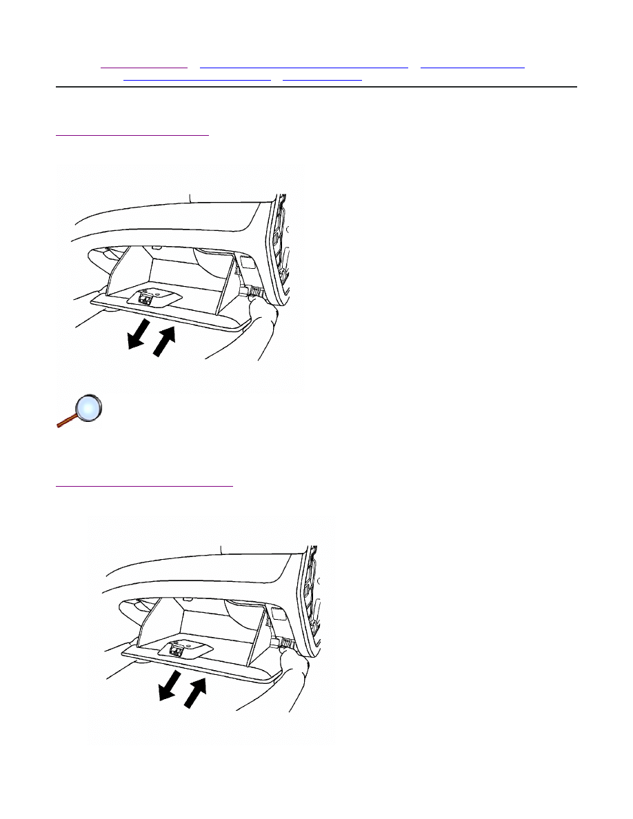
Removal Procedure
Remove the instrument panel lower center trim panel (1) using a taped flat-bladed tool.
Installation Procedure
© 2010 General Motors Corporation. All rights reserved.
Page 1 of 2
Document ID: 2147544
7/5/2010
http://localhost:9001/si/showDoc.do?docSyskey=2147544&pubCellSyskey=148114&pubO...

Install the instrument panel lower center trim panel (1).
Page 2 of 2
Document ID: 2147544
7/5/2010
http://localhost:9001/si/showDoc.do?docSyskey=2147544&pubCellSyskey=148114&pubO...
2009 Chevrolet Aveo
|
Aveo, Wave, G3, Barina (VIN S/T) Service Manual
|
Body Hardware and Trim
|
Instrument Panel and Console Trim
|
Repair Instructions
| Document ID: 2095947
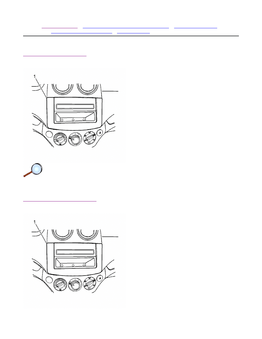
Instrument Panel Center Trim Panel Replacement
Removal Procedure
1. Remove the instrument panel lower trim panel. Refer to
Instrument Panel Lower Trim Panel
Replacement
.
2. Using a taped flat-bladed tool, remove the instrument panel center trim panel (1).
Installation Procedure
© 2010 General Motors Corporation. All rights reserved.
Page 1 of 2
Document ID: 2095947
7/5/2010
http://localhost:9001/si/showDoc.do?docSyskey=2095947&pubCellSyskey=157421&pubO...

1. Install the instrument panel center trim panel (1).
2. Install the instrument panel lower trim panel. Refer to
Instrument Panel Lower Trim Panel
Replacement
.
Page 2 of 2
Document ID: 2095947
7/5/2010
http://localhost:9001/si/showDoc.do?docSyskey=2095947&pubCellSyskey=157421&pubO...
2009 Chevrolet Aveo
|
Aveo, Wave, G3, Barina (VIN S/T) Service Manual
|
Body Hardware and Trim
|
Instrument Panel and Console Trim
|
Repair Instructions
| Document ID: 2147540
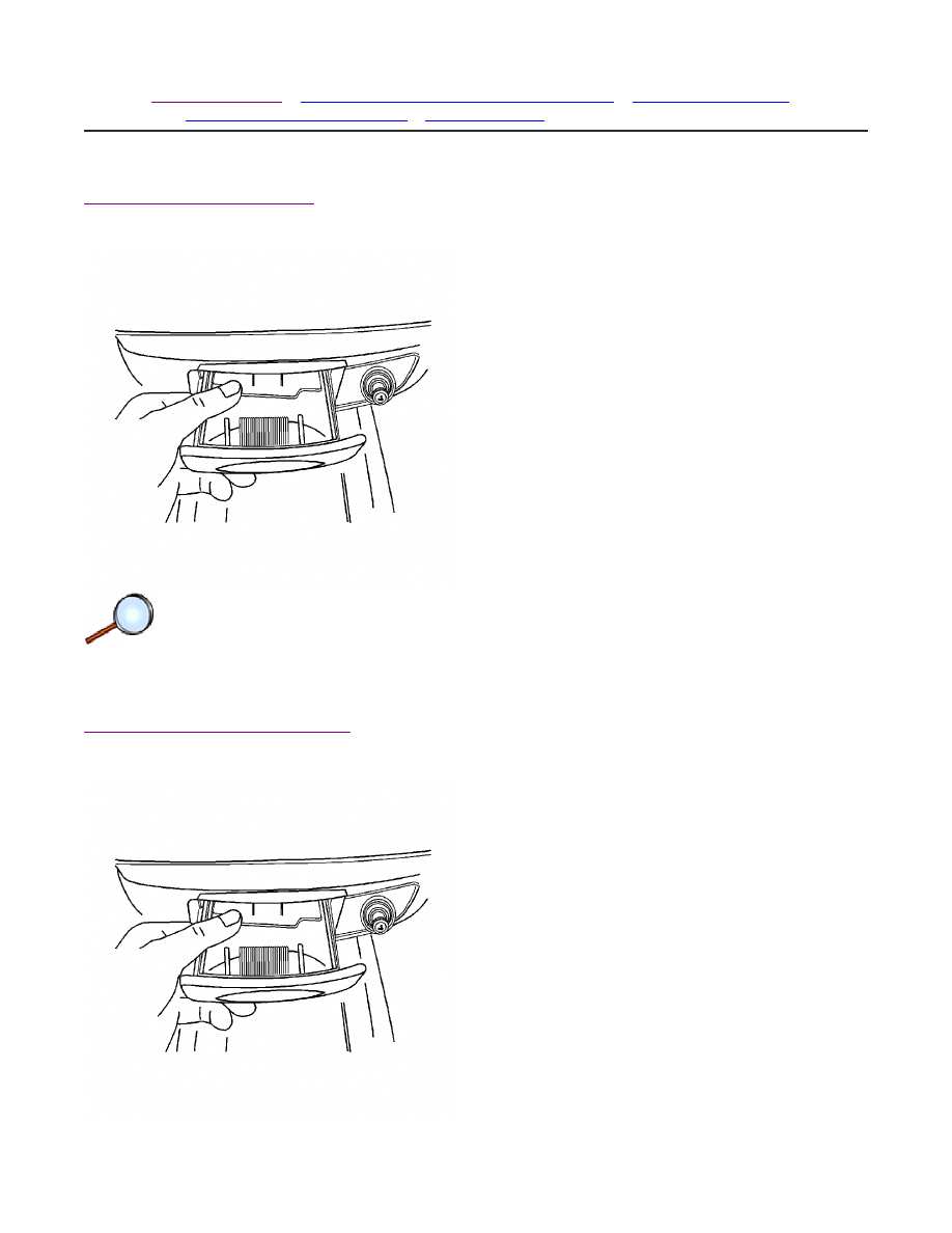
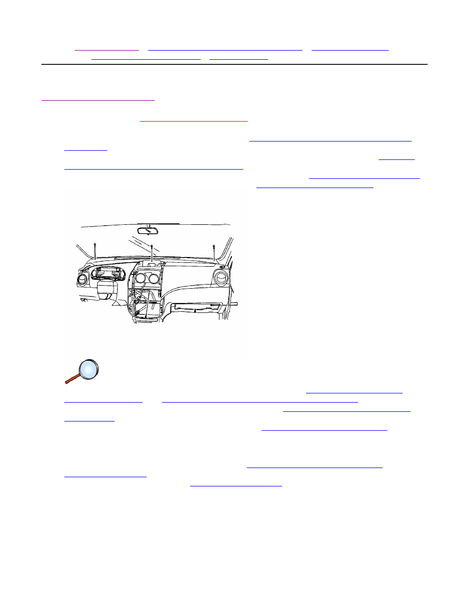
Instrument Panel Lower Trim Panel Replacement
Removal Procedure
Remove the instrument panel lower trim panel (1) using a taped flat-bladed tool.
Installation Procedure
© 2010 General Motors Corporation. All rights reserved.
Page 1 of 2
Document ID: 2147540
7/5/2010
http://localhost:9001/si/showDoc.do?docSyskey=2147540&pubCellSyskey=157426&pubO...

Install the instrument panel lower trim panel (1).
Page 2 of 2
Document ID: 2147540
7/5/2010
http://localhost:9001/si/showDoc.do?docSyskey=2147540&pubCellSyskey=157426&pubO...
2009 Chevrolet Aveo
|
Aveo, Wave, G3, Barina (VIN S/T) Service Manual
|
Body Hardware and Trim
|
Instrument Panel and Console Trim
|
Repair Instructions
| Document ID: 1285211
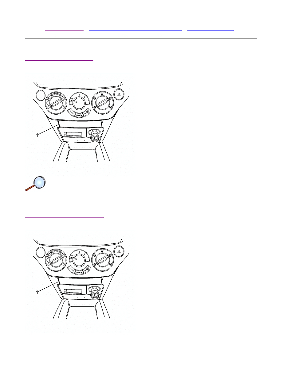
Ashtray Replacement
Removal Procedure
Remove the ashtray.
Installation Procedure
© 2010 General Motors Corporation. All rights reserved.
Page 1 of 2
Document ID: 1285211
7/5/2010
http://localhost:9001/si/showDoc.do?docSyskey=1285211&pubCellSyskey=148171&pubO...

Install the ashtray.
Page 2 of 2
Document ID: 1285211
7/5/2010
http://localhost:9001/si/showDoc.do?docSyskey=1285211&pubCellSyskey=148171&pubO...
2009 Chevrolet Aveo
|
Aveo, Wave, G3, Barina (VIN S/T) Service Manual
|
Body Hardware and Trim
|
Instrument Panel and Console Trim
|
Repair Instructions
| Document ID: 1724478
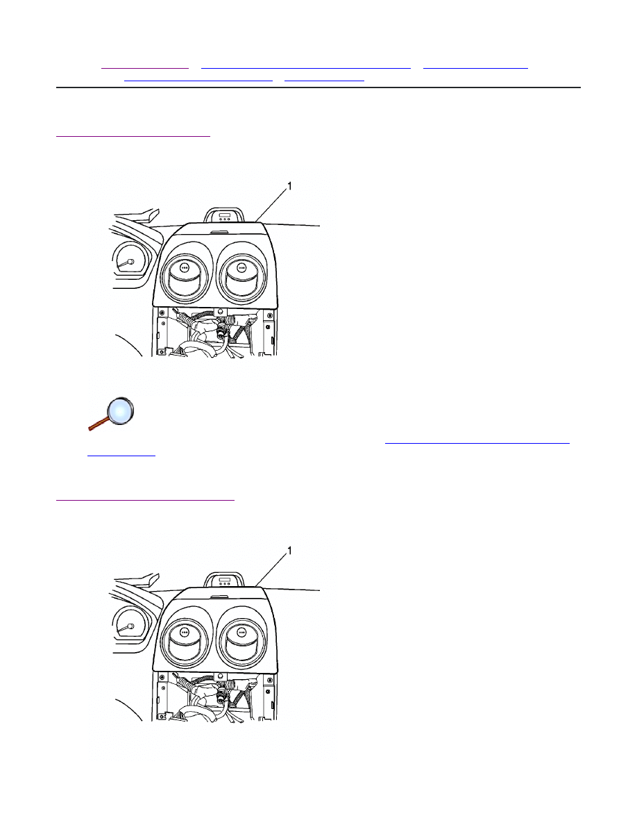
Instrument Panel Storage Compartment Replacement
Removal Procedure
Open and remove the glove box.
Installation Procedure
© 2010 General Motors Corporation. All rights reserved.
Page 1 of 2
Document ID: 1724478
7/5/2010
http://localhost:9001/si/showDoc.do?docSyskey=1724478&pubCellSyskey=148141&pubO...

1. Position the glove box in the instrument panel.
2. Install the glove box.
Page 2 of 2
Document ID: 1724478
7/5/2010
http://localhost:9001/si/showDoc.do?docSyskey=1724478&pubCellSyskey=148141&pubO...
2009 Chevrolet Aveo
|
Aveo, Wave, G3, Barina (VIN S/T) Service Manual
|
Body Hardware and Trim
|
Instrument Panel and Console Trim
|
Repair Instructions
| Document ID: 2095951
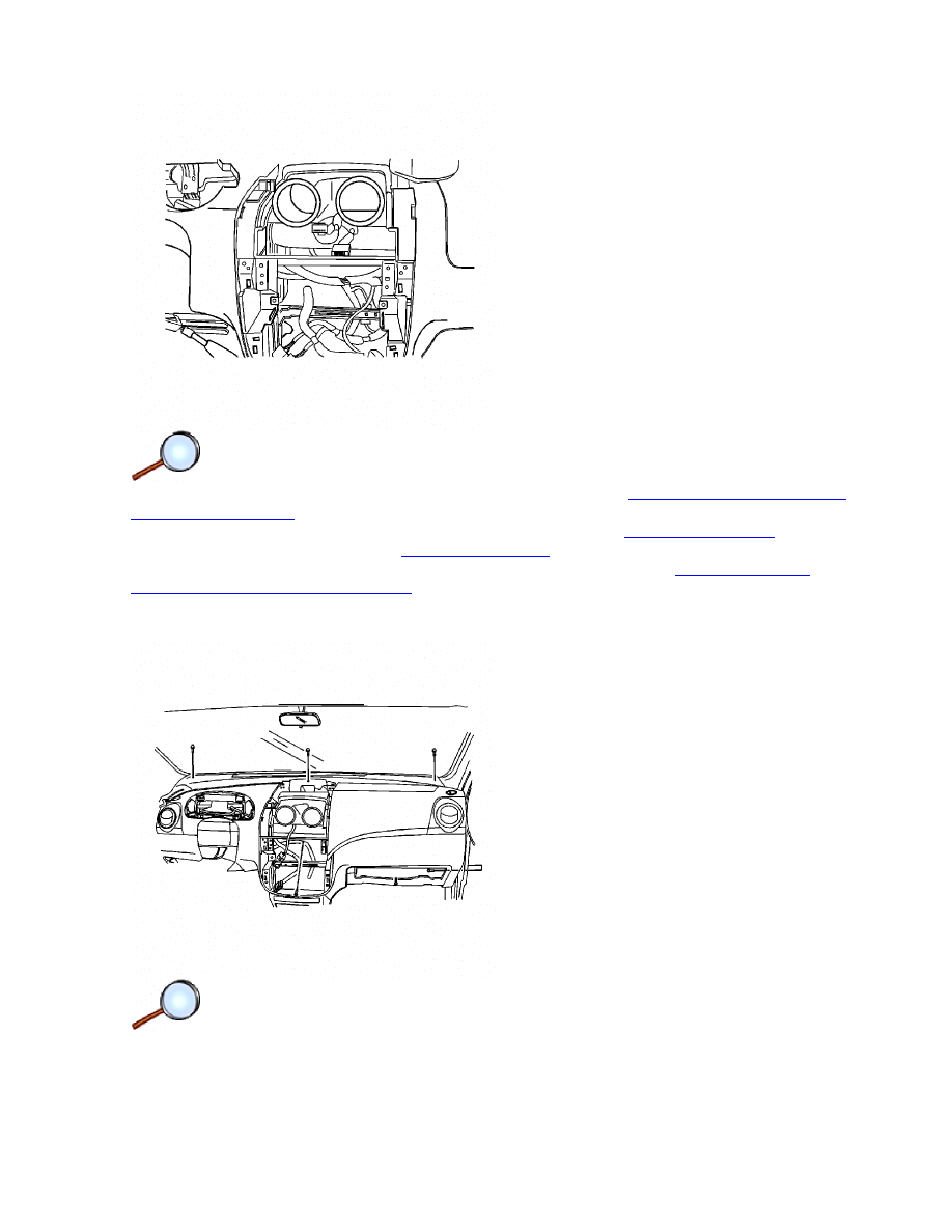
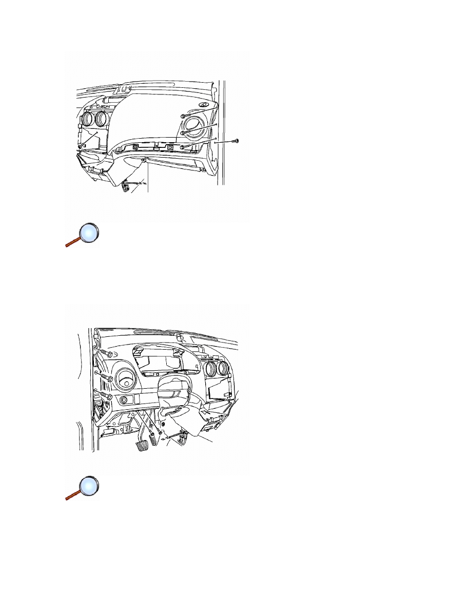
Instrument Panel Assembly Replacement (Notchback)
Removal Procedure
Warning:
Refer to
Battery Disconnect Warning
in the Preface section.
1. Disconnect the negative battery cable. Refer to
Battery Negative Cable Disconnection and
Connection
.
2. Remove the driver air bag module from the steering wheel, if equipped. Refer to
Inflatable
Restraint Steering Wheel Module Replacement
.
3. Remove the steering wheel from the steering column. Refer to
Steering Wheel Replacement
.
4. Remove the steering column trim cover. Refer to
Steering Column Replacement
.
5. Remove the signal lamp switch and the wiper switch. Refer to
Turn Signal Multifunction
Switch Replacement
and
Windshield Wiper and Washer Switch Replacement
.
6. Remove the windshield pillar garnish moldings. Refer to
Windshield Pillar Garnish Molding
Replacement
.
7. Remove the instrument cluster assembly. Refer to
Instrument Cluster Replacement
.
8. Remove the side cover.
9. Using a taped flat-bladed tool, gently pry and remove the instrument panel lower cover.
10. Remove the instrument panel center vent panel.
11. Remove the cigar lighter and ashtray. Refer to
Cigar Lighter Housing Replacement
and
Ashtray Replacement
.
12. Remove the cupholder. Refer to
Cupholder Replacement
.
© 2010 General Motors Corporation. All rights reserved.
Page 1 of 6
Document ID: 2095951
7/5/2010
http://localhost:9001/si/showDoc.do?docSyskey=2095951&pubCellSyskey=148174&pubO...
13. Remove the A/C controller from the instrument panel. Refer to
Heater and Air Conditioning
Control Replacement
.
14. Remove the audio system from the instrument panel. Refer to
Radio Replacement
.
15. Remove the digital clock. Refer to
Clock Replacement
.
16. Remove the glove box assembly from the instrument panel. Refer to
Instrument Panel
Storage Compartment Replacement
.
17. Remove the screws from the ALDL connector.
18. Disconnect the necessary electrical connectors.
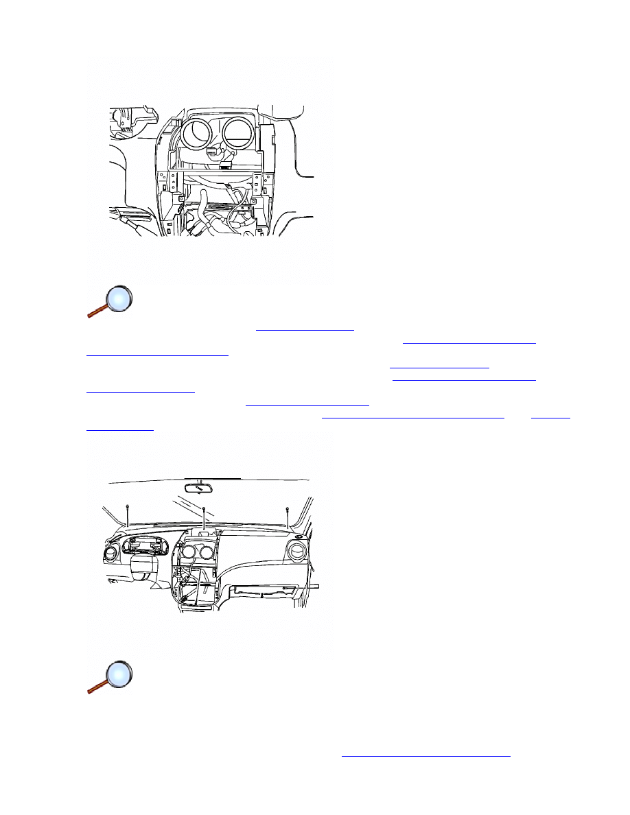
19. Remove the three bolts from the upper instrument panel.
Page 2 of 6
Document ID: 2095951
7/5/2010
http://localhost:9001/si/showDoc.do?docSyskey=2095951&pubCellSyskey=148174&pubO...
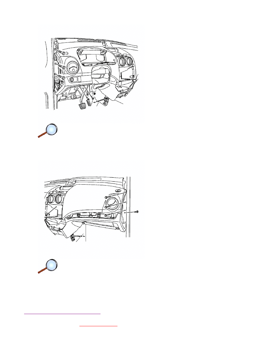
20. Remove the instrument panel screw behind the HVAC controls.
21. Remove the instrument panel bolts above the steering column.
22. Remove the instrument panel bolts from the ends of the instrument panel.
23. Remove the two nuts from the lower left center of the instrument panel.
24. Remove the instrument panel end screws.
25. Remove the two nuts from the lower right center of the instrument panel.
26. Remove the tie-bar retaining bolts.
27. Disconnect the wire harness from the instrument panel.
28. Remove the instrument panel from the vehicle.
Installation Procedure
Caution:
Refer to
Fastener Caution
in the Preface section.
Page 3 of 6
Document ID: 2095951
7/5/2010
http://localhost:9001/si/showDoc.do?docSyskey=2095951&pubCellSyskey=148174&pubO...
1. Install the instrument panel assembly with the right side end screws and tighten to 20 N·m
(15 lb ft).
2. Install the tie bar retaining bolts and tighten to 20 N·m (15 lb ft).
3. Connect the wire harness to the instrument panel.
4. Install the two nuts to the lower right center of the instrument panel.
5. Connect the ALDL connector with the screws.
6. Install the instrument panel bolts to the left side of the instrument panel and tighten to
20 N·m (15 lb ft).
7. Install the two nuts to the lower left center of the instrument panel.
8. Install the instrument panel bolts above the steering column and tighten to 20 N·m
(15 lb ft).
9. Install the instrument panel screw behind the HVAC assembly and tighten to 4 N·m
(35 lb in).
Page 4 of 6
Document ID: 2095951
7/5/2010
http://localhost:9001/si/showDoc.do?docSyskey=2095951&pubCellSyskey=148174&pubO...
10. Install the digital clock. Refer to
Clock Replacement
.
11. Install glove box assembly to the instrument panel. Refer to
Instrument Panel Storage
Compartment Replacement
.
12. Install the audio system to the instrument panel. Refer to
Radio Replacement
.
13. Install the A/C controller to the instrument panel. Refer to
Heater and Air Conditioning
Control Replacement
.
14. Install the cupholder. Refer to
Cupholder Replacement
.
15. Install the cigar lighter and ashtray. Refer to
Cigar Lighter Housing Replacement
and
Ashtray
Replacement
.
16. Install the instrument panel center vent panel.
17. Install the instrument panel lower cover.
18. Connect the necessary electrical connectors.
19. Install the side cover.
20. Install the instrument cluster assembly. Refer to
Instrument Cluster Replacement
.
Page 5 of 6
Document ID: 2095951
7/5/2010
http://localhost:9001/si/showDoc.do?docSyskey=2095951&pubCellSyskey=148174&pubO...

21. Install the windshield pillar garnish molding. Refer to
Windshield Pillar Garnish Molding
Replacement
.
22. Install the signal lamp switch and the wiper switch. Refer to
Turn Signal Multifunction Switch
Replacement
for signal, and refer to
Windshield Wiper and Washer Switch Replacement
.
23. Install the steering column trim cover. Refer to
Steering Column Replacement
.
24. Install the steering wheel to the steering column. Refer to
Steering Wheel Replacement
.
25. Install the driver air bag module to the steering wheel, if equipped. Refer to
Inflatable
Restraint Steering Wheel Module Replacement
.
26. Connect the negative battery cable. Refer to
Battery Negative Cable Disconnection and
Connection
.
Page 6 of 6
Document ID: 2095951
7/5/2010
http://localhost:9001/si/showDoc.do?docSyskey=2095951&pubCellSyskey=148174&pubO...
2009 Chevrolet Aveo
|
Aveo, Wave, G3, Barina (VIN S/T) Service Manual
|
Body Hardware and Trim
|
Instrument Panel and Console Trim
|
Repair Instructions
| Document ID: 2096014
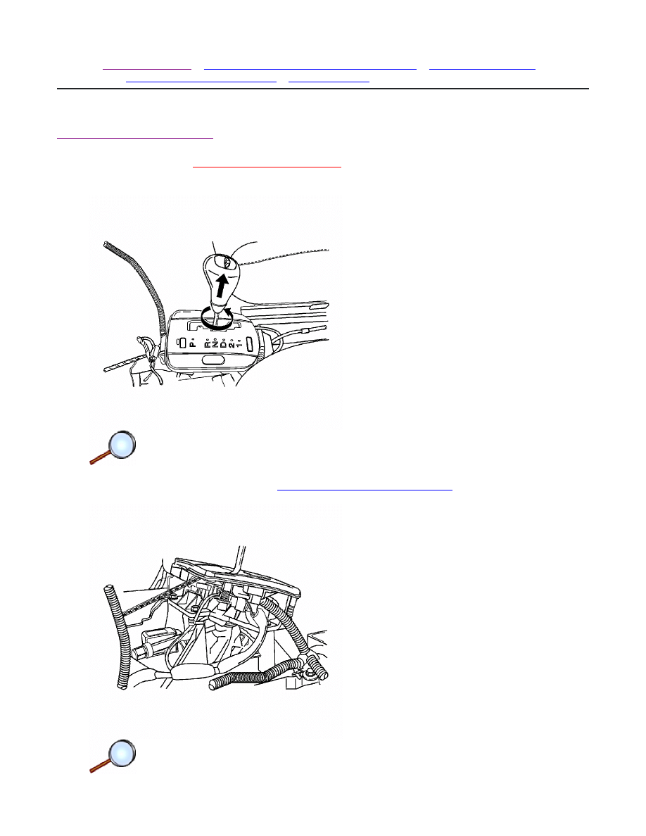
Console Shift Lever Bezel Replacement
Removal Procedure
Warning:
Refer to
Battery Disconnect Warning
in the Preface section.
1. Disconnect the negative battery cable.
2. Remove the floor console. Refer to
Front Floor Console Replacement
.
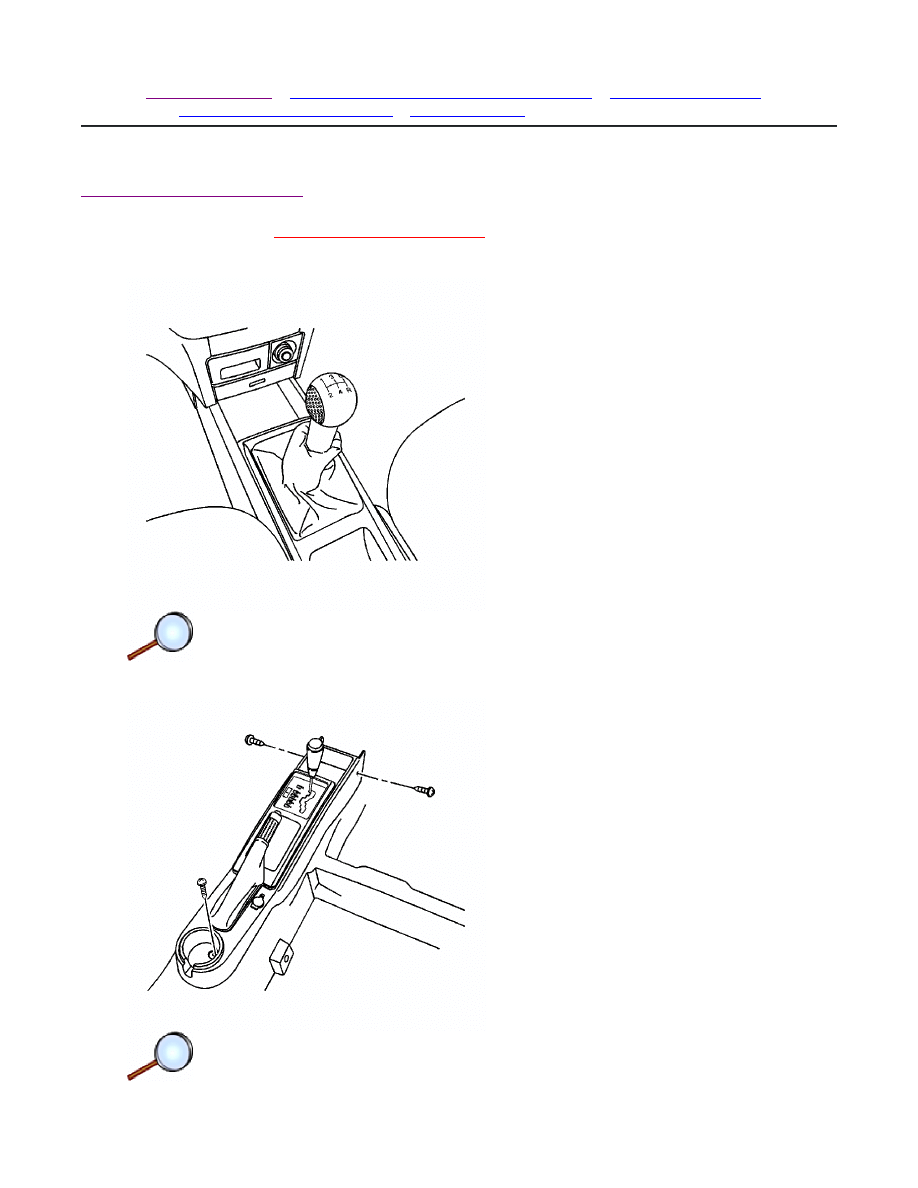
3. Remove the shift select lever knob.
© 2010 General Motors Corporation. All rights reserved.
Page 1 of 2
Document ID: 2096014
7/5/2010
http://localhost:9001/si/showDoc.do?docSyskey=2096014&pubCellSyskey=148201&pubO...
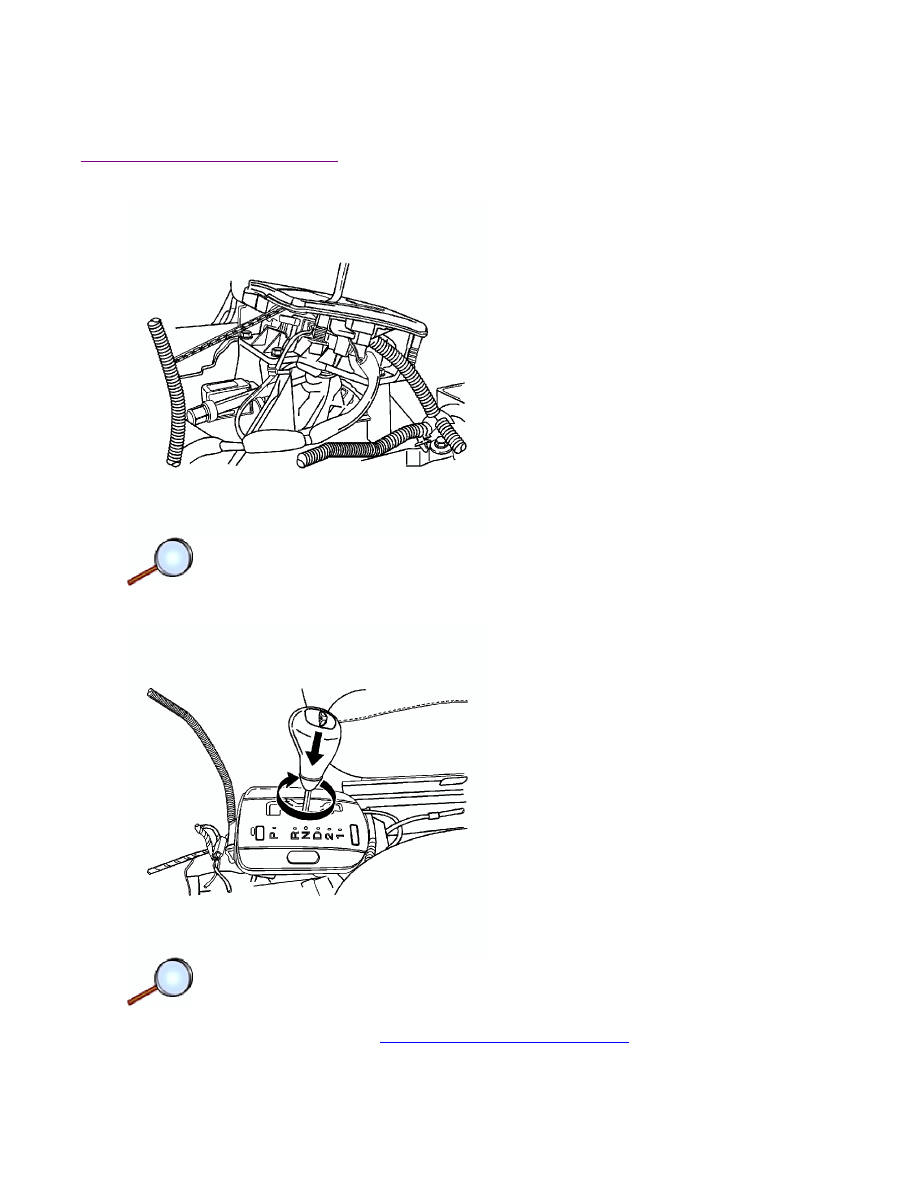
4. Disconnect the connectors.
5. Remove the shift select cover from the shift select housing.
Installation Procedure
1. Connect the connectors to the shift select cover.
2. Install the shift select cover to the hole.
3. Install the shift select lever knob.
4. Install the floor console. Refer to
Front Floor Console Replacement
.
5. Connect the negative battery cable.
Page 2 of 2
Document ID: 2096014
7/5/2010
http://localhost:9001/si/showDoc.do?docSyskey=2096014&pubCellSyskey=148201&pubO...
2009 Chevrolet Aveo
|
Aveo, Wave, G3, Barina (VIN S/T) Service Manual
|
Body Hardware and Trim
|
Instrument Panel and Console Trim
|
Repair Instructions
| Document ID: 2096037
Front Floor Console Replacement (Notchback)
Removal Procedure
Warning:
Refer to
Battery Disconnect Warning
in the Preface section.
1. Disconnect the negative battery cable.
2. Remove the gearshift lever boot, if equipped.
3. Remove the screws from the floor console.
© 2010 General Motors Corporation. All rights reserved.
Page 1 of 3
Document ID: 2096037
7/5/2010
http://localhost:9001/si/showDoc.do?docSyskey=2096037&pubCellSyskey=148209&pubO...
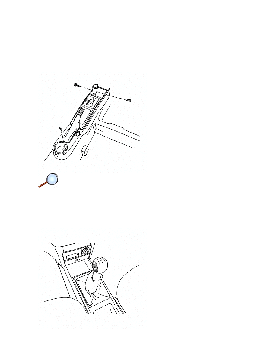
4. Remove the floor console cover.
5. Remove the parking brake cover.
6. Disconnect the electrical connector.
7. Remove the floor console.
Installation Procedure
1. Connect the electrical connector.
Caution:
Refer to
Fastener Caution
in the Preface section.
2. Install the floor console with the screws and tighten to 4 N·m (35 lb in).
3. Install the parking brake cover.
4. Install the floor console cover.
Page 2 of 3
Document ID: 2096037
7/5/2010
http://localhost:9001/si/showDoc.do?docSyskey=2096037&pubCellSyskey=148209&pubO...

5. Install the gearshift lever boot, if equipped.
6. Connect the negative battery cable.
Page 3 of 3
Document ID: 2096037
7/5/2010
http://localhost:9001/si/showDoc.do?docSyskey=2096037&pubCellSyskey=148209&pubO...
Document Outline
Wyszukiwarka
Podobne podstrony:
71 Instrument Panel and Meter
71 Instrument Panel and Meter
EXTERIOR AND INTERIOR TRIM
INSTRUMENT PANEL
71 Instrument Panel
76 Exterior and Interior Trim
76 Exterior and Interior Trim
71 Instrument Panel Meter
EXTERIOR AND INTERIOR TRIM
INSTRUMENT PANEL
71 Instrument Panel
instrument panel
Instrument Panel Wiring Harness
71 Instrument Panel Meter
96ZJ 8E INSTRUMENT PANEL SYSTEMS
lab 4 panel operatorski instrukcja
więcej podobnych podstron