®
MAGNETIC CONTACTS
with 2EOL resistor
K-1 2E, K-2 2E, K-3 2E
k123-2e_e 10/06
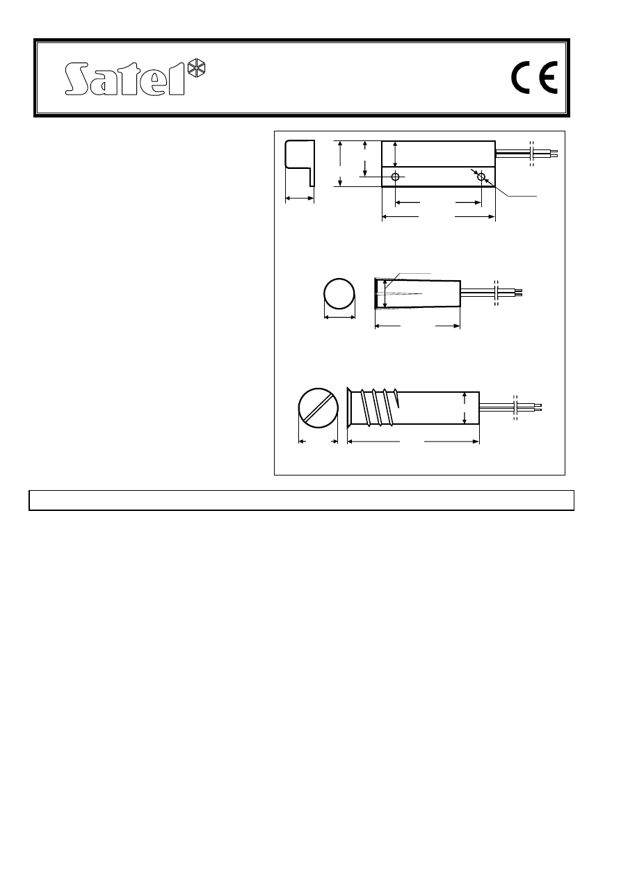
The magnetic contacts consist of two
elements: magnetic sensor (reed switch) and
magnet. The reed switch, which is situated
near the magnet, makes the electric circuit.
Each of the magnetic contact elements is
placed in an identical watertight housing, the
part with reed switch having electric lead-
outs (Fig. 1,2,3). Inside the housing together
with the reed switch are installed two 1.1k
Ω
resistors connected with the reed switch in
2EOL configuration (see Fig. 5). They enable
the control panel to detect a tamper of the
magnetic contact by monitoring the
resistance changes on the zone. Each
detector of this type must be connected to a
separate zone of the control panel.
Individual magnetic contacts differ in the
housing style and the way of mounting. The
K-1 2E is designed for surface mounting and
the K-2 E & K-3 2E for flush mounting.
The magnetic contacts can be used
wherever required for controlling the status
of doors, windows and/or other movable
elements, e.g. for protection or monitoring of
access to particular sites, spaces, facilities;
in automatic control systems, etc.
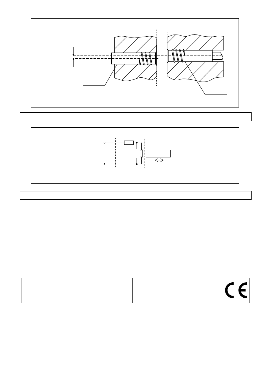
INSTALLATION – Fig. 4
The magnetic contact element containing the magnet should be mounted on the movable part, while the
reed switch - on the stationary part of protected doors, windows, etc. Elements of the K-1 2E magnetic
contact should be attached to the surface by means of screws, suitable glue, or a two-side self-adhesive
tape. The K-2 E & K-3 2E magnetic contacts are designed for face mounting in such materials as wood
or plastic (Fig. 4). The walls, the magnetic contact is to be fitted in, should be at least 10mm thick, so as
to ensure adequate stability for the elements mounted. To make holes for the K-2 2E magnetic contact,
use ø8mm drill, and for the K-3 2E magnetic contact - ø9mm drill. The K-2 2E is to be pressed in, while
the K-3 2E, which has a thread, needs to be screwed in. The mounted magnetic contact elements can
be reinforced with a suitable glue.
In order to ensure correct functioning of the magnetic contact, the distance between magnet and reed
switch should not exceed 12-15mm for K-1 2E & K-2 2E, and 15-18mm for K-3 2E. Misalignment of the
axes of magnet and reed switch in cylindrical magnetic contacts should not be greater than 10mm for
K-2 2E and 12mm for K-3 2E.
Notes:
•
You are in no case allowed to shorten (cut short) the element containing the magnet.
•
Special care must be taken when installing reed contact part of the detector. It should not be
hammered into the slot, because the fragile component inside the detector might be damaged then.
•
When screwing the K-3 2E reed relay in, the wire will get twisted; to prevent it from damage, make
sure that it has a sufficient spare length, or twist it in the opposite direction before installation so that
it can straighten out when mounted.
Fig. 1 K-1 2E reed switch in plastic housing
Fig. 2 K-2 2E reed switch in plastic housing
Fig. 3 K-3 2E reed switch in metal housing
8,8mm
25mm
8mm
11mm
36mm
9mm
7,3mm
25mm
33,5mm
13,5mm
Ø2mm
7,3mm
10,5mm
HOOKUP – Fig. 5
TECHNICAL DATA
Magnetic contact type ............................................................................................................2EOL/NC
Resistance................................................................................................................................
2x1,1kΩ
Maximum switchable voltage of reed switch ..................................................................................200V
Maximum switchable current ......................................................................................................500mA
Maximum continuous (non-switchable) current ..............................................................................1,5 A
Rated power ................................................................................................................................ 10 VA
Minimum number of switchings under load
1V, 10mA ....................................................... 1000x10
6
10V,
10mA ....................................................... 500x10
6
50V,
100mA ......................................................... 2x10
6
100V,
100mA ....................................................... 2x10
6
Contact material............................................................................................................. Ru (ruthenium)
SATEL sp. z o.o.
ul. Schuberta 79
80-
172 Gdańsk
POLAND
tel. +48 58 320 94 00
info@satel.pl
www.satel.pl
Latest EC declaration of conformity
and product approval certificates
can be downloaded from Web site
www.satel.pl
wall thickness
min 10 mm
distance
max 15-18mm
reed switch axis
max
misalignment
12mm
magnet
magnet axis
reed switch
Fig. 4 Example of face mounting of K-3 2E magnetic contact
Zone Z
n
COM
Fig. 5 Connection of the magnetic contact with 2EOL resistor to the control panel.
2EOL resistor
(R=1,1k
Ω
) in the reed
switch housing
reed switch
R
R
MAGNET
Wyszukiwarka
Podobne podstrony:
k123 2e
k123 2e pl(2)
k123 2e
aqua pet 2e io int 0314
Mutants & Masterminds 1e to 2e Conversion Guide
Materiałoznawstwo i Techniki Wytwarzania Sprawozdanie 2E
2e Diety głodowe
KOLOKWIUM 2e Biologi1, chemia organiczna(1)
Matura Solutions NEW Upp-Intermed. 2E SB E-WB PL
Konspekt 2E - Biedni i bogaci współczesnego świata
Exalted Dreams of the First Age Map of Creation 2e
KOLOKWIUM 2e Biologia, chemia organiczna(1)
Earthdawn Character Sheet 2e
k123
2e
więcej podobnych podstron