Fuel from 'Burning Water'
provided by The Reclamation Project
*** Working Plans ***
01/09/02
UltimateMallStore Disclaimer: We have indication these plans work when built,
but every person is unique this depends on your ability to make it work,also we
are not responsible for any accidents or injuries,etc so please be careful ,if you
choose to try it, use common sense and start SMALL, like a lawnmower engine,
please report any successes you might have.
The following file was recieved by Dave the Gravman via FAX, he kindly sent it
to me, thanks Dave!
•
Convert your engine to burn hydrogen & oxygen
•
Make vapor from water on demand & pollution-free
•
Convert your vehicle to a ZPV: Zero Pollution Vehicle
•
Freedom from Gasoline
•
Simple and inexpensive conversion
•
On Demand vapor rate via throttle
•
Easy do it yourself public domain plans
•
Help clean the air while you save money
These plans can be used to run your car, truck, RV, motorcycle, airplane, etc.
from tap water.

Are you fed up with ga$oline price$ and THE POLLUTION?
Would you like to do something about it besides complain and wait?
Are you still CHOKING on the whole idea of fossil fuel CON$UMPTION?
WHY?
Wouldn't you like to free yourself from centrally-controlled or imported fuel?
Do you have a 2nd vehicle you don't use every day?
Now there is something we can actually do about it, as individuals willing to help
clean the environment, and travel at lower cost to both you and your
environment. Do-it-yourself plans allow the individual (that's you and me, folks)
to make a difference.
This is the easiest and lowest cost way to convert your car to run on (relatively)
free energy. Now with existing technology, anyone can stand up and make a
difference by reducing the local automotive pollution, eliminate ga$oline
expen$e$, help restore our atmosphere, and breathe a little easier. You will be
making use of your entire existing system, except the fuel tank and catalytic
converter.
THE PLAN:
Know the Truth and set yourself FREE. Set a good example for the World you
choose to create. Exercise your own Free Will. Live cleaner and healthier.
Build and install a low-cost alternative method for running your vehicle (internal
combustion) engine on TAP WATER, using off-the-shelf components. This is
simply an efficient way to convert ordinary tap water into gaseous Hydrogen and
Oxygen, and then burn these vapours in the engine, instead of that $melly,
$tinky, expen$ive 'other $tuff.
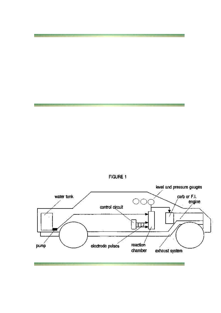
This 'minisystem' runs easily from your existing battery and electrical system,
and it plugs into your carburetor with simple off-the-shelf fittings. You will be
installing a plastic water tank, a control circuit, a reaction chamber, a hi-
pressure carb/FI fitting, and 3 gauges (see Figure 1), and then hooking into your
existing carb/FI.
The SIMPLICITY comes from being an 'on-demand' system requiring no fancy
storage, or plumbing. You crank the gas pedal or throttle and you electrically
create more vapour for immediate consumption, on demand; Lo - Hi Flow Rate
as needed from idle - max power. The only real change is that you are using tap
water as fuel, instead of the traditional petroleum-based fuel. Given, a choice,
which way would you choose?

FAQs
Q: Does it really work?
A: Yes; this is well-established technology dating back to stainless steel. But be
sure to follow these instructions using the proper mechanical and electrical
assembly techniques, as it incorporates the best qualities of several techniques.
Q: How does it qualify as 'free energy'?
A: If you're paying someone for the water you use, then it is not strictly 'free'.
But, the alternative is to keep buying into the expen$ive ga$oline and re$ultant
hydrocarbon pollution.
Q: ls it Safe?
A: Technically, it is safer than running on fossil fuel, because you are no longer
choking on your own emissions (health-wise), but in general it is practically as
safe as your current gasoline arrangement. You will be installing a few simple
safety devices, using current automotive standards.
Q: What kind of performance can I expect?
A: Properly adjusted, your modified vapour-only fuel system will run cooler, and
at a modestly higher power level. The mileage performance expected from this
design ranges from 50-300 mpg, depending on your adjusting skills.
Q: Can I do the modification myself?
A: Why not? If you know someone with basic mechanical and/or electrical skills,
you can even delegate some of the construction. If you are using a fuel-injected
engine, you may have to get a mechanic's opinion.
0: What is the environmental impact that my vehicle will have?
A: It will be producing H20 steam and unburnt 02, hence it will be cleaning the
environment, rather than dumping nauseous toxins into it. Plus you will be
helping to save our dwindling supply of atmospheric oxygen. Any excess vapour
in the reaction becomes either steam or oxygen. You can also expect to be
receiving more than casual interest from those around you.
Q: Is this really a steam engine?
A: No; really. Exceedingly hi temp & pressure are not used. This is strictly an
internal combustion engine (burning orthohydrogen) with residual steam in the
exhaust as a by product.
Gasoline as a fuel is NOT NECESSARY; it is optional.

1. ORIGIN - In the 19th century, the gasoline portion of the refining process, was
first considered to be a 'waste' product of extracting the purified crude oil. Later
on, it was discovered that it could be $old as fuel, instead of just dumping it back
in the hole as had been the tradition.
2. CONSUMPTION RATE - The gasoline consumption rate for every mass-
produced car has been carefully 'designed in' as a market asset. As an indication,
simply observe how quickly and closely ALL the local different gas stations
adjust their prices. Even the hybrid cars which use electric motors still consume
a designed amount of gasoline, and their price tags are prohibitively high.
3. EFFICIENCY - There is a lot of thermochemical energy in gasoline, but there
is even more energy in water. The DOE has quoted about 40%, 50 it is probably
much more than that. Most people are unaware that 'internal combustion' is
DEFINED as: a thermo-vapour process; as in 'no liquid in the reaction'; AND
most of the gasoline in a standard internal combustion engine, is ACTUALLY
CONSUMED cooked and finally broken down) IN THE CATALYTIC
CONVERTER, which happens AFTER the fuel has been not-so-burnt in the
engine. Sadly, this means that most of the fuel we use in this way, is used only to
cool down the combustion process, rather than using a cleaner and more efficient
means to do so.
4. ADDITIVES - Also sadly, we are told by 'authorities' that some of the many
gasoline additives are in the mix to increase performance; but because of its
current overly-complex molecular structure, the real built-in function of the
gasoline formula is to slow down the combustion so that only so much is actually
consumed in the cylinder, and the liquid balance goes to the catalytic converter.
As a further insult, the additives are also there to clog and prevent the use of the
Pogue-style carburetors, designed to get 200-300 mpg.
5. PROFIT - Is the Pope catholic? does the bear poop in the woods? Of course
the oil companies are making a huge profit. It is by design. What do you suppose
the Gulf War was about? Just look at where the crude oil comes from and where
the money is flowing. Rest assured that the oil companies do NOT want you to
know how to make use of this water-fuel technology. They have been making
money on our ignorance, dis-empowerment, and willingness to follow along in a
mindless 'comfort-zone' of toxic waste, suppression, resentment, and apathy:
WHO NEEDS IT?
Let us proceed to set a good example and do it right, do it clean.
Exceedingly simple
Water is pumped as needed to replenish and maintain the liquid level in the
chamber. The electrodes are vibrated with a 0.5-SA electrical pulse which breaks
2(H20) --- ( 2H2 + 02 ).
When the pressure reaches say 30-60 psi, you turn the key and go. You step on
the pedal, you send more energy to the electrodes, and thus more vapour to the
cylinders; i.e. fuel vapour on demand.

You set the idle - max flow rate to get the most efficient use of power, and you're
off to the races.
In the BIG picture, your Free Energy is coming from the tap water, in an open
system, as the latent energy in the water is enough to power the engine, and
hence drive the alternator and whatever belt-driven accessories; AND the
alternator is efficient enough to run the various electrical loads (10-20 amps),
including the additional low current to run this vapour reaction. No extra
batteries are required.

OVERVIEW - Here is the suggested sequence of steps:
1. Install the CHT (or EGT) gauge and measure your current operating temp
range (gasoline), for comparison.
2. Build & test the controller to verify the correct pulse output.
3. Build the reaction chamber & test it w. the controller (i.e pressure out).
4. Install the tank, controller, chamber, and pressure fittings.
5. Run engine & Adjust the control circuit as necessary for best performance.
6. Install the stainless steel valves and get the pistons/cylinders coated with
ceramic.
7. Coat the exhaust system with ceramic without the catalytic converter OR let it
rust out and replace the whole dang thang with stainless steel pipe sections.
YOU WILL NEED:
•
- plastic water tank with pump and level sensor.
•
- control circuit, wiring, connectors, and epoxy.
•
- reaction chamber with electrodes and fittings.
•
- 3/8" stainless steel flex-tubing, fittings and clamps.- carb/FI vapor-
pressure fitting kit. - pressure, CHT (or EGT), & level gauges.
•
- stainless steel valves.
•
- copper mesh junction.
•
- ceramic surface treatment for cylinders & pistons.
•
- stainless steel or ceramic treated exhaust assembly.
BASIC TOOLS
•
- drill, screwdriver and pliers
•
- hole cutter
•
- wire-wrap, solder-iron and clippers
•
- DVM and oscilloscope.
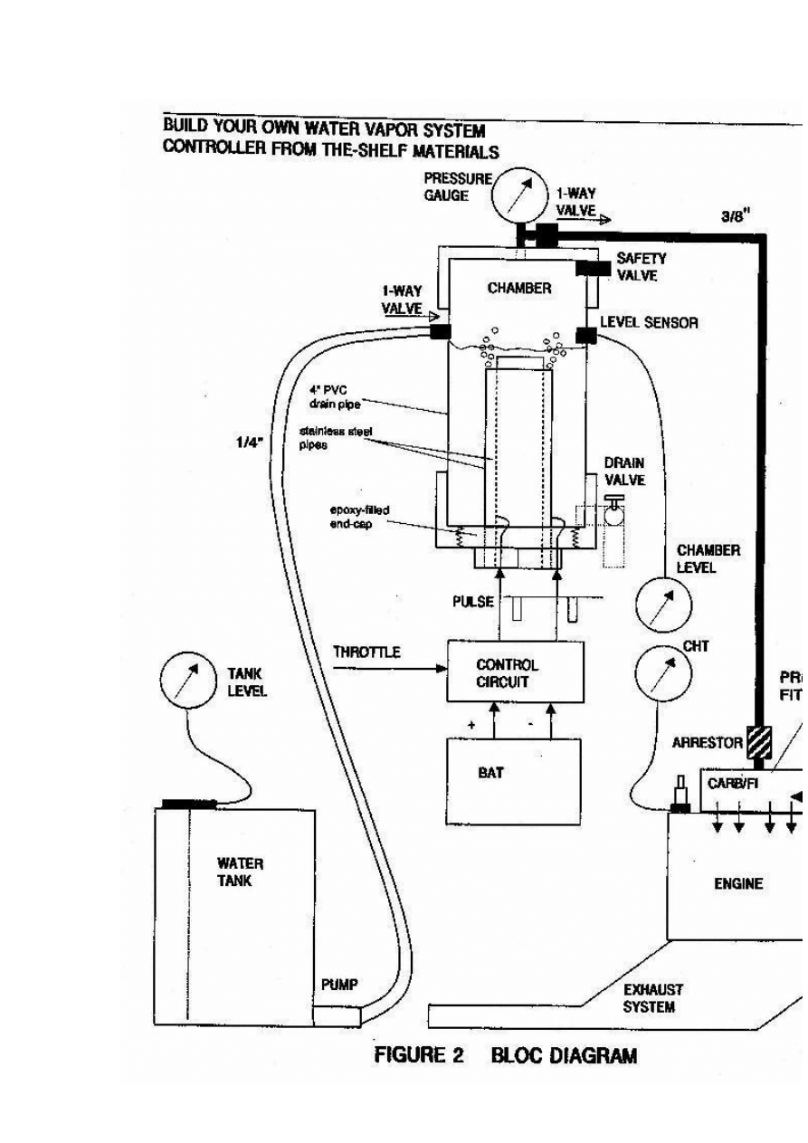
REACTION CHAMBER
Construct as shown in Figure 2. Use a section of 4" PVC waste pipe with a
threaded screw-cap fitting on one end and a standard end-cap at the other.

Make sure to drill-and-epoxy or tap threads through the PVC components for all
fittings. Set and control the water level in the chamber so that it well submerses
the pipe electrodes; yet leave some headroom to build up the hydrogen/oxygen
vapour pressure.
Use stainless steel wires inside the chamber or otherwise use a protective coating;
use insulated wires outside. Ensure that the epoxy perfects the seal, or otherwise
lay down a bead of water-proof silicone that can hold pressure.
The screw fitting may require soft silicone sealant, or a gasket; its purpose is to
hold pressure and allow periodic inspection of the electrodes. No leaks, no
problems. Make sure you get a symmetric 1-5mm gap between the 2 stainless
steel pipes. The referenced literature suggests that the closer to 1mm you get, the
better. You WILL want to get your chamber level sensor verified BEFORE you
epoxy the cap on.
Make your solder connections at the wire/electrode junctions nice, smooth, and
solid; then apply a water-proof coating, e.g. the epoxy you use for joining the
pipes to the screw cap.
This epoxy must be water-proof and be capable of holding metal to plastic under
pressure.
You WILL want to get your chamber level sensor verified BEFORE you epoxy
the cap on.
CONTROL CIRCUIT
Figure 3
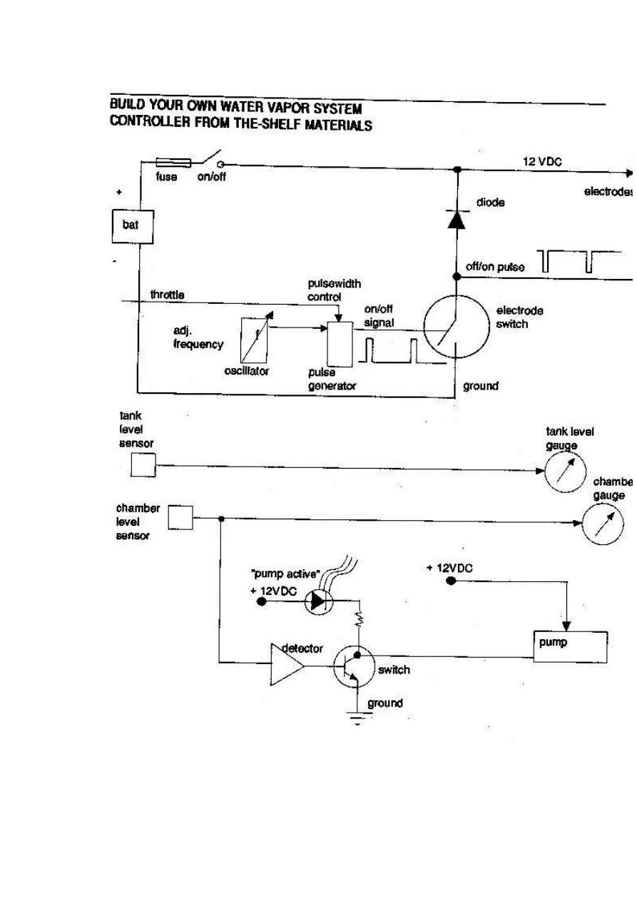
Figures 3 & 4 show a simple circuit to control and drive this mini-system. You
are going to make a 'square-pulse' signal that 'plays' the electrodes like a tuning
fork; which you can watch on an oscilloscope. The premise given by the
literature is:
The faster you want do go down the road, the 'fatter' you make the pulses going
into the reaction chamber. Duty cycle will vary with the throttle in the vicinity of
90%Mark 10%Space (Off/On).
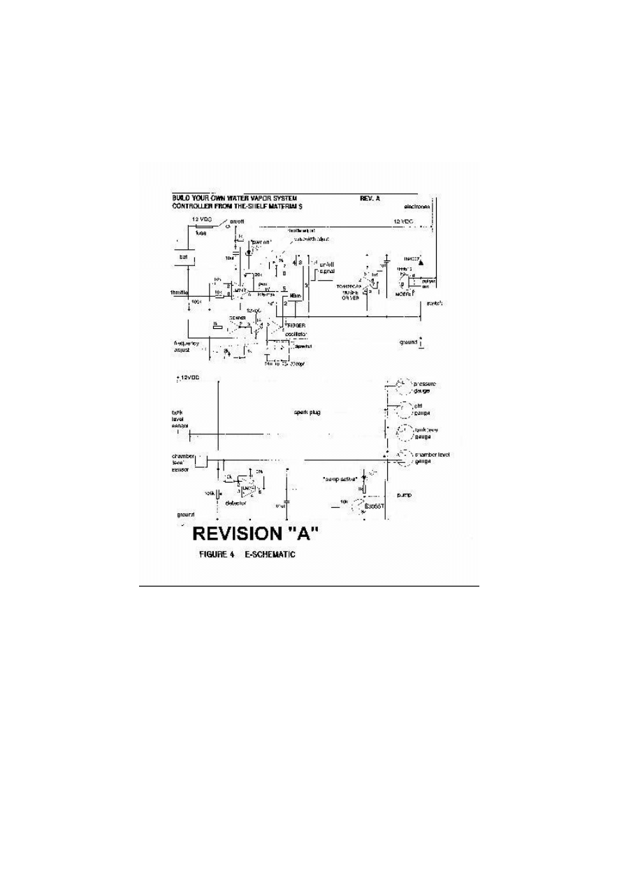
NOTE : Figures 4 and 5 have been revised, click to see the large version

There is nothing sacred about how the pulse waveform is generated; there are
many ways to generate pulses, and the attached diagrams show a few. Figure 4
gives the NE555-circuit approach from the referenced patent. The output
switching transistor must be rated for
1-5 amps @ I2VDC (in saturation).
Go with a plan that works for you or your friendly neighborhood technoid or
mechanic, and go get all the circuit elements from your local electronics store,
such as Radio-Shack or Circuits-R-Us, including the circuit board, IC sockets,
and enclosure/box.
DigiKey has better selection, service, and knowledge; plus they have no
minimum order crap. Be sure to use a circuit board with a built-in ground plane,
and to accommodate room for mounting 2 or 3 of the gauges. Mounting the
reaction chamber in the engine compartment will require running a stub to your
pressure gauge where you can watch it.
You can easily make 30-gauge wire-wrap connections between the socket pins
and through-hole discrete components having wire leads. Also make sure to get
spec sheets on any IC you use. More details of the best circuits to use will be
announced pending prototype testing. You WILL want to get your chamber level
sensor verified BEFORE you epoxy the cap on.

THROTTLE CONTROL
If you have a throttle position sensor, you should be able to access the signal
from the sensor itself OR from the computer connector. This signal is input to
the circuit as the primary control (i.e. throttle level pulse width = vapour rate).

If you don't have such a signal available, you will have to rig a rotary POT
(variable resistor) to the gas linkage (i.e. coupled to something at the gas pedal or
throttle cable running to the carb or Fl. If you make the attachment at the
cart/Fl, be sure to use a POT that can handle the engine temp cycles. Don't use a
cheezy-cheapy POT; get one rated for long life and mechanical wear; mount it
securely to something sturdy and stationary that will not fall apart when you
step on the gas.
CONTROL RANGE
The full throttle RANGE (idle-max) MUST control the vapour rate, i.e. pulse-
width (duty). The resistor values at the throttle signal must allow the throttle
signal voltage, say 1-4 Volt swing, to drive the VAPOR RATE. You will be using
this voltage swing to generate a 10% ON 'square' pulse.
The patent implies using a 'resonant' pulse in the 10-250 KHz frequency range;
but it is not explicitly stated so. In this circuit, you will simply tune to whatever
frequency makes the most efficient vapour conversion. You will have to get into
the specs for each IC you use, to insure you connect the right pins to the right
wires, to control the frequency and pulse width.
You can use spare sockets to try out different discrete component values. Just
keep the ones that are spec-compatible in the circuit, and get the job done.
You crank up the throttle signal and put more electrical energy (fatter pulses)
into the electrodes; verify you can get 10% duty on the scope (2 - 100 usec on the
horizontal time-base). Your averaging DVM will display the 90%-I 0% DC
voltage across the output transistor (Vce or Vds or Output to Ground). Set and
connect DVM in the supply current and measure .5 - 5 amps, without blowing
the DVM fuse. Now verify that you got everything you wanted.
Verify your wiring connections using your DVM as a continuity detector. Check
your wiring 1 at a time and yellow line your final schematic as you go. You can
best use board-mount miniature POTs for anything you want to set-and-forget.
The LEDs are there to give you a quick visual check of normal vs abnormal
operation of your new creation. You WILL want to get your chamber level
sensor verified BEFORE you epoxy the cap on (see Figures 2 & 4).
Figure 2 also shows that fittings are required to the carb/FI I. There are ready-
made kits (such as by Impco) available for making your pressure fittings to the
carburetor or fuel-injector as the case may be. You will necessarily be sealing the
built in vents and making a 1-way air-intake.
The copper mesh comprises the inadvertent backfire' protection for the reaction
chamber. Make sure that all vapor/duct junctions are air-tight and holding full
pressure without leakage. Your new 'system' is considered successful and
properly adjusted when you get the full power range at lower temp and
minimum vapor flow without blowing the pressure safety valve.

CHT (or EGT)
Monitor your engine temp with the CHT (cylinder head temp) or EGT (exhaust
gas temp) instead of your original engine temp indicator (if any). Your existing
gauge is TOO SLOW for this application and will not warn you against
overheating until after you have burnt something.
Make sure that your engine RUNS NO HOTTER than in the gasoline
arrangement. VDO makes a CHT gauge with a platinum sensor that fits under
your spark plug against the cylinder head (make sure it is REAL CLEAN before
you reinstall your spark plug (as this is also an electrical ground).
ENGINE/EXHAUST TREATMENT
Get the valves replaced with stainless steel ones AND get the pistons/cylinders
ceramic-treated ASAP when you have successfully converted and run your new
creation. Do not delay as these items WILL RUST, either by sheer use or by
neglect (i.e. letting it sit). You could make max use of your current exhaust
system by using it with your new deal until it rusts through, then have your
mechanic or welder friend to fit a stainless steel exhaust pipe (no catalytic
converter is required). But it could be ea$ier to send your existing exhaust
system out for the ceramic treatment, and then simply re-attach it to the exhaust
ports.
GENERAL
1. Do not discard or remove any of the old gasoline set up components, e.g. tank,
carb/FI, catalytic converter, unless necessary. Better to always leave an easy way
to revert back to something that at least runs, just in case. Some people are
leaving their gasoline set up completely intact, and switching back and forth at
will, just to have a backup plan.
2. Set your throttle circuit so that you get minimum vapour flow at IDLE, and
maximum vapour flow at FULL POWER without blowing the pressure relief
valve. In this way, you control how 'lean' your mixture is by the strength of the
pulse (i.e. 'fatness' at the optimum pulse frequency).
If you just don't get enough power (at any throttle setting), it means that you
need to
•
(1) change the pulse frequency,
•
(2) change the gap between the electrodes,
•
(3) change the size (bigger) electrodes, OR
•
(4) make a higher output pulse voltage (last resort).
Always use an output transistor, such as a MOSFET, that is rated for the voltage
and current you need to get the job done. OK so you might have to play around
with it some. Isn't that where all the Fun is anyhow?

If you get ANY engine knock our loud combustions (not compensated by
adjusting the timing), it means that you need to install an additional coil in the
chamber, and drive the coil with an additional pulse signal (about 19 Hz on the
.lsec time base) (see Figure 5).
Here,you will be slowing down the burn rate just enough so that the vapours
burn throughout the power stroke of the piston. Be sure to include a board-
mount POT to set the correct strength of this 2nd pulse signal into the coil. This
is a stainless steel coil of about 1500 turns (thin wire) that you can arrange like a
donut around the center pipe (but NOT touching either electrode), directly over
the circular 1-5mm gap. You want NO KNOCKING at any power/throttle
setting; smooth power only, but also no excess hydrogen leftover from the
combustion.
5. Build the canister(s) as tall as you can without compromising your ability to
mount them conveniently near the dash panel, or in the engine compartment, as
the case may be. This way, you can always make the electrodes bigger, if
necessary without undue hardship. Remember that anything in the engine
compartment should be mounted in a bullet-proof, vibration and temperature
tolerant fashion.
6. If you have to drill a through-hole for wiring or plumbing through metal,
make sure to also install a grommet for protection against chafing. Always watch
your chamber pressure range from
IDLE (15-25 psi) - FULL POWER (30-60 psi) - Set your safety-pressure relief-
valve to 75 psi and make sure it's rated for much higher.
7. Shut OFF the power switch and pull over if there is any MALFUNCTION of
the system. Your engine will last longest when it still develops FULL POWER+
at some minimum temperature that we are sure you can find, by leaning back
the Royal Vapour Flow and/or by making use of the water-vapour cooling
technique (see Figure 7). Keep good mpg performance records, and periodic
maintenance/inspection. Keep it clean; save some money; clean the air; heal the
planet; happy motoring; tell a friend; enjoy your freedom and self-
empowerment; haul ass.
8. There lacks documented material for perfecting this vapour system through a
fuel injector; there may be some details you will discover on your own as
working prototypes progress. For example, you may be restricted to inject the
hydrogen/oxygen vapour WITHOUT ANY water vapour, as it may rust the
injectors. If engine temp and CHT is a problem, then you will want to re-think
your plan, e.g. ceramic-coating the injectors. There is always 'replacing the Fl
system with a Carb'.
9. If you install the water-vapour system (for lower operating temp/stress), you
will want to lean the mixture (vapour/air) for minimum vapour flow rate to
achieve any given throttle position (idle - max). Make sure that you get a
minimum flow for IDLE an a modestly sufficient flow for MAX, that does the
cooling job without killing the combustion.

10. If you cannot find stainless steel pipe combinations that yield the 1-5mm gap,
you can always regress back to alternating plates of +/- electrodes.
11. If you are concerned about the water freezing in your system, you can (a) add
some 98% isopropyl alcohol and re-adjust the pulse frequency accordingly; or
(b) install some electric heating coils.
12. Do not let ANYONE ever compromise your dream, your freedom, your
independence, your truth.
REFERENCES
1. Stephen Chambers
'Apparatus for Producing Orthohydrogen and/or
Parahydrogen' US Patent 6126794
2. Stanley Meyer
'Method for the Production of a Fuel Gas' US Patent 4936961
3. Creative Science & Research, 'Fuel From Water', fuelless.com
4. Carl Cella 'A Water-Fuelled Car'
Nexus Magazine
Oct-Nov 1996
5.
Peter Lindemann's Free Energy site
and his article from NEXUS
'Where in the World is All the Free Energy'
6.
George Wiseman's Eagle Research
'The Gas-Saver and HyCO Series'
7. C. Michael Holler 'The Dromedary Newsletter' and 'SuperCarb Techniques'
8. Stephen Chambers
'Prototype Vapor Fuel System'
DISCLAIMER: The author of this document assumes no liability for the use or
misuse of this information; which is made available as public-domain
information, for the purposes of education, ecology, health, well-being, freedom,
liberty, and pursuit of happiness.
COMMON LAW COPYRIGHT #285714: All rights to the use and duplication
of these plans are hereby reserved for the People, in their efforts to heal and
restore the environment. Dare to express your uniqueness and environmental
ideals. This technology is an exercise in responsible self-determination.
Thank you for your purchase, please leave me your positive feedback and after I
will leave you the same feedback enjoy!
Thank you Take care Best Regards U.M.S

Wyszukiwarka
Podobne podstrony:
Fuel from Water e book
Fuel From Water Patent
Fugue no 12 from WTC book 1
Fugue V from WTC book 2
Fugue V from WTC book 1
Fuel from nothing Experiments of German chemists of the World War II
Make Me Whole A BWWM Pregnancy Romance (Brothers From Money Book 3) by Shanade White
Bach Fugue XVI from WTC book 2
Aspden POWER FROM WATER COLD FUSION PART 1 (1994)
Fugue IX from WTC book 2
Haendel Suite From Water Music
Bleaching Water Stains from Furniture
Bleaching Water Stains from Furniture
why Poland Director Professor Krzysztof Koehler from the Polish Book Institute
Get Your Ass in the Water & Swim Like Me African American Narrative Poetry from the Oral Tradition
RADIOACTIVE CONTAMINATED WATER LEAKS UPDATE FROM THE EMBASSY OF SWITZERLAND IN JAPAN SCIENCE AND TEC
Economics of Producing Fuel Pellets From Biomass
clean water cadets coloring book
back to school counting flip book from mrs fulbright
więcej podobnych podstron