
ARMY TM
AIR
FORCE AFM 88-9
5-811-3
CHAP. 3
ELECTRICAL DESIGN
LIGHTNING AND STATIC
ELECTRICITY PROTECTION
D E P A R T M E N T S O F T H E A R M Y A N D T H E A I R F O R C E
M A R C H 1 9 8 5

REPRODUCTION AUTHORIZATION/RESTRICTIONS
This Manual has been prepared by or for the Government and is pulic property and not subject to
copyright.
Reprints or republications of this manual should include a credit substantlly as follows" Joint Departments of
the Army and Air Force USA, Technical Manual TM 5-811-3/AFM 88-9, chpater 3, Electrical Design Lightning
and Static Electricity Protection."

*TM 5-811-3
AFM 88-9, Chap. 3
Technical Manual
No. 5-811-3
Air Force Manual
AFM 88-9, Chapter 3
DEPARTMENTS OF THE ARMY
AND THE AIR FORCE
Washington, DC, 29 March 1985
ELECTRICAL DESIGN
LIGHTNING
AND STATIC ELECTRICITY PROTECTION
CHAPTER 1.
GENERAL
Purpose . . . . . . . . . . . . . . . . . . . . . . . . . . . . . . . . . . . . . . . . . . . . . . . . . . . . . . . . . .
Scope . . . . . . . . . . . . . . . . . . . . . . . . . . . . . . . . . . . . . . . . . . . . . . . . . . . . . . . . . . . . . . . . . .
Application . . . . . . . . . . . . . . . . . . . . . . . . . . . . . . . . . . . . . . . . . . . . . . . .
General . . . . . . . . . . . . . . . . . . . . . . . . . . . . . . . . . . . . . . . . . . . . . . . . . . . . . . . . .
Applicable codes and standards . . . . . . . . . . . . . . . . . . . . . .
Design development . . . . . . . . . . . . . . . . . . . . . . . . . . . . . . . . .
Approved type systems.....,..,.. . . . . . . . . . . . . . . . . . . . . . . . . . . . . . . . .
Materials . . . . . . . . . . . . . . . . . . . . . . . . . . . . . . . . . . . . . . . . . . . . . . . . . . . . . . . . . . . . . . .
CHAPTER 2.
LIGHTNING PROTECTION
Discussion . . . . . . . . . . . . . . . . . . . . . . . . . . . . . . . . . . . . . . . . . . . . . . . . . . . . . . . . .
Limitations in use of lightning protection . . . . . . . . . . . . . . . . . . . . . . . . . . . . . .
Air terminals . . . . . . . . . . . . . . . . . . . . . . . . . . . . . . . . . . . . . . . . . . . . . . . . . .
Grounding . . . . . . . . . . . . . . . . . . . . . . . . . . . . . . . . . . . . . . . . . . . . . . . . . . . . . . . . .
Nonreinforced concrete or wood frame buildings . . . . . . . . . . . . . . . . . . . . . . . . . . . . . . . . . . . . . .
Reinforced concrete buildings . . . . . . . . . . . . . . . . . . . . . . . .
Steel frame building with nonconducting roof and sides . . . . . . . . .' . . . . . . . . . . . . . . . . . . . . . . . . . . . .
Metal clad building with steel framing . . . . . . . . . . . . . . . . . . . . . . . . . . . . .
Building containing hazardous areas . . . . . . . . . . . . . . . . . . . . . . . . . . . . . . . .
Classified communications building . . . . . . . . . . . . . . . . . . . . . . . . . . . . . . .
Aircraft control-navigation aids..., . . . . . . . . . . . . . . . . . . . . . . . . . . . . . . . .
Igloos . . . . . . . . . . . . . . . . . . . . . . . . . . . . . . . . . . . . . . . . . . . . . . . . . . . . . . . . .
Fences . . . . . . . . . . . . . . . . . . . . . . . . . . . . . . . . . . . . . . . . . . . . . . . . . . . . .
Railroads . . . . . . . . . . . . . . . . . . . . . . . . . . . . . . . . . . . . . . . . . . . . . . . . . . . . .
Weapon system electronic facilities above ground . . . . . . . . . . . . . . . . . . . . . . .
Weapon system electronic facilities below ground . . . . . . . . . . . . . . . . . . . . . . . . .
Electrically-controlled target training system . . . . . . . . . . . . . . . . . . . . . . . . . . . .
Petroleum oil lubricants (POL) facilities . . . . . . . . . . . . . . . . . . . . . . . . . . . . . . .
CHAPTER 3.
STATIC ELECTRICITY PROTECTION
Discussion . . . . . . . . . . . . . . . . . . . . . . . . . . . . . . . . . . . . . . . . .
Applications . . . . . . . . . . . . . . . . . . . . . . . . . . . . . . . . . . . . . . . . . . . . . . . . . . . . .
General . . . . . . . . . . . . . . . . . . . . . . . . . . . . . . . . . . . . . . . . . . . . .
Bonding . . . . . . . . . . . . . . . . . . . . . . . . . . . . . . . . . . . . . . . . .
Grounding . . . . . . . . . . . . . . . . . . . . . . . . . . . . . . . . . . . . . . . . . . . . . . . . . . . . . . . . . . .
Hazardous locations . . . . . . . . . . . . . . . . . . . . . . . . . . . . . . . . . . . .
Petroleum oil lubricants (POL) facilities . . . . . . . . . . . . . . . . . . . . . . . . . . .
Weapon systems . . . . . . . . . . . . . . . . . . . . . . . . . . . . . . . . .
Classified communications buildings.. . . . . . . . . . . . .
Corrugated steel arch type igloos for storage of MB-1, GAM-87 and GAR cased propellant
type weapons . . . . . . . . . . . . . . . . . . . . . . . . . . . . . . . . . . . . . . . . . . .
Airplane parking aprons . . . . . . . . . . . . . . . . . . . . . . . . . . . . . . . . . . . . .
Airplane hangar floors . . . . . . . . . . . . . . . . . . . . . . . . .
Conductive flooring . . . . . . . . . . . . . . . . . . . . . . . . . . . . . . . . . . . . . . . . . . . . . .
APPENDIX A. REFERENCES . . . . . . . . . . . . . . . . . . . . . . . . . . . . . . . . . . . . . . . . . . . . . . . . . . . . . . . . .
Paragraph
1-1
1-2
1-3
1-4
1-5
1-6
1-7
1-8
2-1
2-2
2-4
2-4
2-5
2-6
2-7
2-8
2-9
2-10
2-11
2-12
2-13
2-14
2-15
2-16
2-17
2-18
2-1
3-2
3-3
3-4
3-5
3-6
3-7
3-8
3-9
3-10
3-11
3-12
3-13
Page
1-1
1-1
1-1
1-1
1-1
1-1
1-1
1-1
2-1
2-2
2-2
2-2
2-5
2-5
2-6
2-4
2-6
2-6
2-6
2-6
2-6
2-6
2-6
2-7
2-7
2-7
3-1
3-2
3-2
3-3
3-3
3-3
3-3
3-3
3-4
3-4
3-4
3-4
3-4
A-1
*This
manual supersedes TM 5-811-3, 28 August 1978.

TM 5-811-3/AFM 88-9, Chap. 3
CHAPTER 1
GENERAL
1-1. Purpose.
Information and criteria in this man-
ual will guide engineering design personnel in deter-
mining the adequacy of lightning and static electric-
ity protection systems for all types of facilities.
Policy and procedure of design development and
tests are also included. Referenced criteria, codes,
and standards are intended to include provisions for
normal type facilities, which when integrated with
criteria included herein, establish complete provi-
sions for these protection systems. The standards
and methods of system protection discussed are in-
tended as the most practical and economical means of
accomplishing protection of real property and avoid-
ance of casualties to personnel. These criteria will not
provide suitable protection for construction contrac-
tors’ personnel.
1-2. Scope
a. General. The scope of this manual will include
adequacy of engineering design for facilities of Army,
Air Force and other agencies in conformance with
paragraph 1-3.
b. Limitations. Limitations within continental
‘
United States will be subject only to specific provi-
sions of project design directives, deviations included
herein or authorized by HQDA (DAEN-ECE-E)
WASH DC 20314-1000, for Army projects, and
HQUSAF/LEEE WASH DC 20332, for Air Force
Projects.
c. Other protection systems. These criteria are not
intended to support or implement separate criteria
such as furnished for electromagnetic protection or
electromagnetic shielding requirements.
1-3. Application.
Except as included for facilities
of the Army Materiel Development and Readiness
Command, criteria contained in this manual will ap-
ply to new construction of permanent, fixed type fa-
cilities conforming to AR 415-15 within the continen-
tal United States. Where conflicts arise with criteria
or design guidance of different Army or Air Force
agencies, or with Federal organizations other than
Army or Air Force, the most stringent guidance will
govern. Criteria or design guidance will apply to
overseas facilities in conformance with AR 415-36.
1-4. General
a. Separate section of a specification. Inasmuch as
provisions for lightning protection involve a special
type (steeple jack) trade, contract requirements for
lightning and static electricity protection will be in-
cluded as a separate section in project specifications.
b. Environmental considerations. Design consid-
eration will be given to overall appearance so as to
maintain an attractive facility in harmony with area
surroundings.
c. System components. Components will conform
to applicable NFPA codes, except as otherwise
stated or indicated.
d. Penetration of building exterior surfaces.
Where roofing, walls, floor and waterproofing mem-
branes are penetrated by components of these sys-
tems, adequate waterproofing and caulking of such
penetrations will be provided. However such pene-
trations will be avoided whenever possible.
1-5. Applicable codes and standards.
Codes
and standards referenced in this manual and listed in
Appendix A are to be considered as an integral part
of this manual,
1-6. Design development
a. Lightning protection system. When contract
drawings comprise more than one sheet showing
composite roof and architectural elevation, a separate
sheet will be provided showing locations of air termi-
nals, routing of roof conductors, down conductors,
and grounding system pattern.
b. Static electricity protection system. Where
static electricity protection for two or more rooms or
areas is indicated on an architectural floor plan and
cannot be shown on an appropriate electrical plan, a
separate floor plan sheet showing the complete static
electricity protection system pattern will be included
in the project design.
1-7. Approved type systems
a. Lightning protection. Selection of the type of
protective system will be as prescribed in this man-
ual, NFPA No. 78, and MIL–HDBR-419.
b. Static electricity protection. Selection of system
t y p e w i l l b e p r e s c r i b e d i n N F P A N o . 7 7 ,
MIL-HDBR 419, and MIL-STD-188-124.
1-8. Materials.
Materials will conform to applicable
NFPA codes, unless otherwise stated. Normally,
copper materials will be specified for use below fin-
ished grade. Stainless steel grounding devices should
be used when there is a potential of galvanic corro-
sion of nearby steelpipes. UL listed compression-
type connectors may be used where such connectors
are equivalent to the welded type. Special considera-
tion will be given to selection of materials to compen-
1-1

TM 5-811–3/AFM 88–9, Chap. 3
sate for the following conditions as encountered at
corrosion. This must be prevented by use of same
project locations:
type metals, or by providing junctions of dissimilar
(1) Corrosive soils and atmosphere.
metals in air that will permanently exclude moisture.
(2) Atmospheric and ground contact corrosion.
(4) Equal mechanical strength or fusing capabil-
(3) Electrolytic couples that will accelerate cor-
ity where conductors of different metals are joined.
rosion in the presence of moisture or ground contact
1-2

TM 5-811-3/AFM 88-9, Chap. 3
CHAPTER 2
LIGHTNING PROTECTION
2-1. Discussion
a. Lightning phenomena. The planet earth is simi-
lar to a huge battery continuously losing electrons to
the atmosphere. These electrons could be lost in less
than an hour unless the supply is continually replen-
ished. It is widely agreed among physicists and scien-
tists that thunderstorms occurring thousands of
times daily around the earth return electrons to
earth to maintain normal magnitude of electrons at or
near the surface of- the earth. The rate of electron
loss from earth, called the “air-earth ionic current”,
has been calculated to be 9 microampere for every
square mile of earth’s surface. Thunderstorms supply
electrons back to earth by an opposite electron poten-
tial gradient of perhaps 10 kilovolts per meter within
a thundercloud. This feedback forms a potential dif-
ference of from 10 to 100 megavolts in a single dis-
charge between the center of a cloud and earth.
These lightning discharges carry currents varying
from 10 to 345 kiloamperes to earth at an average
rate of 100 times per second with duration of less
than ½ second per flash. Each flash consists of up to
40 separate strokes, Each stroke of lightning lasting
for this brief instant releases about 250 kilowatt-
hours of energy-enough to operate a 100-watt light
bulb continuously for more than three months at the
rated voltage of the lamp. Lightning discharges do
not always bring electrons to earth, because so-called
positive ground-to-cloud strokes consist of low power
energy transmissions from earth to small negative
charge pockets in a thunder cloud. However, magni-
tudes of discharge voltages and currents are approxi-
mately the same from cloud to earth, and all occur
within the same discharge timeframes. Just before
the lightning flash, the ground within a radius of sev-
eral miles below the cloud becomes deficient in elec-
trons. Repelled by the army of electrons in the cloud
base, many of the free electrons on the ground are
pushed away. The result is that the ground beneath
the cloud base becomes more positively charged. As
the cloud moves, the positive charge region below
moves like its shadow. As the cloud charge balloons,
the pressure becomes so great that a chain reaction
of ionized air occurs. Ionization is the process of
separating air molecules into positive ions and nega-
tive electrons. This air which is normally a good elec-
trical insulator becomes a good conductor and allows
the cloud electrons to pierce the faulted insulation
and descend this newly created ionized air path be-
tween cloud and earth. The lightning flash starts
when a quantity of electrons from the cloud heads to-
ward earth in a succession of steps, pulsing forward
with an additional step every 50 microseconds
creating a faintly luminous trail called the initial or
stepped leader. As the leader nears the ground, its
effects create an ionized streamer which rises to
meet the advancing leader. When the two join, the
ionized air path between cloud and earth is
completed, and the leader blazes a faint trail to
earth. Immediately a deluge of electrons pour from
this lightning discharge channel creating the brilliant
main or return stroke that produces most of the light
we see, The motions of the leader and the main or re-
turn stroke appear to move in opposite directions,
but lightning is not an alternating current, since the
transferred electrical recharge current moves back to
earth.
b. Nonconventional systems. Nonconventional and
unacceptable systems include the so-called dissipa-
tion array, and those using radioactive lightning
rods, Radioactive lightning rods have been proven
less effective than passive air terminals in storm situ-
ations. These systems have not been recognized by
NFPA or UL. Use of these systems will not be
permitted unless specifically approved by the appro-
priate using agency. Dissipation arrays consist of two
types:
(1) A high tower with top-mounted dissipation
suppressor, and radial guy wire array. This type is
used on isolated high towers, antenna structures and
offshore facilities.
(2) A series of high towers located beyond a
given area to be protected and supported by a num-
ber of sharp pointed strands of barbed wire for the
protection array.
c. Code applicability. NFPA No. 78 is intended to
apply to the protection of ordinary buildings, special
occupancies, stacks, and facilities housing flammable
liquids and gases. The lightning protection code will
be utilized where lightning damage to buildings and
structures would cause large economic loss or would
prevent activities essential to the Department of De-
fense. NFPA No, 78 does not relate to the protection
of explosives manufacturing or storage facilities. Pro-
tection for these facilities will be in accordance with
paragraph 2–9. Since NFPA No. 78 does not pre-
scribe a comprehensive coverage pattern for each
type of facility required by the military departments
of the government, additional guidance is given in
this chapter. Temporary DOD storage facilities and
structure housing operations not regularly conducted
at a fixed location and other facilities specifically ex-
2-1

TM 5-811-3/AFM 88–9, Chap. 3
empted by the responsible using agency are not gov-
erned by the lightning protection code.
d. Effects of lightning discharges.
(1) General. When any building or structure is
located within a radius of several hundred feet from
the point where a lightning discharge will enter the
surface of the earth, the lightning discharge current
becomes so high that any building or structure within
this radius becomes vulnerable to immediate damage.
(2) Nature of damage. Damage may range from
minor defacement to the building to serious founda-
tion upheaval, fire and personnel casualties. Damage
control can be effective dependent on extent of fire-
proofing and lightning protection incorporated into
the project design. Although lightning strokes gener-
ate static discharges in the form of radio noise, it is
generally accepted that these cause only an instant of
interference to manmade electronic systems. In-
creased heating effects are also a factor since a light-
ning bolt increases the temperature of the lightning
channel to about 15,000 degrees C. This sudden in-
crease in temperature and pressure causes such an
abrupt expansion of air that any hazard type of at-
mosphere which comes within the ionized air path of
the lightning bolt becomes explosive. The explosive
nature of the air expansion of bolt channels can cause
physical disruption of structures located near the
lightning stroke. Lightning discharges below the
earth surface sometimes fuse sand into fulgurates
which appear like glass tubes. Trees of 40 feet or
more in height are especially vulnerable targets for
attraction of lightning discharges, and are susceptible
to being totally destroyed.
e. Effective resistance to ground.
(1) The lightning protection system will be de-
signed to provide an electrical path to ground from
any point in the system, and that point will be of con-
siderably lower resistance than that otherwise avail-
able by use of the unprotected facility.
(2) Low resistance to ground is desirable for any
lightning protection system but not essential. This is
in conformance with NFPA No. 78 and MI L–HDBK–
419. Where low resistance to ground is mandatory,
grounding electrode patterns as described herein and
MIL-HDBK-419 will furnish ample length of electri-
cal path in contact with earth to dissipate each light-
ning discharge without damage to the protected
facility.
2–2. Limitations in use of lightning protection
a. General. Lightning protection will be installed
as part of the initial construction project, particularly
in view of long replacement time and high cost of
structures. Installation cost of lightning protection
systems during project construction is small when
compared to the cost of the installation as a whole.
Economic and operational considerations will be
made in determining the need for lightning protec-
tion system, unless otherwise directed by the using
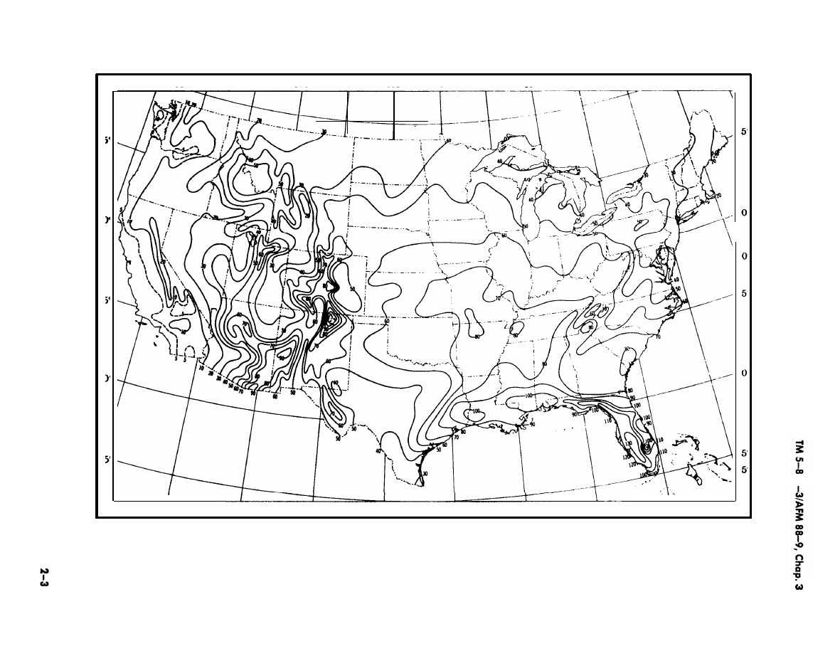
agency. Unless lightning frequency at the project
site averages five or less thunderstorms per year, as
indicated in figure 2-1, lightning protection will be
provided for buildings and structures as follows:
(1) Buildings of four floors having elevator or
stairwell penthouses or other similar projections
above roof.
(2) Buildings of five floors or more with or with-
out projections above roof.
(3) Structures such as steel towers, aluminum
and reinforced concrete towers, and flagpoles with-
out inherent grounding, and smoke-stacks and stee-
ples of 50-foot elevation or more above lowest point
of contact with finished grade.
b. Other applications. Special consideration will be
given in determining need for lightning protection as
follows:
(1) Whether building is manned, and there is in-
herent hazard to personnel.
(2) Whether building contains explosive or haz-
ardous areas or rooms, weapons systems technical
equipment, or security communication equipment.
(3) If an unprotected building is destroyed by
lightning, the length of outage which can be tolerated
until replacement is made. This includes the restora-
tion of high priority facilities such as water supply,
weapons systems, police and security intelligence
communications, strategic communication system op-
erating components.
(4) Replacement of building contents and value
thereof.
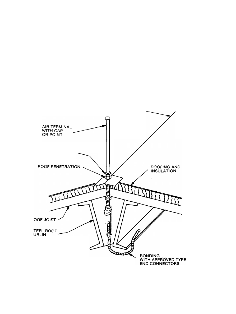
2–3. Air terminals.
The purpose of air terminals is
to intercept lightning discharges above facilities. Air
terminals will be in accordance with UL 96, and 96A,
NFPA No. 78 or MIL–HDB-419. Where building
roof is not metal and building construction includes
steel framing, air terminal connection assemblies will
conform generally to figure 2-2.
2-4. Grounding
a. General. Grounding generally will conform to
NFPA No. 78, except as required by this manual or
by the using agency. Guidance for grounding for pur-
poses, such as electromagnetic pulse (EMP), electro-
magnetic interference shielding, NASA and HQDCA
electronic facility grounding, are subjects of other en-
gineering manuals which govern grounding require-
ments. Those grounding systems will also serve as
grounding of the lightning protection system. Where
separate systems are installed such systems will be
bonded below grade to any other independently in-
stalled exterior grounding system such as for electro-
2-2
125° 50° 120°
115°
110°
105”
100”
95°
90°
85°
80°
75° 50° 70”
65°
115”
110°
105°
100”
95°
90°
85°
80”
National Oceanographic and Atmospheric Administration
Figure 2-1. Mean number of thunderstorms--annual
TM 5-811-3/AFM 88–9, Chap. 3
magnetic shielding not suitable for complete lightning
protection system. However, exterior protection
grounding system will be bonded to static electricity
exterior grounding system.
b. Ground rods. Ground rods will be not less than
10 feet in length, nor less than ¾-inch diameter pipe
or equivalent solid rod. Ground rods will be located
clear of paved surfaces, walkways, and roadways.
Rods will be driven so that tops are at least six
inches below finished grade, and three to eight feet
beyond perimeter of building foundation. Where
ground rods are used with a counterpoise, tops will
be driven to same elevation as counterpoise below
finished grade. Exact location of rods must give pref-
erence to use of moist earth. Contact with chemically
injurious waste water or other corrosive soils wiIl be
avoided. Where avoidance of chemically injurious or
corrosive soils is impracticable, use of stainless steel
rods and magnesium-anode protection will be consid-
ered. Driving stud bolts will be used for driving, and
couplings will be used for sectional rods. Where
buried metal pipes enter a building, the nearest
ground rod will be connected thereto.
c. Earth electrode subsystem. Each earth electrode
subsystem or counterpoise will consist of one or more
closed loops or grid arrangement of No. 1/0 AWG
bare copper conductors installed around facility pe-
rimeter not less than 2 feet below earth surface.
Larger conductors should be used when installed in
highly corrosive soils. A second loop, if used, should
not be less than 10 feet beyond the first and inner
loop. At least 2 ground rods should be provided at
each corner of each counterpoise loop where earth-
seeking current tend to concentrate. Counterpoise
ROOF RIDGE
LOCK NUTS OR
COUPLING
R
s
P
CONDUCTOR
US Army Corps of Engineers
Figure 2–2. Typical air terminal assembly using steel, framing as
protective system conductor
2 - 4
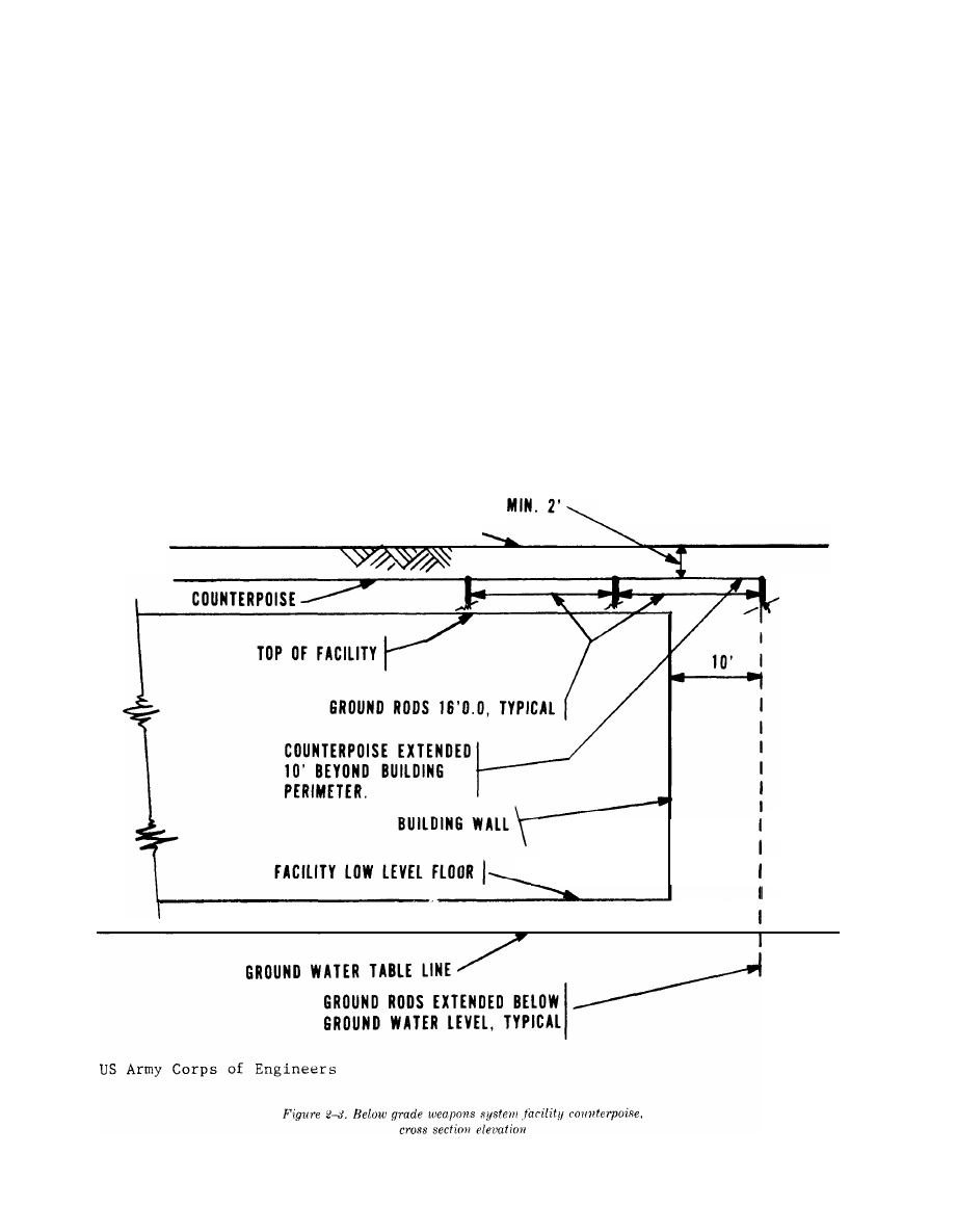
will extend not less than 3 feet nor more than 8 feet
beyond the perimeter of building walls or footings.
Conductor ends, connections to down conductors,
tops of ground rods
j
and crossovers will reconnected
for electrical continuity. Figure 2-3 illustrates a be-
low grade weapons system facility counterpoise. Pat-
tern will be as required in this manual or as required
by using service.
d. Radials. A radial system of grounding consists
of one or more No. 1/0 AWG copper conductors not
less than 12 feet long, extending away from each
ground rod or grounding connection. The use of mul-
tiple radials is an effective form of grounding, offer-
ing substantially lower reactance to the high fre-
quency of lightning current wave fronts than do
single straight conductors. Installation of grounding
radials will take advantage of crags and cracks in
surface rock formations in obtaining maximum avail-
able earth cover. Connections of radials to down con-
ductors will be made so as to insure electrical
continuity.
F I N I S H E D G R A D E
TM 5-811-3/AFM 88–9, Chap. 3
2-5. Nonreinforced concrete or wood frame
buildings.
Lightning protection will be provided on
outside of exterior surfaces without reliance upon
components of building for conductors. Fasteners for
conductors will be other than aluminum on concrete,
and will be selected for attachment to building con-
crete or wood.
2–6. Reinforced concrete buildings.
Reinforce-
ment steel may be used for down conductors in con-
formance with NFPA No. 78 and if approved by the
using agency. Joints should be made in no fewer than
every fifth reinforcement rod and at corners of build-
ing. Joints will be made electrically conductive and
will be connected top and bottom for connections to
roof conductors and to grounding electrodes, respec-
tively. Grounding pigtails from bottoms of reinforce-
ment fabric will be connected to exterior grounding
system at same or lower elevation as that where pig-
tails leave walls and footings.
2 - 5

TM 5–811–3/AFM 88–9, Chap. 3
2-7. Steel frame building with nonconducting
roof and sides.
Air terminals will be provided and
installed in conformance with figure 2-2 and para-
graph 2-3. Not less than one steel column will be
grounded at each corner of building.
2–8. Metal clad building with steel framing.
Steel columns of metal clad buildings will be bonded
top and bottom to metal siding. Except for facilities
used for storage of propellant type weapons and un-
less the using service guidelines or requirements dif-
fer, air terminals may be omitted from building con-
taining no hazardous areas.
2 – 9 . B u i l d i n g c o n t a i n i n g h a z a r d o u s a r e a s .
Metal containers of hazardous materials will not be
located within 10 feet of lightning protection system.
Any metals within hazardous atmospheres having
connections to other metals within 10 feet of light-
ning protection system will be bonded to the nearest
lightning protection system down conductor. Metal
doors and windows within hazardous areas will be in-
cluded in such grounding, and doors will be bonded to
metal framing by flexible braid-type copper conduct-
ors, and connected to lightning protection system.
2–10. Classified communications building.
Lightning protection and grounding of communica-
tions facilities will comply with MIL-STD-188-124
and MI L–HDBK-419.
2–1 1. Aircraft control-navigation aids.
a. General. These facilities are considered of such
importance that aircraft pilots must be assured of re-
liability, particular when landing during any light-
ning storm, and when pilot’s visibility is severely lim-
ited. Counterpoise grid g-rounding system will be
provided for each building.
b. Instrument landing system (ILS), tactical air
navigation (TACAN) and ground control approach
(GCA), facilities. One-floor frame buildings housing
equipment for ILS and TACAN facilities and other
similar type structures will be protected as described
in paragraph 2-5; however no fewer than two air ter-
minals will be provided on each facility. Transmitter
and receiver buildings for GCA facilities will be pro-
tected as described in paragraph 2-6.
c. Control towers. Protection will be provided inde-
pendently of antennas and other superstructure.
These terminals will be interconnected around top
perimeter of control tower for connections to down
conductors.
2–12. Igloos.
Protection for corrugated steel arch
earth-mounted igloos, also called “magazines”, will be
provided as required by the using agency. Metallic
conduits containing electrical conductors will be
bonded to steel arch, and all will be grounded in con-
formance with paragraph 24.
2–13. Fences.
Metal fences that are electrically
continuous with metal posts extending at least 2 feet
into the g-round normally require no additional
grounding. Other fences should be made electrically
continuous and grounded on each side of every gate.
Fences should all be grounded every 1,000 to 1500
feet when located in isolated areas; and every 500 to
750 feet when located within 100 feet of public roads,
highways and buildings. All metal fences will be
grounded at or near points crossed by overhead
powerlines in excess of 600 volts and also at distances
of 150 feet on each side of the line crossing.
2–14. Railroads.
Rails that are not electrically con-
tinuous and that extend within 100 feet of facilities
used for storage, manufacturing, processing or han-
dling explosives, explosive ingredients. explosive
gases, or flammable liquids will be bonded together
with flexible copper cables or straps and grounded.
Switches will be bonded to rails. Where overhead
power lines in excess of 600 volts crosses railroads,
the rails will be made electrically continuous and
grounded at a distance of 150 feet on each side of
overhead lines. Where tracks are located within 25
feet of structures with a grounding system, the
tracks will be grounded to the structural grounding
system. This is to effectively discharge potentials
generated by static electricity and lightning before
such discharges are permitted to accumulate or oth-
erwise cause an air gap spark to ignite loose hazard-
ous materials. Isolation points should be provided in
the tracks outside of hazardous areas to avoid stray
currents from being conducted into the bonded or
grounded area.
2–15. Weapon system electronic facilities
aboveground
a. General. This guidance pertains to designs for
the protection of radars, antennas, electronic equip-
ment vans, launchers, missile controls, and guided
missile batteries when permanently installed. Any
lightning stroke may damage or destroy such elec-
tronic weapon facilities by blast effect or by creating
surges in connecting wiring. A direct stroke could ig-
nite magnesium portions of van walls, cabinets, con-
soles, and radar antenna castings. When lightning oc-
curs with rain, moisture encourages burning of
magnesium and splattering of molten metal. Protec-
tion for weapon support buildings is as required by
construction types discussed in previous paragraphs.
b. Protection pattern. Patterns will comply with
NFPA No. 78. When structure is a van type, pole
will be located opposite middle of van’s longest side,
and not less than 6 inches from concrete base of van
2 - 6
TM 5-811–3/AFM 88-9, Chap. 3
to pole. One pole may serve two van units having
long sides parallel and located not more than 12 feet
apart. Protection equipment will be located and
arranged in a manner that will not obstruct the oper-
ation of any radar electronic acquisition or tracking
beam.
c. Protection system. Down conductors of not less
than No. 2 AWG bare copper on pole will be pro-
vided from lightning rod to ground rods located not
less than 6 feet from van and not less than 6 inches
from edge of hardstand. Spiral type grounds under
poles (butt grounds) are acceptable. Pole guys will be
electrically conductive to ground, and guy anchor will
be interconnected to pole ground rod below grade.
Each ground rod at pole will be interconnected below
hardstand to ground rod of’ van grounding system.
Where vans are clustered, van ground rods will be
interconnected in compliance with MIL-HDBK-419.
2–16. Weapon system electronic facilities be-
low ground
a. Protection included with other protection sys-
tems. When external grounding system design is in-
cluded for electromagnetic pulse (EMP) protection,
electromagnetic interference shielding or other pro-
tection system, separate lightning protection will not
be required.
b. Protection not included in other protection sys-
tems. When external grounding system design does
not include EMP protection, electromagnetic inter-
ference shielding or other protection system, light-
ning protection counterpoise will be provided includ-
ing connections to metallic objects below grade, such
as the following:
(1) Electrical conduit.
(2) Mechanical piping.
(3) Metal tanks.
(4) Manhole grounds.
(5) Missile cells or equivalent.
(6) Internal grounding system of control build-
ings and power plants.
(7) Metal ducts for fans.
(8) Tunnels.
The main counterpoise will be installed above each
buried weapon system building, at least 2 feet below
finished grade, and will extend beyond the building
perimeter not less than 3 nor more than 8 feet. Main
counterpoise will be connected to ground rods located
as in figure 2–3, and driven to a point at least 6
inches below normal ground water table level, where
earth is available for driving. See also above for
building reinforcement system grounding. Metal
equipment extending above ground will be grounded
to protection system counterpoise.
2–17. Electrically-controlled target training
system
a. General.
Reliability of continuous operational
availability of electricallty-cont rolled target systems
for rifle squad tactical ranges is of such importance to
infantry training in the scheduling of firing periods
and to morale of’ large numbers of troops that provi-
sions of lightning protection is warranted. Lightning
protection for rifle range support facilities need not
be provided.
b. Control tower. Complete protection system will
be provided. The system should have at least two air
terminals installed on roof.
c. Target control system. Where a control relay is
separately provided at each target mechanism box
assembly station of such rifle ranges, lightning pro-
tection counterpoise or grid will not be required for
protection of down range target area. Where such
control relays are not provided, grounding counter-
poise or grid will be provided above wiring in
trenches below grade to all targets from control
tower.
2–18. Petroleum oil lubricants (POL) facilities
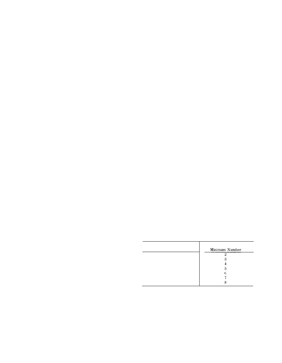
a. Storage tanks. Generally, protection for storage
tanks will depend on their inherent contact with
earth. Where steel storage tanks are constructed on
foundations of concrete or masonry, grounding will
be provided in accordance with grounding schedule
show-n in table 2–1, regardless of tank height. Where
steel tanks are constructed in direct contact all
around the perimeter with not less than 18 inches of
earth, grounding will not be required. See AFM
85-16 for additional requirements pertaining to Air
Force facilities.
Table 2-1. Fuel Storage Tank Grounding Schedule
Tank Circumference—Feet
200
And Less
201 Through 300
301 Through 400
401 Through 500
501 Through 600
601 Through 800
801 And More
Ground Connections
b. Pump house. Protection for POL pump house
will be provided complete as required for the applica-
ble type of building construction.
c. Fill stands. Protection for fill stands will con-
form to NFPA No. 78.
2 - 7
TM 5–811–3/AFM 88-9, Chap. 3
CHAPTER 3
STATIC ELECTRICITY PROTECTION
3–1. Discussion
a. General. While the practice of grounding electri-
cal systems is well established, the full implications
of static electricity protection are not always under-
stood. The object of static electricity protection is to
provide a means whereby static electricity charges,
separated by whatever cause, may recombine harm-
lessly before sparking charges are attained. In order
for a static electricity charge to become a source of
trouble, the following conditions must be considered:
(1) There must be a means of static generation.
(2) There must be a means of accumulation of a
static charge capable of producing ignition.
(3) There must be a means of spark discharge of
the accumulated charge.
(4) There must be an ignitable mixture or atmos-
phere at location of spark discharge to constitute an
explosive or fire hazard.
(5) The static potential must be maintained to
constitute a hazard to personnel.
(6) The static charge must be continuously con-
ducted to constitute a compromise of classified com-
munications. It may be impracticable to attempt miti-
gation or control of all static charges. Furthermore,
most static charges normally do not accumulate suffi-
cient charge to supply enough energy to produce a
spark capable of causing ignition. It should be recog-
nized, however, that when static electricity accumu-
lates, it becomes a potential hazard, and therefore
must be controlled as required. Electrostatic electric-
ity charges are generated by friction or contact be-
tween dissimilar conductive, semiconductive or
nonconductive moving objects, materials, liquids or
air particles. Obviously, we live in an electrostatic
environment containing constant movement of mole-
cules, none of which is inherently grounded. When
two solids move into contact, a voltage difference or
contact charge occurs. In most cases it is very small,
but with tin and iron, as specific examples, it is
nearly a third of a volt. The tin is electropositive in
this case. Moreover, if a piece of plastic is merely
pressed—not rubbed-against a metal plate and
taken away, it will have a charge where actual con-
tact was made. Whereas if the plastic is rubbed on
the metal, the charges will be increased in proportion
to the number of little areas which actually make con-
tact. The plastic, being a nonconductor, tends to re-
tain that state at any little area of contact. When an
insulating solid becomes charged, the charge tends to
remain anchored to the area where it was developed.
Good insulators having clean dry surfaces in low at-
mospheric humidity can hold their charge for quite a
while. A poor insulator quickly loses its charges to
surrounding areas, and a good insulator having sur-
face contamination will become somewhat conductive
regardless of humidity, and will permit leakage to
take place. A volume of relatively dry space which is
normally a good insulator containing neutral mole-
cules can also become charged by radioactivity andl
cosmic rays. However, since there are no known per-
fect insulators, isolated charges of static electricity
always eventually leak away. The problem is to pro-
vide instant control of hazardous accumulations of
static charges without reliance upon natural bleeding
or leaking away of such charges. For static electricity
to discharge as a spark, the accumulated charge must
be capable of jumping through a spark gap. The mini-
mum sparking voltage at sea level is generally ac-
cepted as approximately 350 volts for the shortest
measurable length of gap. Characteristics of the gap
are also a limiting factor. For discharge to constitute
a fire hazard, the gap must exceed a critical minimum
length to permit the buildup of a sufficient energy
level for an incendiary spark to result. Of course,
there must be an ignitable mixture in the gap where
the spark occurs. This energy level is estimated to be
in order of 10
-8
joules minimum. An example of
sparking voltages required to break clown various air
gap spacings is furnished in table 3–1. For calculating
ignition energy, refer to NFPA No. 77.
**Varies between 450 and 22,000 volts depending on air gap characteristics.
3-1

TM 5-811-3/AFM 88-9, Chap. 3
b. Sources of static electricity charges. For pur-
poses of this manual, static electricity charges should
be considered as being generated by three classifica-
tions of sources.
(1) Magnetic inductions.
(a) office equipment with moving parts as in
data processing systems, having integral electric
motor-driven parts assembled in a ferrous metal fire-
proof enclosure where the motors are grounded into
the building electrical distribution system.
(b) Portable, normally ungrounded, electric
motor-driven equipment having a ferrous metal en-
closure exposed to operating personnel. Induced
charges from magnetic induction sources could be of
continuous duration at utilization voltage of electric
motors.
(2) Electrostatics as defined in NFPA No. 77.
(3) Lightning static results from accumulations
of extremely high voltage discharges, as discussed in
paragraph 2–la. These magnitudes of potentials are
sufficient to break down the dielectric strength of air
for distances upwards of 3,000 feet, It will suffice to
note here that lightning discharges can and do by
their so-called side effects break down the dielectrics
of many man-made condensers (ungrounded insulated
metals, for example) existing within most of our
buildings, and thereby very rapidly generate hazard-
ous and explosive accumulations of static electricity
energy in these condensers.
c. NFPA No. 77. This code suggests special stud-
ies for determining the need to provide means of pre-
venting accumulation of static electricity in the hu-
man body. These studies include such means as:
conductive flooring, use of nonmetallic supports and
hardware for personnel assistance, and tie-down
rings for aircraft and hydrant refueling. These means
of static control are included below, as appropriate.
d. Effects of static electricity discharges. There are
many reasons why concerns for protection against
static electricity charges are important. Most of the
everyday, normal types of static charges find a quick
natural means of dissipation without any hazardous
effects. However, because static charges of instanta-
neous magnitudes greater than 10 kilovolts may be
encountered, it is mandatory that potential effects
from accumulations of these charges be considered.
This is particularly essential where personnel are in-
volved and where such static discharges may occur in
hazardous areas with sufficient strength to produce
ignition. It is not the intent herein to provide a list-
ing of effects of discharges of static electricity, as
many are already well known. It is the intent, how-
ever, to place every electrical designer on the alert to
use every reasonable precaution for including static
electricity protection in each project specification
when such protection is required.
e. Resistances to ground. Resistance to ground for
dissipation of static electricity charges is not critical
in order to provide adequate leakage path to ground
and to equalize static electricity charges as fast as
they are generated. Resistance to ground for static
electricity dissipation may be as much as 1,000,000
ohms. However, resistances to ground of less than
25,000 ohms should be avoided when used with the
usual g-rounded electrical distribution system in order
to avoid increased electric shock hazard to personnel
which may result in using lower resistances to
ground. Maintaining an average range of between
25,000 to 100,000 ohms resistances, to limit the cur-
rent magnitude to ground, is complicated by ambient
wet or dry conditions, such as: atmospheres, building
materials, and foundations of concrete or earth, Re-
sistance to ground limitations will be established for
corresponding applications herein.
3–2. Applications
a. Conditions. It is not the intent of this manual to
attempt to furnish a listing of all applications where
static electricity protection should be provided. The
electrical designer must analyze suspected potential
static electricity charges and decide what conductive
paths will be available between them, particularly in
the following conditions:
(1) Hazardous locations as listed in the NFPA
No. 70.
(2) Locations containing hazardous materials
which will be handled or stored.
(3) Movable and portable equipment having
static electricity generating capabilities which will be
dangerous to personnel,
b. Hospitals. Static electricity protection in inten-
sive care, and surgical and obstetrical sections of hos-
pitals will conform to NFPA No. 56A.
c. Other facilities. Static electricity protection for
other facilities will be in conformance with provisions
included below, unless otherwise requested on a
project-by-project basis by the using service. Where
criteria of other Federal agencies conflict with crite-
ria contained below, the most stringent criteria will
govern.
3–3. General.
Building areas where static electric-
ity protection is required will be identified on the
contract drawings in conformance with classifications
contained in NFPA No. 70. A listing of hazardous
materials, containers, and operating units will be in-
cluded in the design, and fixed operating equipment
locations indicated on the drawings. Portable and
movable equipment requiring static electricity
grounding will be distinctively identified by location
and with type of grounding locations required.
3 - 2

TM 5-811–3/AFM 88-9, Chap. 3
3-4. Bonding
a. Bonding is the process of connecting two or
more conductive objects together by means of a con-
ductor. Bonding is done to minimize voltage differ-
ences and impedances of joints. Bonding conductors
normally will be uninsulated. When bonding conduct-
ors are used between movable objects, and connec-
tions are disconnected frequently, they will be of the
flexible conductor or strap type. When concealed or
mechanically protected, bonding conductors may be
No. 10 AWG copper wire; otherwise No. 6 AWG cop-
per wire or larger will be used. Bonding for other fa-
cilities will conform with NFPA No. 70, and U L 467,
unless otherwise required in paragraph 3-9. The fol-
lowing guide will be used for determining objects to
be bonded, in conformance with paragraph 3-2:
—For permanently installed underground
built-in equipment having metal housing and movable
or portable equipment having ungrounded metal
housing; bond to attached or unattached fixed adjoin-
ing metal.
—For movable or portable equipment nor-
mally having ungrounded metal housing located in
room or area where protection of operating and main-
tenance personnel is required regularly; provide con-
ductive flooring as described below.
—For movable or portable normally ungrounded
equipment having nonconductive housing and no ac-
cessible grounding terminal; provide bonding termi-
nal for portable type connection.
—For classified equipment; bond in conform-
ance with paragraph 3–9. Electrically conductive con-
tainers with explosive and flammable contents shall
be grounded. In bonding explosive and flammable
contents of containers, including nonconducting liq-
uids stored in electrically insulated containers, it may
be necessary to insert a conductive electrode having
a bonding terminal on the exterior of the container.
The electrode material will be chemically inert to the
stored ingredients and the container. Such an ar-
rangement will be specified only by the using service.
Whenever such electrode is used, it will be of a de-
signed which will preclude its being broken off during
handling of containers.
b. Before securing any bond, it is necessary to in-
sure electrical continuity by removing any paint, oil,
dirt or rust to present an electrically clean contact
surface. In providing a bond for a frequently moving
body such as a metal door, hinged shelf or table, not
less than two separated flexible bonding straps will
be provided. Bonds will not be made to gas, steam,
oil, air, or hydraulic lines, nor to sprinkler system
piping or metallic bodies connected to lightning pro-
tection system, except as required below finished
grade, as described below.
3–5. Grounding.
Grounding is the process of con-
necting one or more metallic objects and g-rounding
conductors to a ground electrode or system. A metal-
lic object also may be grounded by bonding to an-
other metallic object that is already connected to the
ground. Grounding conductors within the building
will be bonded separately to static electricity bonding
jumpers or other bonded metals, and connected be-
low finished grade to an appropriate grounding elec-
trode or system. No fewer than two grounding con-
ductors will be provided for connection to grounding
electrodes at opposite corners of any building. For
buildings having more than a total of 1,600 square
feet of protected area, one grounding conductor-
electrode arrangement will be provided at each cor-
ner of the building. Steel framing members of the
building and metal sides that are electrically bonded
and not used for lightning protection may be as part
of the grounding conductor system. Ground rods will
be not less than 5/8 inch in diameter, 8-foot long cop-
per or copper-clad rods driven so tops are not less
than 6 inches below finished grade, except as other-
wise required herein. The electrical power grounding
system will be extended and connected to the static
electricity grounding system.
3–6. Hazardous locations.
Electrical design will
incorporate the requirements of the using service rel-
ative to hazardous materials, equipment and contain-
ers to the extent that information is furnished to en-
able the construction contractor to proceed with full
understanding of static electricity protection provi-
sions. Classifications will conform to NFPA No. 70,
unless otherwise authorized by the using service. For
Air Force facilities, classifications of hazardous areas
of hangars, docks and POL areas will conform to
AFM 88-15. For Army facilities, classifications for
POL areas will conform to AR 415-22.
3–7. Petroleum oil lubricants (POL) facilities.
This paragraph pertains to static electricity protec-
tion for pumping, distribution, fueling and refueling
storage and miscellaneous handling facilities for
Army facilities. Fueling and refueling of fixed wing
aircraft on the ground is discussed in paragraph 3–11.
Recommendations contained in NFPA No. 77, will be
included in each project design of these facilities as
appropriate. Prior to and during fueling of other than
fixed wing aircraft, the refueling hose nozzle must be
bonded to the plane by means of a short bond wire
and clip, without reliance upon a separate static elec-
tricity grounding system. Air Force designs will be
in accordance with the requirements of AFM 85-16.
3–8. Weapon systems.
Where electromagnetic
pulse (EMP) or electromagnetic sheilding protection
is included in the design of any weapons system,
3–3

TM 5-811-3/AFM 88-9, Chap. 3
grounding conductors of the static electricity protec-
tion systems, when required, will be bonded to these
other protective systems at convenient locations be-
low finished grade. Separate static electricity protec-
tion is not required for static producing units such as
doors, fixed or movable equipment, electric motors,
and storage containers, when these items are bonded
electrically to other grounding type of protection sys-
tem. When question arises whether static electricity
generating sources may be controlled, these units
will be bonded to a grounding system to assure
safety of personnel and prevent malfunction and
breakdown of weapons system tactical control func-
tions. Weapons system support facilities provisions
for static electricity protection will conform to above
general requirements.
3-9. Classified communications buildings.
Classified communications cannot risk being compro-
mised and endangered by permitting ungrounded
static electricity discharges. Static electricity
generating equipment used in classified communica-
tions operations will be bonded to a grounding sys-
tem separate from other grounding systems in ac-
cordance
with
MIL-HDBK-419
and
MIL-STD-188-124. This is required to insure com-
plete invulnerability to intelligence countermeasures
from any possible potential static electricity dis-
charge, No fewer than two shielded grounding buses
will be provided within each classified room or area.
Not more than two such grounding buses will be con-
nected by shielded conductor to one electrode below
finished grade, Grounding buses will be arranged
with a number of shielding one-wire grounding recep-
tacles to provide a plug-in grounding jack (telephone
type) connection for each classified unit of equip-
ment, Grounding of other than classified equipment
to these grounding buses will be permitted. Ground
rods will be driven into earth so that tops and con-
nections thereto will be not less than 2 feet below fin-
ished grade.
3-10. Corrugated steel arch type igloos for
storage of MB-1, GAM-87 and GAR cased
propellant type weapons.
Static electricity
grounding of case will be bonded to the lightning pro-
tection grounding electrodes. This arrangment will
permit no space between cased weapons and storage
racks for possibility of any static spark.
3-11. Airplane parking aprons.
Static electricity
grounding in new construction for airplane parking-
hydrant refueling areas will be accomplished with a
closed metal tie-down ring, 1% inch inside diameter,
welded to the reinforcing steel in the concrete, Park-
ing apron will be provided with a recess cavity at
each ground rod location, permitting top of tie-down
ring to become set below apron surface. The recessed
cavity will be wide enough to permit static grounding
temporary connections to metal tie-down ring. Re-
sistance to ground of each tie down ring connected to
the reinforcing steel can be anticipated to be less
than 10,000 ohms. In hydrant refueling areas one
static grounding tie-down ring will be installed be-
tween each refueling hydrant and electrical cable
control box. Tie-down ring grounding electrode inter-
connections between hydrant and cable housing will
not be required. Static grounds are not designed for
aircraft lightning protection.
3-12. Airplane hangar floors.
Grounding devices
installed in floors are intended to serve for airplane
static and equipment grounding. A static grounding
system conforming to NFPA No. 77 is suitable for
dissipation of any aircraft static electricity to ground.
However, inasmuch as NFPA No. 70 requires a max-
imum of 25 ohms resistance to ground for equipment
grounding, the 25-ohms requirement will govern for
this dual-purpose grounding system. Floor grounding
systems electrodes will be interconnected below con-
crete, and interconnection also will be made to han-
gar electrical service grounding system. Interconnec-
tions will be of not less than No. 4 AWG bare copper.
Each floor receptacle will consist essentially of a
housing, grounding connection stud, housing cover,
and ground rod as illustrated in figure 3-1. Floor lay-
outs for receptacles will be essentially as follows:
a. Where hangars will be used for a specific num-
ber and type of aircraft, one grounding electrode will
be provided for each aircraft space approximately 10
feet from the centerline of the aircraft space in the
vicinity of one of the main landing gears.
b. For general purpose hangars, electrodes will be
provided for each aircraft space approximately 10
feet from centerline of the aircraft space, and will be
installed at 50-foot intervals. Spacing of electrodes
from wall lines or columns will not exceed 50 feet.
3-13. Conductive flooring.
Where conductive
flooring is provided in an area of a room, it is not nec-
essary to provide separate grounds for metal frames
of nonelectric equipment located on that flooring.
Conductive floors are provided essentially to protect
operating and maintenance personnel from hazards of
shock where personnel may otherwise become ex-
posed to low resistances to ground (less than 25,000
ohms), at voltages of electrical distribution system,
or other hazardous area system, The following guide
may be used in identifying hazardous conditions and
materials requiring conductive flooring for protection
of personnel from static electricity:
a. Areas containing units of operating equipment
hazardous to operating and maintenance personnel.
3-4
TM 5–811-3/AFM 88-9, Chap. 3
US Army Corps of Engineers
Figure 3-1. Static grounding receptacle
3-5

TM 5-811-3/AFM 88-9, Chap. 3
b. Hazardous materials including the following:
(l) Loose unpacked ammunition with electric
primers.
(2) Exposed electro-explosive devices such as:
squibs, detonators, etc.
(3) Electrically initiated items with exposed elec-
tric circuits such as rockets.
(4) Hazardous materials that could be easily ig-
nited or detonated by a static spark such as—
Lead styphnate.
Ethyl ether.
Lead azide.
Ethyl alcohol.
Mercury fulminate.
Ethyl acetate.
Potassium chlorate-
Tetrazene.
lead styphnate mix- Diazodinitrophanal.
tures.
Grade B magnesium
Igniter composition.
powder.
Black powder dust in
Acetone.
exposed layers,
Dust of solid propel-
Gasoline.
lants, uncased.
Dust-air mixtures of
Anesthetics.
ammonium picrate,
tetryl, and tetrytel.
c. Storage areas containing exposed explosives,
such as—
Primers.
Igniters.
Initiators.
Tracers.
Incendiary mixtures.
Detonators.
Information in connection with specific hazardous
materials as listed above and units of hazardous
equipment will be obtained from the using service for
each project. Hazards of dust-air or flammable vapor-
air mixtures can be reduced substantially by provid-
ing for adequate housekeeping, dust collection, venti-
lation, or solvent recovery methods.
3 - 6

TM 5–811-3/AFM 88–9, Chap. 3
APPENDIX A
REFERENCES
Government Publications.
MIL-HDBK-419
Grounding, Bonding, and Shielding for Electronic Equipment and Facil-
ities, Volume 1 and 2.
MIL-STD-188/124
Grounding, Bonding and Shielding for Common Long Haul/Tactical
Communications Systems.
Departments of the Army and the Air Force.
AR 415-15
MCA Program Development.
AR 415-22
Protection of Petroleum Installations and Related Facilities.
AR 415-36
Peacetime Planning and Construction In Overseas Base Rights Areas
Garrisoned On Temporary Basis.
AFM 88-15
Air Force Design Manual Criteria and Standards for Air Force Con-
struction.
AFM 85-16
Maintenance of Petroleum Systems.
Nongovernment Publications.
National Fire Protection Association [NFPA], Publications Department, Batterymarch Park, Quincy, MA
02269
No. 56A-1978
Inhalation Anesthetics.
No. 70-1984
National Electrical Code.
No. 77-1983
Static Electricity.
No. 78-1983
Lightning Protection Code.
Underwriters’ Laboratories Inc. [UL] 333 Pfingsten Rd., Northbrook, IL 60062
UL 96
Lightning Protection Components. (May 25, 1981, 2nd Ed.; Rev May
26, 1981)
UL 96A
Installation Requirements for Lightning Protection Systems. (Apr 9,
1982, 9th Ed.; Rev Ott 5, 1983)
UL 467
Grounding and Bonding Equipment. (Nov 7, 1972, 5th Ed.; Rev thru
Mar 26, 1982)

TM 5-811-3/AFM 88-9, Chap. 3
The proponent agency of this publication is the Office of the Chief of Engineers, United States Army.
Users are invited to send comments and suggested improvements on DA Form 2028 (Recommended
Changes to Publications and Blank Forms) direct to HQDA (DAEN-ECE-E), WASH DC 20314-1000.
By Order of the Secretaries of the Army and the Air Force:
JOHN A. WICKHAM, JR.
General, United States Army
Official:
Chief of Staff
DONALD J. DELANDRO
Brigadier General, United States Army
The Adjutant General
Official:
JAMES H. DELANEY, Colonel, USAF
Director of Administration
Distribution:
CHARLES A. GABRIEL, General USAF
Chief of Staff
Army to be distributed in accordance with DA Form 12-34B, requirements for TM 5-800 Series: Engineering
and Design for Real Property Facilities.
Air Force: F
●
U.S. GOVERNMENT PRINTING OFFICES : 19930-342421 (62332)
Wyszukiwarka
Podobne podstrony:
(110) AMartens KSnr2id 811
811
811
lightning
TM5 90szlif
tm5
instr fin dr pop, zal7 prot.przekazania sprzętu, Związek Harcerstwa Polskiego
TM5
instr fin dr pop, zal6 prot.przelicz.pieniędzy, Związek Harcerstwa Polskiego
instr fin dr pop, zal6 prot.przelicz.pieniędzy, Związek Harcerstwa Polskiego
gornik eksploatacji otworowej 811[01] z2 02 u
gornik eksploatacji otworowej 811[01] z2 01 u
gornik eksploatacji otworowej 811[01] z4 03 n
[Papermodels@emule] [Maly Modelarz 1974 01] BAC P1B Lightning
Janowski II 3 prot, Pracownia Zak?adu Fizyki Technicznej Politechniki Lubelskiej
Janowski I 8 prot, POLITECHNIKA LUBELSKA w LUBLINIE_
Wzory druków i umów, Prot. zaw. o przest. - wzór, Sygnatura akt 3 Ds 701/99
tm5, materialy, Matematyka, matematyka - dowody
więcej podobnych podstron