22/05/2006
TECHNICAL INFORMATION
Instructions for the electrical installation
Form:TEC-ELEC-01-EN
DHOLLANDIA
1. Introduction
For the majority of
DHOLLANDIA tail lifts in standard execution, the control box is prewired in the hydrau-
lic power pack.
As a consequence, the electric installation is therefore normally limited to:
•
the physical mounting of the external control box to the vehicle body or chassis;
•
the connection of the control box or power pack to the vehicle batteries or power source;
•
the connection of the earth of the power pack to the vehicle batteries or earth point;
•
and the installation of the auxiliary controls (foot controls, wander lead, fixed interior controls,…)
2. Physical mounting of the external control box
•
The position of the external control box needs to reconcile 2 opposite requirements:
1. On the one hand, it needs to be mounted as close as possible to the rear side of the vehicle body,
so that the operator can maintain a clear visual control over the platform and its working area at all
times;
2. On the other hand, it should be mounted as far as possible from the rear side of the vehicle body, so
that the operator’s head and limbs are kept clear of the danger zone formed by the rear frame of the
vehicle body and edge of the rising or closing platform.
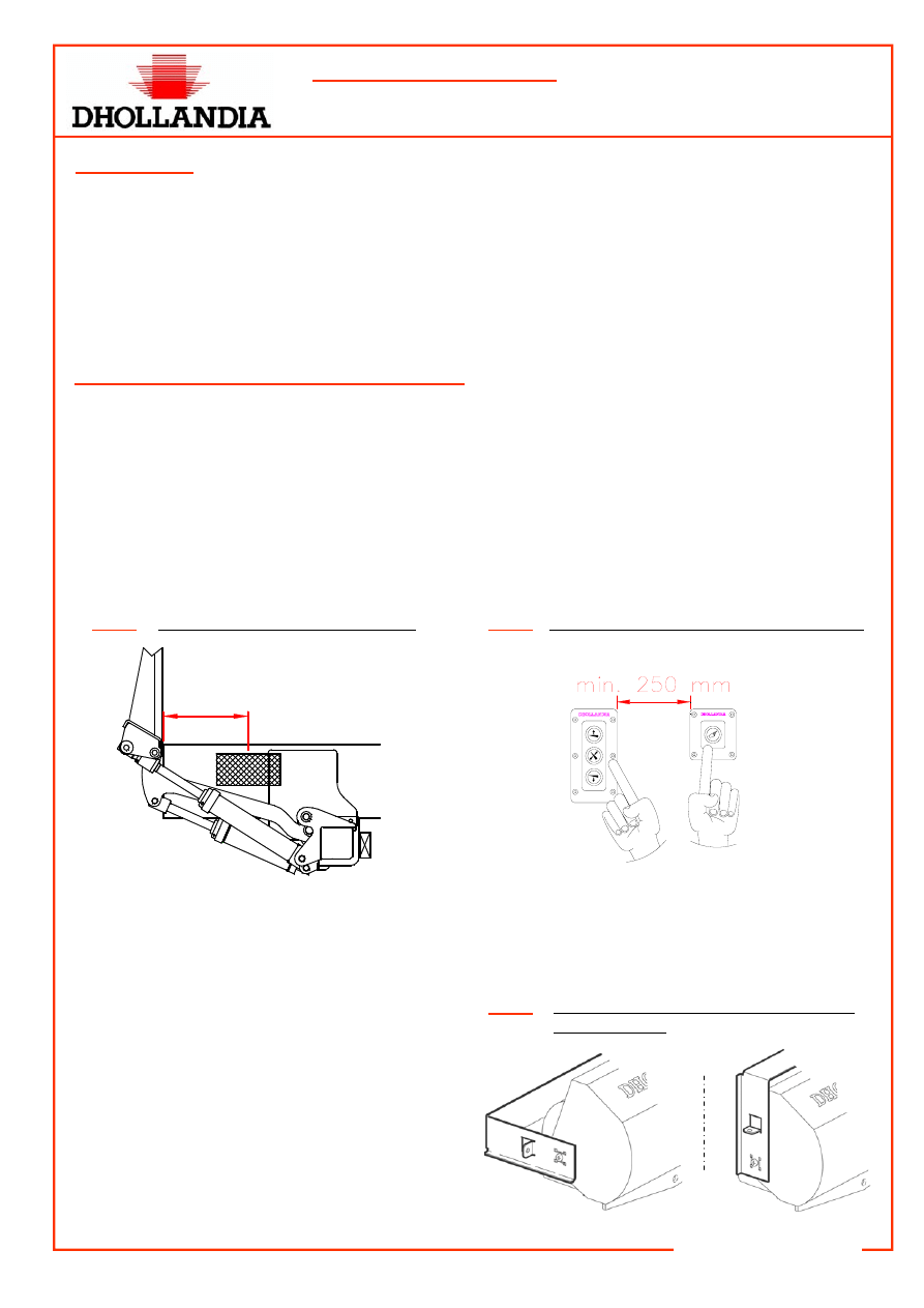
As a compromise between the 2 points, the CE safety regulations prescribe that the horizontal distance
between the rear edge of the vehicle body and the centre line of the external control box shall be:
400mm
±
100mm. See fig. 1.
•
When the 3+1 button panel controls E0179 are being used, make sure that the distance between the
main unit and the safety button is at least 250mm, in order to comply with CE safety regulations on
compulsory 2-hand operation. See fig. 2. In this case, it is recommended to mount a battery switch
E068 or equivalent near the main fuse in the battery box, or in the driver’s cabin.
400
±100 mm
Fig. 1
Safety distance for the control box
Fig. 2
Panel controls or body integrated controls
•
The steel bracket of the standard external con-
trol box can be mounted both from the top and
from the rear side of the control box. See fig. 3.
•
Attention: the mounting bracket is predrilled with
multiple holes to allow a bolt-on mounting of the
control box to the vehicle body or chassis. If you
perform a welded mounting, pay attention not to
damage the PVC control box. Preferably, dis-
connect the control box from its bracket prior to
welding.
Fig. 3
Top and side mounting of the bracket of
the control box
22/05/2006
TECHNICAL INFORMATION
Instructions for the electrical installation
Form:TEC-ELEC-01-EN
DHOLLANDIA
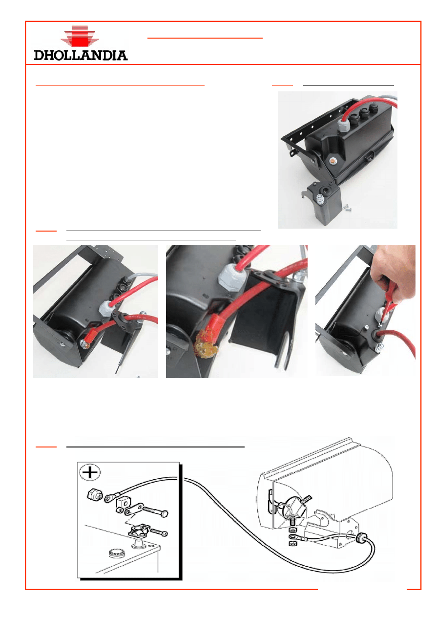
3. Fitting of the (+) power cable of the tail lift
•
From the end of 2005 onwards, the external control box is
equipped with a PVC protection hood E0355.1, under
which the connection of the 35mm² (+) power cable com-
ing from the vehicle batteries is realised. See fig. 4.
•
Lead the 35mm² (+) power cable through the seal rubber of
the protection hood E0355.1. Connect the eye of the
35mm² (+) power cable to the free pole of the battery
switch E068 acc. to fig. 5, and lock the nut tightly. Apply a
thick layer of anti-corrosive grease or Vaseline to this con-
nection, and carefully mount the PVC protection hood
E0355.1 by means of the 2 screws supplied with the con-
trol box. See fig. 5.
Fig. 4
Protection hood E0355.1
•
At the other end of the 35mm² cable, mount the 250A (or 300A) main battery fuse as close as possi-
ble to the vehicle batteries. Fit it in a location that is fully protected from adverse weather conditions.
Connect the 35mm² (+) cable coming from the control box to the main battery fuse, and link the main
fuse to the positive battery pole, either via direct mounting or via a short end of 35mm² battery cable.
Fig. 6
250A (or 300A) main fuse for installation on trucks
Fig. 5
Protective hood E0355.1 and connection of the 35mm²
(+) cable to the battery switch of the control box
22/05/2006
TECHNICAL INFORMATION
Instructions for the electrical installation
Form:TEC-ELEC-01-EN
DHOLLANDIA
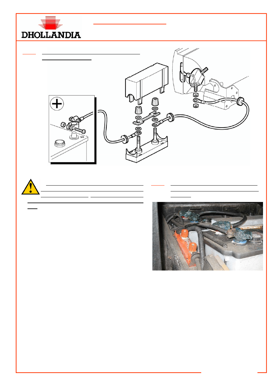
•
Lock all electric connections tightly, and
pay special attention to the locking nuts of
the fuse assemblies! Loose & insufficient fit-
ting can lead to bad contact and overheating of the
fuse, followed by premature failing of the power
circuit. Apply a thick layer of anti-corrosive
grease or Vaseline to all electric connections. See
fig. 8.
•
When fitting the 35mm³ (+) battery cable, be care-
ful to avoid rubbing, squeezing, cleaving, rupture or
other damage caused by interference with any of
the fixed or moving items of the vehicle chassis,
the body or the tail lift. Don’t’ attach the battery ca-
ble to the air or break-system conduits mounted to
the vehicle chassis. Keep the battery cable away
from the exhaust pipes of the vehicle.
Fig. 8
Lock the main fuse tightly, and apply a
thick layer of grease on all electric con-
nections.
•
In case of battery charging systems, follow the fitting instructions and electric wiring diagrams of the
vehicle manufacturer with regards to wiring and fuses.
Fig. 7
250A (or 300A) main fuse for installation on
trailers & semi-trailers
22/05/2006
TECHNICAL INFORMATION
Instructions for the electrical installation
Form:TEC-ELEC-01-EN
DHOLLANDIA
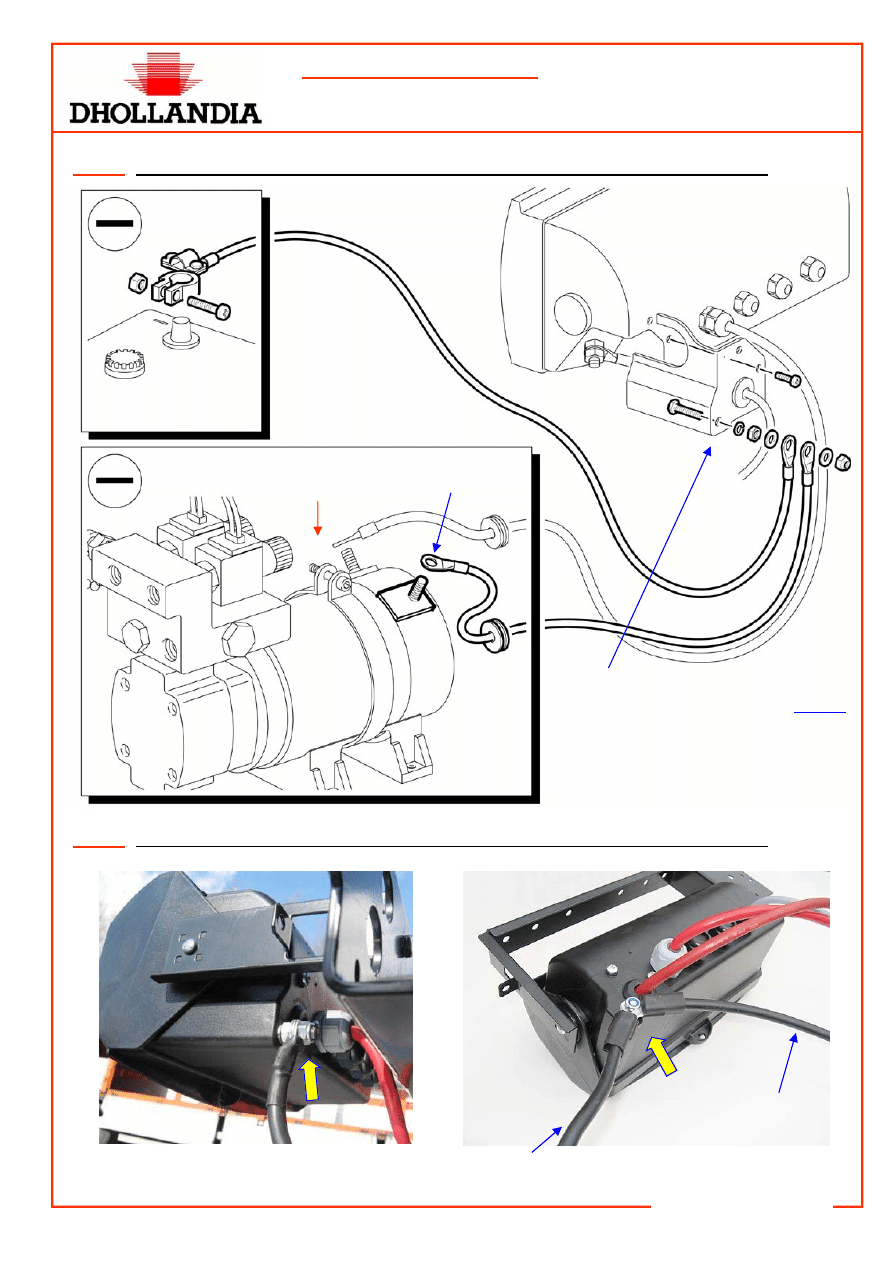
Fig. 9
Insulated earth return DIRECTLY to the negative (-) pole of the batteries.
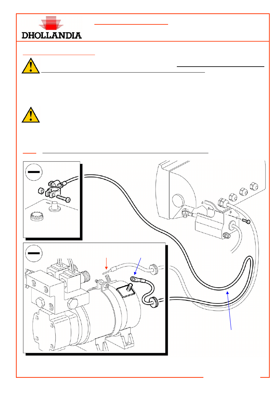
4. Fitting of the (-) earth cable
•
Besides a correct (+) power circuit (see point 3 above), a sound (-) earth circuit is equally im-
portant for the good and reliable operation of the tail lift on the long term.
•
Clearly note that the ancient (-) earth cable from the batteries to the chassis of the vehicles is left out on
a growing number of vans, trucks and tractor units. Therefore, in most cases, the tail lift fitter cannot
content himself any more with a fast and direct connection of a short length of 35 mm² to the chassis of
the vehicle!
•
In order to protect the vehicle electronics, and to avoid all kinds of problems with chassis-
mounted earth cables (bad contact due to oxidation, problems caused by insufficient removal of
the chassis paint, by vehicle vibrations, by bolt-on instead of welded tail lift mounting plates,
etc…), it is important to mount a second 35mm² cable as earth circuit between the negative (-) pole
of the electromotor of the tail lift, and the negative (-) pole of the vehicle batteries (= insulated earth
return). See fig. 9–11.
-
Blue
+
Red
Direct connection from the (–)
pole of the electromotor of the tail
lift to the (-) pole of the vehicle
batteries..
22/05/2006
TECHNICAL INFORMATION
Instructions for the electrical installation
Form:TEC-ELEC-01-EN
DHOLLANDIA
+
Red
Via the M8 earth-bolt on the protection
hood E0355.1, or even better, directly
from the (–) pole on the electromotor of
the tail lift to the (-) pole of the vehicle
batteries (see previous fig.).
(–) cable to the electromotor of
the tail lift
(–) cable to the (-)
pole of the batteries
Fig. 10
Insulated earth return via the EARTH BOLT on the rear side of the external control box
Fig. 11
Insulated earth return via the EARTH BOLT on the rear side of the external control box
-
Blue

22/05/2006
TECHNICAL INFORMATION
Instructions for the electrical installation
Form:TEC-ELEC-01-EN
DHOLLANDIA
•
During a transition period, certain types of tail lifts can still be delivered with a short length of 35 mm² (-)
earth cable on the power pack for a fast and direct earth connection to the vehicle chassis. In these
cases, it is recommended to disconnect this short length of (-) earth cable and replace it by a long 35
mm² (-) earth cable to the negative pole of the vehicle batteries; or to use this cable to connect it on the
M8 earth bolt on the protection hood E0355.1 at the rear side if the control box.
•
For the few cases where you could mount, or would prefer to mount a direct earth connection to the ve-
hicle chassis, in contrast with the instructions above, following points need to be taken into account:
1. The generalised powder coat finish of the steel components on Dhollandia lifts has a strong insulat-
ing effect, and the bolt-on instead of welded mounting of the hanging plates of the lift allows virtually
no earth connection to the chassis of the vehicle. Therefore, the minimum prevision should be a
length of 35 mm² cable from the negative (-) pole of the electromotor of the lift to the vehicle chas-
sis.
2. Prior to connecting the mounting bolt to the chassis of the vehicle, it is important that the chassis
paint is thoroughly removed from the contact surface, to enable firm contact between the cable eye
of the earth (-) cable and the naked chassis steel.
3. In any case, check and read through the technical instructions of the vehicle manufacturers to as-
sure which type of earth connection is required, possible or allowed.
5. Fitting of the electrical accessories
For the fitting of the electrical accessories (wander lead with spiral cable, foot control, fixed interior con-
trol, flashing platform lights,…), refer to the documents TEC-S090-01-NL, TEC-ELEC-02-NL, and the
electric wiring diagrams in the attachment.
Wyszukiwarka
Podobne podstrony:
Ćwiczenie 01 EN DI
Ćwiczenie 01 EN DI
wfhss training 2 01 en
wfhss workshop20071206 lecture05 01 en
Ćwiczenie 01 EN DI
Papcie(01) EN
162TEC ELEC 02 EN
vocabulary game 01 en
wfhss workshop20071206 lecture06 01 en
instrukcja obslugi do telefonu Nokia X1 01 EN
G2 4 PW EN wn Rys 01
1564283 1900SRM1107 (01 2004) UK EN
G2 4 PW EN nn um Rys 02 01
Dokumentacja systemu zarządzania jakością w oparciu o normę PN EN ISO?01 2009 (2)
01 OZE 2013 10 11 en
1470232 1900SRM0783 (01 2004) UK EN
catlist fi 01 sitransl lr260 2008 en CzujnikRadarowy
897070 2200SRM0288 (01 1994) UK EN
więcej podobnych podstron