
ð
Developer Press
Apple Computer, Inc. 1995
ð
Developer Note
Power Macintosh 7500 and
Power Macintosh 8500 Computers

ð
Apple Computer, Inc.
1995 Apple Computer, Inc.
All rights reserved.
No part of this publication may be
reproduced, stored in a retrieval
system, or transmitted, in any form or
by any means, mechanical, electronic,
photocopying, recording, or otherwise,
without prior written permission of
Apple Computer, Inc. Printed in the
United States of America.
The Apple logo is a trademark of
Apple Computer, Inc.
Use of the “keyboard” Apple logo
(Option-Shift-K) for commercial
purposes without the prior written
consent of Apple may constitute
trademark infringement and unfair
competition in violation of federal and
state laws.
No licenses, express or implied, are
granted with respect to any of the
technology described in this book.
Apple retains all intellectual property
rights associated with the technology
described in this book. This book is
intended to assist application
developers to develop applications only
for Apple Macintosh computers.
Every effort has been made to ensure
that the information in this manual is
accurate. Apple is not responsible for
printing or clerical errors.
Apple Computer, Inc.
1 Infinite Loop
Cupertino, CA 95014
408-996-1010
Apple, the Apple logo, APDA,
AppleTalk, LaserWriter, Macintosh,
Macintosh Quadra, MacTCP, PlainTalk,
and QuickTime are trademarks of
Apple Computer, Inc., registered in the
United States and other countries.
AOCE, AppleCD, AppleScript, Disk
First Aid, Finder, GeoPort, Power
Macintosh, and QuickDraw are
trademarks of Apple Computer, Inc.
Adobe Illustrator, Adobe Photoshop,
and PostScript are trademarks of Adobe
Systems Incorporated, which may be
registered in certain jurisdictions.
America Online is a registered service
mark of America Online, Inc.
CompuServe is a registered service
mark of CompuServe, Inc.
DECnet is a trademark of Digital
Equipment Corporation.
Docutek is a trademark of Xerox
Corporation.
FrameMaker is a registered trademark
of Frame Technology Corporation.
Helvetica and Palatino are registered
trademarks of Linotype Company.
Internet is a trademark of Digital
Equipment Corporation.
ITC Zapf Dingbats is a registered
trademark of International Typeface
Corporation.
NuBus is a trademark of Texas
Instruments.
Optrotech is a trademark of Orbotech
Corporation.
PowerPC is a trademark of
International Business Machines
Corporation, used under license
therefrom.
UNIX is a registered trademark of
Novell, Inc. in the United States and
other countries, licensed exclusively
through X/Open Company, Ltd.
Windows is a trademark of Microsoft
Corporation and SoftWindows is a
trademark used under license by
Insignia from Microsoft Corporation.
Simultaneously published in the United
States and Canada.
LIMITED WARRANTY ON MEDIA AND
REPLACEMENT
If you discover physical defects in the
manual or in the media on which a software
product is distributed, APDA will replace
the media or manual at no charge to you
provided you return the item to be replaced
with proof of purchase to APDA.
ALL IMPLIED WARRANTIES ON THIS
MANUAL, INCLUDING IMPLIED
WARRANTIES OF MERCHANTABILITY
AND FITNESS FOR A PARTICULAR
PURPOSE, ARE LIMITED IN DURATION
TO NINETY (90) DAYS FROM THE DATE
OF THE ORIGINAL RETAIL PURCHASE
OF THIS PRODUCT.
Even though Apple has reviewed this
manual, APPLE MAKES NO WARRANTY
OR REPRESENTATION, EITHER EXPRESS
OR IMPLIED, WITH RESPECT TO THIS
MANUAL, ITS QUALITY, ACCURACY,
MERCHANTABILITY, OR FITNESS FOR A
PARTICULAR PURPOSE. AS A RESULT,
THIS MANUAL IS SOLD “AS IS,” AND
YOU, THE PURCHASER, ARE ASSUMING
THE ENTIRE RISK AS TO ITS QUALITY
AND ACCURACY.
IN NO EVENT WILL APPLE BE LIABLE
FOR DIRECT, INDIRECT, SPECIAL,
INCIDENTAL, OR CONSEQUENTIAL
DAMAGES RESULTING FROM ANY
DEFECT OR INACCURACY IN THIS
MANUAL, even if advised of the possibility
of such damages.
THE WARRANTY AND REMEDIES SET
FORTH ABOVE ARE EXCLUSIVE AND IN
LIEU OF ALL OTHERS, ORAL OR
WRITTEN, EXPRESS OR IMPLIED. No
Apple dealer, agent, or employee is
authorized to make any modification,
extension, or addition to this warranty.
Some states do not allow the exclusion or
limitation of implied warranties or liability
for incidental or consequential damages, so
the above limitation or exclusion may not
apply to you. This warranty gives you
specific legal rights, and you may also have
other rights which vary from state to state.

iii
Contents
Figures and Tables
vii
Preface
About This Note
ix
Contents of This Note
ix
Supplemental Reference Documents
x
Apple Publications
x
Obtaining Information from APDA
x
Other Publications
xi
Conventions and Abbreviations
xii
Typographical Conventions
xii
Abbreviations
xii
Chapter 1
Introduction
1
Power Macintosh Computers at a Glance
2
Comparison With Earlier Models
2
Comparison of the New Models
4
Models and Features
6
Features of the Power Macintosh 7500
6
Features of the Power Macintosh 8500
9
Configurations
10
Compatibility
11
Open Transport
11
NuBus Expansion Cards
11
Slot Manager Compatibility
11
PowerPC 604 Compatibility Issues
12
POWER-Clean Code
12
Emulation for Compatibility
12
Code Fragments and Cache Coherency
12
Chapter 2
Architecture
13
Main Processor
14
PowerPC 601 Microprocessor
14
PowerPC 604 Microprocessor
16
Memory Subsystem
16
Read-Only Memory
16
Random-Access Memory
16
Second-Level Cache
17
Hammerhead Memory Controller IC
17

iv
Bus Bridge
17
Bandit PCI Bridge IC
18
Big-Endian and Little-Endian Bus Addressing
18
I/O Subsystem
18
Grand Central I/O Subsytem IC
18
Curio I/O Controller IC
19
Cuda Microcontroller IC
19
MESH High-Speed SCSI Interface
19
AWAC Sound IC
19
Video Subsystem
20
Video Subsystem ICs
20
Video Frame Buffer
20
Video Bus
21
Video Input
21
Second Stream Video Output
22
Chapter 3
I/O Features
23
I/O Ports
24
Serial Ports
24
Apple Desktop Bus (ADB) Port
25
Ethernet Port
26
SCSI Port
27
Sound Input Jack
28
Sound Output Jack
29
Video Monitor Connector
29
Disk Drives
31
CD-ROM Drive
31
Internal Hard Disk Drive
31
Floppy Disk Drive
32
Audio and Video Ports
33
S-Video Connectors
33
Composite Video Connectors
34
Audio Input and Output Connectors
34
Chapter 4
Expansion Features
35
RAM DIMMs
36
Installing RAM DIMMs
36
RAM DIMM Connectors
37
RAM DIMM Configurations
41
RAM Address Multiplexing
41
DRAM Devices
43
RAM Refresh
43
RAM DIMM Dimensions
43

v
Second-Level Cache SIMM
45
L2 Cache Operation
45
L2 Cache SIMM Connector
46
PCI Expansion Slots
49
DAV Connector
51
The DAV Interface
51
Signals on the DAV Connector
52
Chapter 5
Software Features
55
New Features
56
Large Volume Support
56
64-Bit Volume Addresses
56
System-Level Software
57
Application-Level Software
57
Limitations
58
Drive Setup
58
Open Transport
58
New Features of Open Transport
59
Compatibility
59
Open Firmware Startup
60
Sound & Displays Control Panel
61
Screen Icon
62
Main Window
62
Subwindows
63
Energy Saver Software
64
Performance Enhancements
66
Improved File Sharing
66
Dynamic Recompilation Emulator
66
Resource Manager in Native Code
66
Math Library
67
New BlockMove Extensions
67
Hardware Support Features
69
PCI Bus Support
69
Removal of Slot Manager Dependencies
69
PCI Compatibility
70
Setting Up a VBL Task
70
POWER-Clean Native Code
70
POWER Emulation
71
POWER-Clean Code
71
Emulation and Exception Handling
72
Code Fragments and Cache Coherency
72
Limitations of PowerPC 601 Compatibility
72
QuickDraw Acceleration API
73
Display Manager
73
Support of Native Drivers
74

vi
Chapter 6
Large Volume Support
75
Overview of the Large Volume File System
76
API Changes
76
Allocation Block Size
76
File Size Limits
77
Compatibility Requirements
77
The API Modifications
77
Data Structures
77
Extended Volume Parameter Block
77
Extended I/O Parameter Block
79
New Extended Function
81
Appendix
Abbreviations
85
Glossary
89
Index
93

vii
Figures and Tables
Chapter 1
Introduction
1
Figure 1-1
Front view of the Power Macintosh 7500 computer
6
Figure 1-2
Back view of the Power Macintosh 7500 computer
6
Figure 1-3
Unlocking the top chassis
7
Figure 1-4
Top chassis in open position
7
Figure 1-5
Front view of the Power Macintosh 8500 computer
9
Figure 1-6
Back view of the Power Macintosh 8500 computer
9
Table 1-1
Comparison of new models with earlier models
3
Table 1-2
Video input and output features
4
Table 1-3
Comparison of the new models
5
Table 1-4
Configurations
11
Chapter 2
Architecture
13
Figure 2-1
Block diagram
15
Chapter 3
I/O Features
23
Figure 3-1
Serial port connector
24
Figure 3-2
ADB connector
26
Figure 3-3
External video connector
29
Figure 3-4
A/V panel connectors on the Power Macintosh 8500
33
Figure 3-5
Seven-pin S-video connector
34
Table 3-1
Pin assignments on the serial connectors
25
Table 3-2
Pin assignments on the ADB connector
26
Table 3-3
Pin assignments on the Apple Ethernet adapter connector
27
Table 3-4
Pin assignments on the SCSI connectors
27
Table 3-5
Pin assignments on the external video connector
29
Table 3-6
Monitor sense codes
30
Table 3-7
Specifications of the AppleCD 600i CD-ROM drive
31
Table 3-8
Pin assignments on the floppy disk connector
32
Table 3-9
Pin assignments for the S-video input and output connectors
34
Chapter 4
Expansion Features
35
Figure 4-1
Dimensions of the RAM DIMM
44
Table 4-1
Pin assignments on the RAM DIMM connectors
37
Table 4-2
Signals on the RAM DIMM connector
40
Table 4-3
Memory sizes and DIMM configurations
41
Table 4-4
Address multiplexing modes for various DRAM devices
42

viii
Table 4-5
Address multiplexing
42
Table 4-6
Pin assignments on the L2 cache SIMM connector
46
Table 4-7
Signals on the L2 cache SIMM connector
49
Table 4-8
PCI signals
50
Table 4-9
Pin assignments on the DAV connector
52
Chapter 5
Software Features
55
Figure 5-1
Sound & Displays screen icon
62
Figure 5-2
Main window of the Sound & Displays control panel
63
Figure 5-3
A subwindow for a standard display monitor
63
Figure 5-4
A subwindow for an AppleVision display
64
Figure 5-5
A subwindow for sound input
64
Figure 5-6
Energy Saver control panel
65
Table 5-1
Summary of
BlockMove
routines
68

ix
P R E F A C E
About This Note
This developer note describes the Power Macintosh 7500 and Power
Macintosh 8500 computers. It compares those computers with the
earlier Power Macintosh models and emphasizes the features that are new
or different.
This developer note is intended to help hardware and software developers
design products that are compatible with the Macintosh products described in
the note. If you are not already familiar with Macintosh computers or if you
would simply like more technical information, you may wish to read the
supplementary reference documents described in this preface.
This note is published in two forms: an online version on the Apple Developer
CD Series and a paper version distributed by APDA. For information about
APDA, see “Obtaining Information from APDA” beginning on page x.
Contents of This Note
0
The information is arranged in six chapters:
■
Chapter 1, “Introduction,” gives a summary of the features of the Power
Macintosh 7500 and 8500 computers, describes their appearance, and lists
the available configurations and options.
■
Chapter 2, “Architecture,” describes the internal organization of the
computers. It includes a block diagram and descriptions of the main
components of the logic board.
■
Chapter 3, “I/O Features,” describes the built-in I/O devices and the
external I/O ports. It also describes the external video monitors that can be
used with the Power Macintosh 7500 and 8500 computers.
■
Chapter 4, “Expansion Features,” describes the expansion slots of the
Power Macintosh 7500 and 8500 computers. This chapter provides guide-
lines for designing cards for the I/O expansion slot and brief descriptions
of the expansion modules for the other slots.
■
Chapter 5, “Software Features,” summarizes the new features of the ROM
software and the system software that accompany the Power Macintosh
7500 and 8500 computers.
■
Chapter 6, “Large Volume Support,” describes the way the file system
software has been modified to support volumes larger than 4 GB.
This developer note also contains an appendix listing abbreviations, a
glossary of terms, and an index.

x
P R E F A C E
Supplemental Reference Documents
0
The following documents provide information that complements or extends
the information in this developer note.
Apple Publications
0
For information about the earlier Power Macintosh computers, refer to
Macintosh Developer Note Number 8,
APDA catalog number R0566LL/A
.
For
information about the enhanced versions of those computers, refer to
Macintosh Developer Note Number 11,
APDA catalog number R0628LL/A
.
For more information about the Macintosh implementation of the PCI bus,
including information about writing PCI drivers in native PowerPC code, see
Designing PCI Cards and Drivers for Power Macintosh Computers.
For information about the audio-video expansion features of the DAV slot,
refer to
Power Macintosh DAV Interface for PCI Expansion Cards
.
Note
Designing PCI Cards and Drivers for Power Macintosh Computers
and
Power
Macintosh DAV Interface for PCI Expansion Cards
are in preparation.
Preliminary drafts are available from Apple Developer Support.
◆
For information about the DAV interface in the first generation of Power
Macintosh computers, which used the NuBus
expansion bus, refer to
Macintosh DAV Interface for NuBus Expansion Cards,
part of
Macintosh Developer
Note Number 8.
For information about the implementations of the Apple AV technologies on
the Macintosh Quadra 840
AV
and Macintosh Centris 660
AV
computers, you
may wish to refer to
Macintosh Developer Note Number 5
.
For information about the ADB and the serial ports, you may wish to refer to
the
Guide to the Macintosh Family Hardware,
second edition.
Developers may also need copies of the appropriate Apple reference books.
You should have the relevant books of the
Inside Macintos
h series, particularly
Inside Macintosh: Devices,
Inside Macintosh: QuickTime Components,
and
Inside
Macintosh: Operating System Utilities.
Obtaining Information from APDA
0
The Apple publications listed above are available from APDA. APDA is
Apple’s worldwide source for hundreds of development tools, technical
resources, training products, and information for anyone interested in
developing applications on Apple platforms. Customers receive the
APDA

xi
P R E F A C E
Tools Catalog
featuring all current versions of Apple development tools and
the most popular third-party development tools. APDA offers convenient
payment and shipping options, including site licensing.
To order products or to request a complimentary copy of the
APDA Tools
Catalog
, contact
APDA
Apple Computer, Inc.
P.O. Box 319
Buffalo, NY 14207-0319
Other Publications
0
For information about programming the PowerPC
601 microprocessor,
developers should have copies of Motorola’s
PowerPC 601 RISC Microprocessor
User’s Manual.
Information specific to the PowerPC 604 is published in the
PowerPC 604 Microprocessor Implementation Definition Book IV.
For information about the digital video interface, refer to the
SAA7194/6
Philips Desktop Video Handbook
.
For mechanical specifications of the 8-byte DIMM, refer to the MO-161
specification of the JEDEC JC-11 committee. Electrical specifications are
defined by the JEDEC JC-42.5 committee; see JEDEC Standard No. 21-C.
For codec standards, refer to the
ASCO 2300 Audio-Stereo Codec Specification
from IT&T.
For information about the PCI expansion bus, refer to the
PCI Local Bus
Specification
, Revision 2.0, and
PCI Bus Binding to IEEE 1275-1994.
You can
obtain these documents from
PCI Special Interest Group
Intel Corporation
M/S HF3-15A
5200 NE Elam Young Parkway
Hillsboro, Oregon 97124-6497
Telephone 800-433-5177 (U.S.)
503-797-4207 (International)
Telephone
1-800-282-2732 (United States)
1-800-637-0029 (Canada)
716-871-6555 (International)
Fax
716-871-6511
AppleLink
APDA
America Online
APDAorder
CompuServe
76666,2405
Internet
APDA@applelink.apple.com

xii
P R E F A C E
For information about the Open Firmware startup process, see
1275-1994
Standard for Boot (Initialization, Configuration) Firmware,
IEEE part number
DS02683. It is referred to in this developer note as IEEE Standard 1275. You
can order a copy from
IEEE Standards Department
445 Hoes Lane, P.O. box 1331
Piscataway, NJ 08855-1331
Telephone 800-678-4333
Conventions and Abbreviations
0
This developer note uses the following conventions for typography and
abbreviations.
Typographical Conventions
0
Computer-language text—any text that is literally the same as it appears in
computer input or output—appears in
Courier
font.
Hexadecimal numbers are preceded by a dollar sign ($). For example, the
hexadecimal equivalent of decimal 16 is written as $10.
Note
A note like this contains information that is interesting but not essential
for an understanding of the text.
◆
IMPORTANT
A note like this contains important information that you should read
before proceeding.
▲
Abbreviations
0
When unusual abbreviations appear in this book, the corresponding terms
are also spelled out. Standard units of measure and other widely used
abbreviations are not spelled out. For a list of the abbreviations used in this
book, see the appendix.

C H A P T E R 1
Introduction
1
Figure 1-0
Listing 1-0
Table 1-0

C H A P T E R 1
Introduction
2
Power Macintosh Computers at a Glance
The Power Macintosh 7500 and Power Macintosh 8500 computers are new Macintosh
computers that provide greater performance and flexibility than the earlier Power
Macintosh 6100, 7100, and 8100 models. The Power Macintosh 7500 and 8500 computers
incorporate several new features, which are described in this developer note.
The Power Macintosh 7500 and 8500 computers have some of the same advanced
features as the Power Macintosh 9500 computer, described in a separate developer note.
Power Macintosh Computers at a Glance
1
This section summarizes the features of the new Power Macintosh models and compares
them with the features of the earlier models. Later chapters of this developer note
describe each feature in more detail.
Comparison With Earlier Models
1
Besides having many of the same features as the earlier models, the new Power
Macintosh models also have several new features. The most important new features are
■
a processor on a replaceable card for an easy upgrade to a more advanced
microprocessor or coprocessor
■
a memory system using 8-byte DIMMs and a 128-bit memory data bus for higher
performance
■
interfaces to I/O devices and expansion cards using the PCI expansion bus, an
industry-standard bus with higher performance than the NuBus
■
support for A/V features built into the main logic board
Table 1-1 compares the main features of the new Power Macintosh computers—
including the Power Macintosh 9500—with those of the earlier Power Macintosh models.
For features that vary within a group, the table shows the range of variation.

C H A P T E R 1
Introduction
Power Macintosh Computers at a Glance
3
*
Applies to Power Macintosh 7500 and 8500 computers only.
†
Applies to Power Macintosh 8500 computer only.
Table 1-1
Comparison of new models with earlier models
Feature
Power Macintosh 6100,
7100, and 8100 computers
Power Macintosh 7500,
8500, and 9500 computers
Processor type
PowerPC 601
PowerPC 601 or
PowerPC 604
Processor upgrade
None
By replacing processor card
Maximum size of
second-level cache
Up to 1 MB
Up to 4 MB
Type of RAM expansion
32-bit SIMM
64-bit DIMM
Maximum amount
of RAM
72–264 MB
1 GB–1.5 GB
Maximum amount
of VRAM
2 or 4 MB
4 MB
Support for 21-inch
monitors
None, 16 bpp, or 24 bpp
16 bpp or 24 bpp
Video input
Provided by A/V card
Built-in
*
Video output
Provided by A/V card
Built-in
†
DAV connector for
video processor?
Yes
Yes
*
Sound
16-bit, 44.1 MHz, stereo
input and output
Same
Internal hard disk
160 MB to 1 GB
500 MB to 2 GB
Internal drives in
addition to hard disk
and floppy disk
One 5.25-inch,
no or one 3.5-inch
One 5.25-inch,
one 3.5-inch
CD-ROM drive
Built-in on some models
Same
SCSI buses
1 fast internal,
1 external
Same
DMA for I/O devices?
Yes
Same
Network port
Ethernet (AUI)
Ethernet (AUI
and 10baseT)
GeoPort
2 serial ports
same
Number and types of
expansion slots
1–3 NuBus slots;
DAV connector in
some models
3–6 PCI slots;
DAV connector in
some models

C H A P T E R 1
Introduction
4
Power Macintosh Computers at a Glance
The video input and output capabilities of Power Macintosh 7500 and 8500 computers
extend those of the AV models in the earlier Power Macintosh computers. Table 1-2
compares the video features of the earlier models and the new models.
Note
Dual-stream video output enables the Power Macintosh 7500 and 8500
computers to display computer graphics and transmit video output at
the same time. In earlier Power Macintosh AV models, the graphics
display goes blank when the computer is transmitting video output.
◆
Comparison of the New Models
1
Table 1-3 summarizes the main features of the new Power Macintosh computers. The
Power Macintosh 9500 is included here because it has many of the same features as
the Power Macintosh 7500 and 8500.
*
Applies to Power Macintosh 8500 computer only
Table 1-2
Video input and output features
Feature
Power Macintosh 6100,
7100, and 8100 computers
Power Macintosh 7500
and 8500 computers
Video input interfaces
Composite and S-video
Composite and S-video
Video input standards
NTSC, PAL, and SECAM
NTSC, PAL, and SECAM
Color space conversions
8 bpp grayscale,
16 bpp RGB,
16 bpp YUV
8 bpp grayscale,
16 bpp RGB,
16 bpp YUV,
32 bpp RGB
Window resizing method
Decimation
Decimation
Video codec port
DAV connector
DAV connector
Clipping method
Alpha plane
Clip mask in memory
Video output interfaces
Composite and S-video
Composite and S-video
*
Video output standards
NTSC and PAL
NTSC and PAL
*
Video output convolution
With pixel depths up to
8 bpp only
With all pixel depths
Dual stream video out?
No
Yes
*
(requires
4 MB of VRAM)
Support for genlock?
No
Yes

C H A P T E R 1
Introduction
Power Macintosh Computers at a Glance
5
Table 1-3
Comparison of the new models
Feature
Power Macintosh 7500
Power Macintosh 8500
Power Macintosh 9500
Case design
Compact
Tower
Stretched Tower
Processor and clock
speed
PowerPC 601
at 100 MHz
PowerPC 604
at 100 MHz
PowerPC 604 at
120 or 132 MHz
Processor upgrade
Processor card
same
same
Size of second-level
cache
Optional,
256 KB–4 MB
256 KB; can be
expanded up to 4 MB
512 KB
Number of RAM
expansion slots
8
8
12
Minimum amount
of RAM
8 MB
16 MB
16 MB
Maximum amount
of RAM
1 GB
1 GB
1.5 GB
Amount of VRAM
2–4 MB
2–4 MB
2–4 MB (on required
PCI display card)
Pixel depth with
21-inch monitor
16 bpp (2 MB VRAM),
24 bpp (4 MB VRAM)
Same Same
Video input
Built-in, 24 bpp
Built-in, 24 bpp
None
Video output
None
Built-in
None
Sound
16-bit, 44.1 MHz,
stereo input and output
Same
Same
Internal hard disk
500 MB to 1 GB
1 GB to 2 GB
2 GB
Floppy disk
One 1.4 MB Apple
SuperDrive
Same
Same
Internal drives in
addition to hard
disk and floppy disk
One 5.25-inch,
one 3.5-inch
Same
Same
CD-ROM drive
Optional (internal,
4X speed)
Same
Same
SCSI buses
1 fast internal,
1 external
Same
Same
Network port
Ethernet (AUI and
10baseT connectors)
Same
Same
GeoPort
2 serial ports
Same
Same
Expansion slots
3 PCI slots,
1 DAV connector
3 PCI slots,
1 DAV connector
6 PCI slots
C H A P T E R 1
Introduction
6
Models and Features
Models and Features
1
This section summarizes the features of the Power Macintosh 7500 and 8500 computers.
Features of the Power Macintosh 7500
1
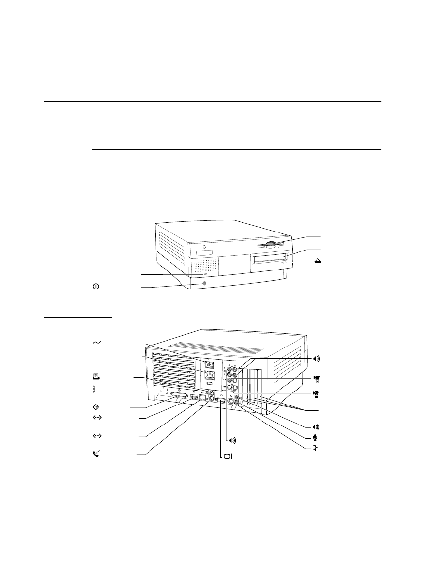
The Power Macintosh 7500 is the smallest of the new models. It has a compact
desktop case with room for expansion cards. Figure 1-2 and Figure 1-2 show front
and back views.
Figure 1-1
Front view of the Power Macintosh 7500 computer
Figure 1-2
Back view of the Power Macintosh 7500 computer
CD-ROM drive
Speaker
Floppy disk drive
Power-on light
Power button
CD-ROM drive
Open/Close button
Monitor power
socket
Monitor port
SCSI port
Ethernet port
(AUI)
Sound output port
ADB port
Sound input port
Power socket
Security lock
ports
Modem port
(GeoPort)
Printer port
Ethernet port
(10Base-T)
Composite video
input port
S-video video
input port
Audio input ports
(right and left)
Access covers for
expansion slots (3)
Audio output ports
(right and left)
C H A P T E R 1
Introduction
Models and Features
7
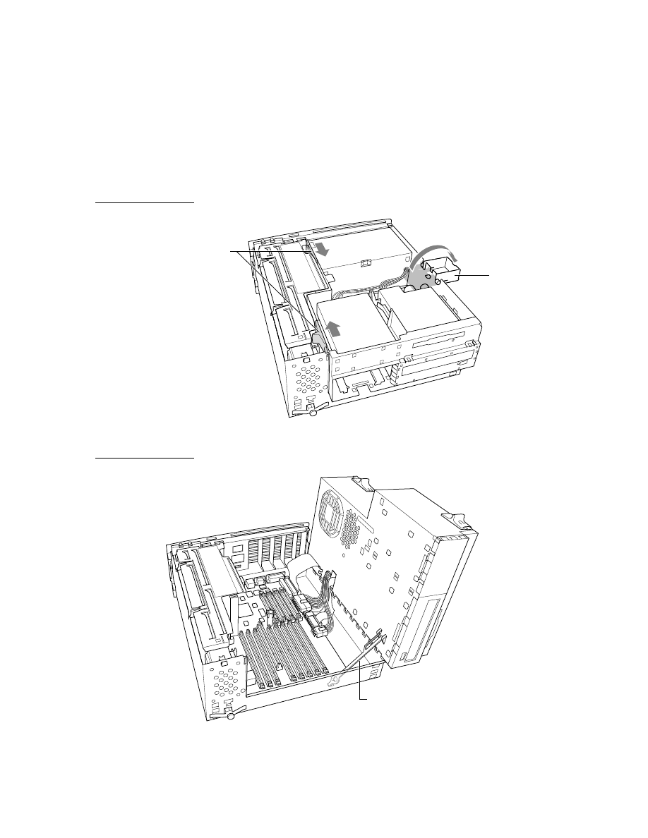
The Power Macintosh 7500 computer has a hinged top chassis that folds out of the way
to provide access to the expansion features. Figure 1-3 shows release catches and the
support foot. Figure 1-4 shows the top chassis in its open position. The support foot
shown in Figure 1-3 holds the weight of the top chassis when it is open; a stabilizing
arm, shown in Figure 1-4, keeps the top chassis in its open position.
Figure 1-3
Unlocking the top chassis
Figure 1-4
Top chassis in open position
Support foot
Release catches
Stabilizing arm

C H A P T E R 1
Introduction
8
Models and Features
The following list is a summary of the hardware features of the Power Macintosh 7500
computer. Each of these features is described later in this developer note.
■
Processor.
The Power Macintosh 7500 computer has a PowerPC
601 microprocessor
running at a clock frequency of 100 MHz.
■
Processor upgrade.
The processor subsystem is on a replaceable card for easy
upgrading to a PowerPC 604 microprocessor or coprocessor.
■
Cache SIMM.
The computer has a slot for an optional second-level cache SIMM with
256 KB to 4 MB of fast RAM.
■
RAM.
The computer has a minimum of 8 MB of main RAM.
■
RAM expansion.
The computer has eight DIMM slots for RAM expansion up to 1 GB.
■
PCI expansion.
The computer has three expansion slots that conform to PCI V2.0
specifications.
■
Video monitor support.
The built-in video interface has 2 MB of VRAM, which
provides up to 24 bpp on a 17-inch monitor and 16 bpp on a 21-inch monitor.
■
VRAM expansion.
Optional VRAM SIMMs expand VRAM to 4 MB, which provides
up to 24 bpp on a 21-inch monitor.
■
Video input capability.
The computer accepts video input for display (up to 24 bpp
and up to 640 by 480 pixels at 30 frames per second), frame capture, or QuickTime
movie capture.
■
DAV slot.
The computer has an internal DAV slot for use by an optional digital video
processor in a PCI expansion slot.
■
Standard I/O ports.
The computer has two GeoPort serial ports, an ADB port, stereo
sound input and output jacks, a SCSI port, and an Ethernet port.
■
Fast internal SCSI.
The internal SCSI bus supports transfer rates up to 10 MB/
second. (The external SCSI bus supports transfer rates up to 5 MB/second.)
■
Hard disk.
The internal hard disk has a capacity of 500 MB or 1 GB.
■
CD-ROM drive.
A built-in 4X speed CD-ROM drive is optional.
■
Space for additional drives.
The computer has space for two additional internal
drives: one 5.25-inch drive (optional CD-ROM occupies this space) and one
3.5-inch drive.
■
Floppy disk.
The computer has an internal 1.4 MB Apple SuperDrive.
C H A P T E R 1
Introduction
Models and Features
9
Features of the Power Macintosh 8500
1
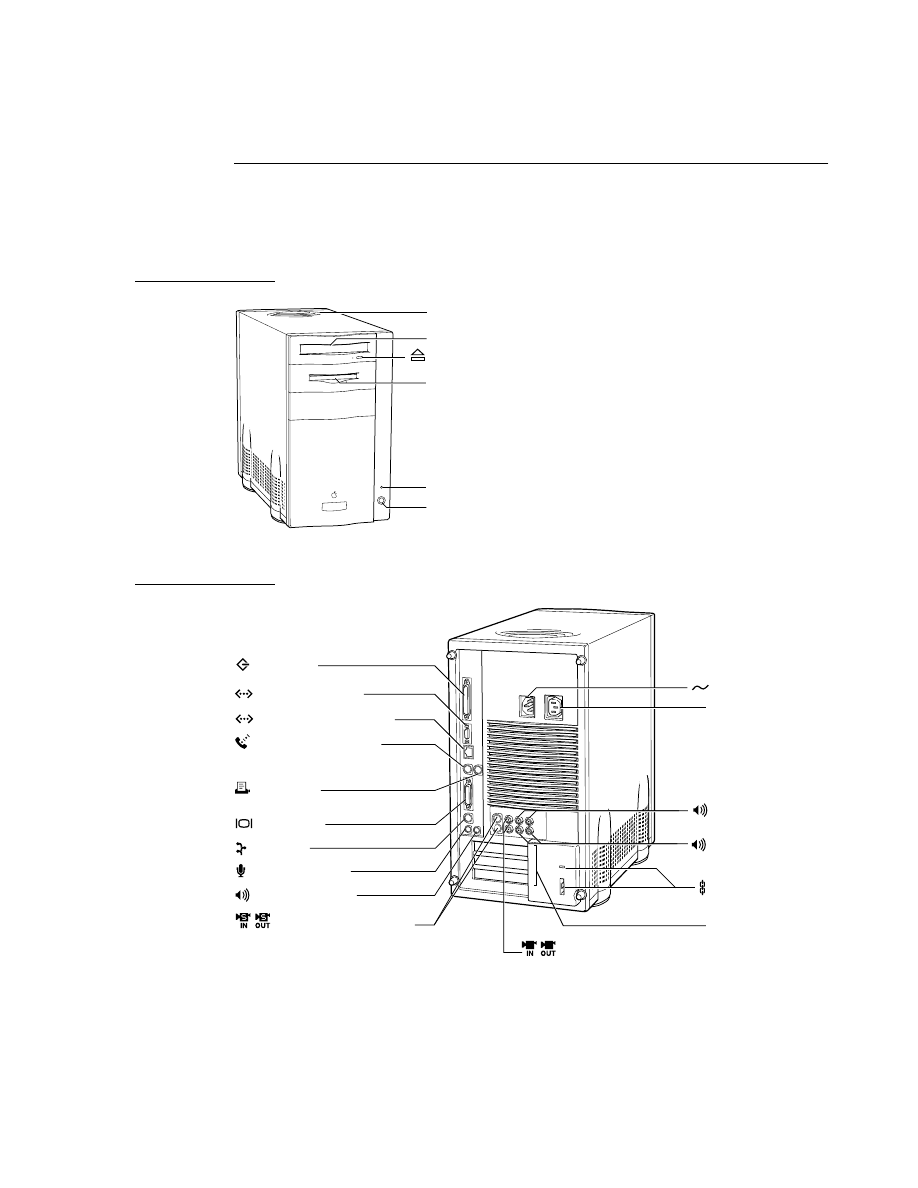
The Power Macintosh 8500 has a tower case design with room for expansion cards and
an additional internal storage device. Figure 1-5 shows a front view and Figure 1-6
shows a back view.
Figure 1-5
Front view of the Power Macintosh 8500 computer
Figure 1-6
Back view of the Power Macintosh 8500 computer
CD-ROM drive (optional)
Speaker
Floppy disk drive
Power-on light
Power button
CD-ROM drive Open/Close button
Monitor power socket
Monitor port
SCSI port
Ethernet port (AUI)
Sound output port
ADB port
Sound input port
Power socket
Security lock ports
Modem port (GeoPort)
Printer port
Ethernet port (10base-T)
S-video ports (in and out)
Composite video
ports (in and out)
Audio input ports
(left and right)
Access covers for
expansion slots (3)
Audio output ports
(left and right)

C H A P T E R 1
Introduction
10
Models and Features
The following list is a summary of the hardware features of the Power Macintosh 8500
computer. Each of these features is described later in this developer note.
■
Processor.
The Power Macintosh 8500 computer has a PowerPC 604 microprocessor
running at a clock frequency of 100 MHz.
■
Processor upgrade.
The processor subsystem is on a replaceable card for easy
upgrading to a more advanced microprocessor or coprocessor.
■
Cache SIMM.
The computer has a slot for a second-level cache SIMM with 256 KB
(or up to 4 MB) of fast RAM.
■
RAM.
The computer has a minimum of 16 MB of main RAM.
■
RAM expansion.
The computer has eight DIMM slots for RAM expansion up to 1 GB.
■
PCI expansion.
The computer has three expansion slots that conform to PCI V2.0
specifications.
■
Video monitor support.
The built-in video interface has 2 MB of VRAM, which
provides up to 16 bpp on a 21-inch monitor. VRAM is expandable to 4 MB.
■
Video input capability.
The computer accepts video input for display (up to 24 bpp
and up to 640 by 480 pixels at 30 frames per second), frame capture, or QuickTime
movie capture.
■
Video output capability.
The built-in video output can be connected to a TV monitor
or a VCR. The computer can display simultaneous graphics and video output.
■
DAV slot.
The computer has an internal DAV slot for use by an optional digital video
processor in a PCI expansion slot.
■
Standard I/O ports.
The computer has two GeoPort serial ports, an ADB port, stereo
sound input and output jacks, a SCSI port, and an Ethernet port.
■
Fast internal SCSI.
The internal SCSI bus supports transfer rates up to 10 MB/
second. (The external SCSI bus supports transfer rates up to 5 MB/second.)
■
Hard disk.
The internal hard disk has a capacity of 1 or 2 GB.
■
CD-ROM drive.
A built-in 4X speed CD-ROM drive is optional.
■
Space for additional drives.
The computer has space for three additional
internal drives: one 5.25-inch drive (optional CD-ROM occupies this space) and
two 3.5-inch drives.
■
Floppy disk.
The computer has an internal 1.4 MB Apple SuperDrive.
Configurations
1
The Power Macintosh 7500 computer is available with 8 or 16 MB of main RAM
installed. The size of the internal hard disk can be either 500 MB or 1 GB. Most
configurations also include a built-in CD-ROM drive. The Power Macintosh 8500
computer comes with 16 MB of RAM installed; the size of its internal hard disk can be
either 1 or 2 GB. Table 1-4 shows the configurations.

C H A P T E R 1
Introduction
Compatibility
11
Compatibility
1
Many features of the Power Macintosh 7500 and 8500 computers are different from those
of earlier Power Macintosh computers. This section highlights key areas you should
investigate to ensure that your hardware and software work properly with the new
computers.
Open Transport
1
To preserve compatibility with older applications, new AppleTalk and TCP/IP stacks
accept AppleTalk and TCP/IP networking calls and reroute them to the Open Transport
software. See the section “Open Transport” on page 58.
NuBus Expansion Cards
1
The Power Macintosh 7500 and 8500 computers use PCI cards for expansion and do not
have any NuBus expansion slots. For users who must be able to run NuBus expansion
cards, an external NuBus expansion chassis with two or three NuBus slots is available.
The expansion chassis has a cable that connects it to one of the computer’s PCI slots.
Slot Manager Compatibility
1
Software that uses the NuBus-specific Slot Manager to get and set information about
display cards and drivers should be updated to use the Display Manager. The Display
Manager provides a uniform API for display devices regardless of the implementation
details of the devices. For more information, see “Removal of Slot Manager
Dependencies” on page 69 and “Display Manager” on page 73.
Ordinarily, calls to the Slot Manager in the Power Macintosh 7500 and 8500 computers
return an error result; the error code depends on the specific Slot Manager routine being
called. If a NuBus expansion chassis is present and if a card occupies the specified slot,
Slot Manager calls function normally.
Table 1-4
Configurations
Model name
Amount of
DRAM
Size of internal
hard disk
Internal
CD-ROM drive?
Power Macintosh 7500
8 MB
500 MB
No
Power Macintosh 7500
8 MB
500 MB
Yes
Power Macintosh 7500
16 MB
500 MB
Yes
Power Macintosh 7500
16 MB
1 GB
Yes
Power Macintosh 8500
16 MB
1 GB
Yes
Power Macintosh 8500
16 MB
2 GB
Yes

C H A P T E R 1
Introduction
12
Compatibility
PowerPC 604 Compatibility Issues
1
The Power Macintosh 8500 computer uses the PowerPC 604 microprocessor, which is
somewhat different from the PowerPC 601 microprocessor used in the earlier Power
Macintosh models. Some of the differences can affect the compatibility of programs
developed exclusively for the PowerPC 601.
POWER-Clean Code
1
Applications for the Power Macintosh 8500 computer should be free of the POWER-only
instructions that were included in the PowerPC 601.
The instruction set of the PowerPC 601 microprocessor includes some of the same
instructions found in the instruction set of the POWER processor, and some compilers
used to generate native code for earlier Power Macintosh models generated some of
those POWER-only instructions. However, the PowerPC 604 microprocessor used in the
Power Macintosh 8500 computer does not support the POWER-only instructions. When
you compile applications for Power Macintosh computers, you should turn off the
option that allows the compiler to generate POWER-only instructions.
Emulation for Compatibility
1
The Power Macintosh 8500 computer includes software emulation of some of the
POWER features of the PowerPC 601 microprocessor. Although the term POWER
emulation is often used, a more appropriate name for this feature is PowerPC 601
compatibility. Rather than supporting the entire POWER architecture, the goal is to
support those features of the POWER architecture that are available to programs running
in user mode on the PowerPC 601–based Power Macintosh computers. For more
information, see “POWER Emulation” beginning on page 71.
Because the emulation of the POWER-only instructions degrades performance, Apple
Computer encourages developers to revise any applications that use those instructions
to conform with the PowerPC architecture. Emulation works, but performance is
degraded; POWER-clean code is better.
Code Fragments and Cache Coherency
1
Whereas the PowerPC 601 microprocessor has a single cache for both instructions and
data, the PowerPC 604 has separate instruction and data caches. As long as applications
deal with executable code by using the Code Fragment Manager, cache coherency is
maintained. Applications that bypass the Code Fragment Manager (CFM) and generate
executable code in memory, and that do not use the proper cache synchronization
instructions or CFM calls, are likely to encounter problems when running on the
PowerPC 604.

C H A P T E R 2
Architecture
2
Figure 2-0
Listing 2-0
Table 2-0

C H A P T E R 2
Architecture
14
Main Processor
This chapter describes the architecture of the Power Macintosh 7500 and Power
Macintosh 8500 computers. It describes each of the major subsystems: the main
processor, the memory subsystem, the I/O subsystem, and the video subsystem.
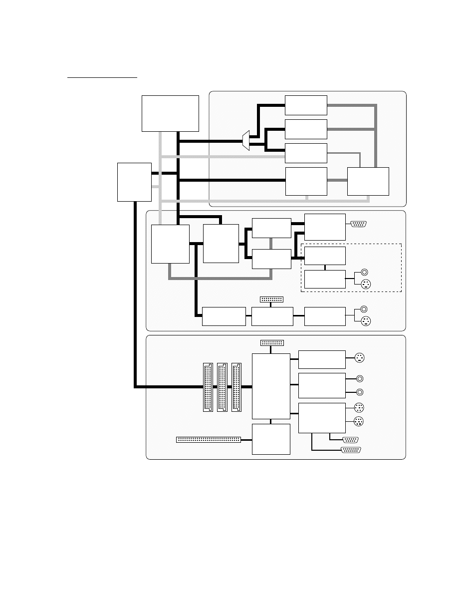
The architecture of the Power Macintosh 7500 and 8500 computers is based on three
buses: the processor bus, the PCI bus, and the video bus. The processor bus connects the
microprocessor and the memory. The PCI bus connects the expansion slots and the I/O
devices. The video bus connects the video RAM and the video input and output devices.
Figure 2-1 is a simplified block diagram of the Power Macintosh 7500 and 8500
computers showing the three buses and the major ICs on the main logic board.
Main Processor
2
The main processor and its associated clock circuits are on a plug-in card. The processor
card provides an upgrade path to a faster or more powerful microprocessor.
The main processor in the Power Macintosh 7500 computer is a PowerPC 601
microprocessor; the main processor in the Power Macintosh 8500 computer is a
PowerPC 604 microprocessor.
PowerPC 601 Microprocessor
2
The principal features of the PowerPC 601 microprocessor include
■
full RISC processing architecture
■
parallel processing units: one integer unit and one floating-point unit
■
a branch manager that can usually implement branches by reloading the incoming
instruction queue without using any processing time
■
an internal memory management unit (MMU)
■
a single built-in 32 KB cache for data and instructions
For complete technical details, see
PowerPC 601 RISC Microprocessor User’s Manual.
C H A P T E R 2
Architecture
Main Processor
15
Figure 2-1
Block diagram
MESH
fast SCSI
controller
Internal SCSI connector
Cuda
Microcontroller
AWAC
Amplifier
and codec
Curio
Ethernet, SCSI,
and SCC
Power PC 601
or Power PC 604
microprocessor
RAM SIMMs
Bank 0
ROM
Cache
SIMM
Hammerhead
Memory
controller
Bandit
PCI bus
bridge
PCI connectors
Control
Video buffer
controller
Chaos
Video
bus bridge
VRAM
expansion
VRAM
Sixty6
Convolver
7187
Video encoder
Plan B
DMA controller
8758
Video ADC
RGB video
ouput
Only on Nitro
Memory
subsystem
Video
subsystem
I/O
subsystem
RAM SIMMs
Bank 1
Grand
Central
PCI
bus
I/O system:
VIA,
SWIM III,
and I/O bus
Internal floppy disk connector
Processor
bus
ADB port
Serial ports
Sound jacks
Ethernet port
SCSI port
DAV connector
Video
output
7196
Video-decoder
Video
input
RaDACal
Video DAC

C H A P T E R 2
Architecture
16
Memory Subsystem
PowerPC 604 Microprocessor
2
The principal features of the PowerPC 604 microprocessor include
■
full RISC processing architecture
■
parallel processing units: one load-store unit, two integer units, one complex integer
unit, and one floating-point unit
■
a branch manager that can usually implement branches by reloading the incoming
instruction queue without using any processing time
■
an internal memory management unit (MMU)
■
separate built-in caches for data and instructions, 16 KB each, four-way set associative
For complete technical details, see
PowerPC 604 Microprocessor Implementation Definition
Book IV.
Memory Subsystem
2
The memory subsystem is made up of the ROM, the RAM, the second-level cache, and
the Hammerhead memory controller IC.
Read-Only Memory
2
The Power Macintosh 7500 and 8500 computers use a ROM SIMM like the one in the
earlier Power Macintosh computers. The ROM SIMM contains 4 MB of ROM with 100 ns
access time.
Random-Access Memory
2
All RAM in the Power Macintosh 7500 and 8500 computers is provided by DRAM devices
on 8-byte DIMMs (Dual Inline Memory Modules). The computers come with either 8 or
16 MB of RAM installed in the form of two DIMMs. The user can add more memory by
installing one or more additional DIMMs. When the startup software detects two DIMMs
that contain the same amount of memory, it configures their combined memory as a
single bank with a memory data bus 128 bits wide.
The Power Macintosh 7500 and 8500 computers have eight DIMM slots that can provide
1 GB of memory if fully populated with DIMMs that use 64-megabit devices. For more
information, see “RAM DIMMs” beginning on page 36.

C H A P T E R 2
Architecture
Bus Bridge
17
Second-Level Cache
2
The Power Macintosh 7500 and 8500 computers have a slot for a second-level (L2) cache
on a SIMM. The Power Macintosh 8500 computer comes with a 256 KB L2 cache SIMM
installed.
The user can install a cache SIMM by plugging the SIMM into a connector on the main
logic board. The Hammerhead memory controller IC interrogates two pins of this
connector during system startup, to determine the size of the memory on the SIMM.
If no SIMM is installed, pull-up resistors on these pins cause the Hammerhead IC
to disable all external cache operations. The Hammerhead IC is described in the
next section.
The L2 cache is organized as a write-back cache; it is direct mapped (single set) with
allocate on read or write. The cache data store is implemented with synchronous
burst static RAM devices; the cache tag store is implemented with standard static
RAM devices.
For pin assignments and mechanical specifications of the cache SIMM, see
“Second-Level Cache SIMM” beginning on page 45.
Hammerhead Memory Controller IC
2
A custom IC called Hammerhead controls the memory subsystem. The components of
the Hammerhead IC are
■
the system bus controller
■
the DRAM controller
■
the ROM controller
■
the second-level (L2) cache controller
The Hammerhead IC controls a 128-bit-wide DRAM memory array that provides
low-latency accesses and improved bandwidth. The Hammerhead IC supports main
memory sizes up to 1.5 GB. For more information about memory operation, see “RAM
Address Multiplexing” beginning on page 41.
Bus Bridge
2
As the block diagram shows, the I/O subsystem is connected to the PCI bus. The PCI
bus and the processor bus operate asynchronously: the PCI bus at a clock rate of 33 MHz
and the processor bus at 50 MHz.
Note
The video subsystem is connected to a separate bus. See “Video
Subsystem” beginning on page 20.
◆

C H A P T E R 2
Architecture
18
I/O Subsystem
Bandit PCI Bridge IC
2
The interface between the the PCI bus and the main processor and memory subsystem is
the Bandit PCI bus bridge IC. The Bandit IC provides buffering and address translation
between the processor bus and the PCI bus. The Bandit IC supports burst transfers, in
both directions, of up to 32 bytes in length—the size of a cache block.
A separate logic device (gate array) provides the priorities for bus arbitration as follows:
1. Grand Central IC (I/O device controller; highest priority)
2. PCI slots and Bandit master, in round-robin sequence: that is, each in turn, with
equal priority
The PCI expansion slots are connected directly to the PCI bus. See “PCI Expansion Slots”
beginning on page 49.
Big-Endian and Little-Endian Bus Addressing
2
The Power Macintosh 7500 and 8500 computers support both big-endian and little-
endian conventions for addressing bytes in a word. Byte order for addressing on the
processor bus is big-endian and byte order on the PCI bus is little-endian. The Bandit IC
performs the appropriate byte swapping and address transformations to translate
between the two addressing conventions. For more information about the transla-
tions between big-endian and little-endian byte order, see Part One, “The PCI Bus,”
in
Designing PCI Cards and Drivers for Power Macintosh Computers.
I/O Subsystem
2
The I/O subsystem is made up of the Grand Central IC and several I/O interface ICs, as
shown in the block diagram on page 15.
Grand Central I/O Subsytem IC
2
The Grand Central custom IC provides an interface between the standard Macintosh I/O
devices and the PCI bus. A DMA controller in the Grand Central IC supports DMA I/O
transfers through that IC’s internal I/O devices and through the Curio IC.
The Grand Central IC performs the following functions:
■
support for the Cuda IC (VIA registers)
■
central system interrupt collection
■
floppy disk interface (SWIM III)
The SWIM III floppy disk drive controller in the Grand Central IC is an extension of the
SWIM II design used in earlier Macintosh models. The SWIM III controller supports
DMA data transfers and does not require disabling of interrupts during floppy disk
accesses.

C H A P T E R 2
Architecture
I/O Subsystem
19
The Grand Central IC provides bus interfaces for the following I/O devices:
■
Curio multipurpose I/O IC
■
Cuda microcontroller IC
■
MESH controller IC for fast internal SCSI devices
■
AWAC sound amplifier and codec IC
The Grand Central IC also provides a 16-bit bus to several other devices, including the
nonvolatile RAM and the Sixty6 IC.
The Grand Central IC is connected to the PCI bus and uses the 33 MHz PCI bus clock.
Curio I/O Controller IC
2
The Curio IC is a multipurpose custom IC that contains a Media Access Controller for
Ethernet (MACE), a SCSI controller, and a Serial Communications Controller (SCC).
The SCC section of the Curio includes 8-byte FIFO buffers for both transmit and receive
data streams.
The Curio IC supports DMA transfers between its I/O ports and the computer’s
main memory.
Cuda Microcontroller IC
2
The Cuda IC is a custom version of the Motorola MC68HC05 microcontroller. It has
several functions, including
■
program control of the power supply (soft power)
■
management of system resets
■
maintenance of parameter RAM
■
control of the Apple Desktop Bus (ADB)
■
management of the real-time clock
MESH High-Speed SCSI Interface
2
The MESH IC is a custom IC that controls the SCSI bus to the internal SCSI devices.
Because this bus does not have to drive a long external bus, it can operate at higher
transfer rates than the external SCSI bus. The internal SCSI bus supports data transfers at
up to 10 MB per second; the external SCSI bus operates at up to 5 MB per second.
AWAC Sound IC
2
The audio waveform amplifier and converter (AWAC) is a custom IC that combines a
waveform amplifier with a 16-bit digital sound encoder and decoder (codec). It conforms
to the IT&T
ASCO 2300 Audio-Stereo Codec Specification
and furnishes high-quality sound

C H A P T E R 2
Architecture
20
Video Subsystem
input and output. For a description of the operation of the AWAC IC, see
Power
Macintosh DAV Interface for PCI Expansion Cards
.
A PCI expansion card can transmit digital audio to the AWAC IC by way of the DAV
connector. See the section “DAV Connector” beginning on page 51.
Video Subsystem
2
The Power Macintosh 7500 and 8500 have a built-in video subsystem that incorporates
the features of the A/V cards used with the earlier Power Macintosh computers and
adds a few enhancements. The video subsystem handles video input and output, mixes
video with computer graphics, and supports a wide variety of video monitors. In
addition, the Power Macintosh 8500 computer supports a second video output stream to
television devices such as VCRs and monitors.
The video subsystem is made up of an interface to the processor bus, 2 MB or 4 MB of
VRAM, a video stream to the computer monitor, a second video stream to the video
output, and an input video stream.
Video Subsystem ICs
2
The video subsystem is implemented by the following ICs:
■
Chaos, a custom IC that provides data bus buffering between the video subsystem
and the processor bus
■
Control, a custom IC that provides addressing and control for the video subsystem
■
RaDACal, a high-performance digital-to-analog converter (DAC) used for the video
stream to the monitor
■
Sixty6, an RGB-to-YUV converter and convolver for the second video output stream
(on the Power Macintosh 8500 computer only)
■
a 7187 digital video encoder (DENC) for the second video output stream (on the
Power Macintosh 8500 computer only)
■
an 8758 analog-to-digital converter (ADC) for the video input stream
■
a 7196 digital video decoder and scaler IC (DESC) for the video input stream
■
Plan B, a DMA controller for video input data from the 7196 DESC IC
Video Frame Buffer
2
The video frame buffer is implemented by four VRAM slots, each of which accepts a
1 MB VRAM SIMM. With two SIMMs installed (2 MB VRAM), the video display
supports up to 24 bpp on monitors up to 17 inches and 16 bpp on a 21-inch monitor.
With all four SIMMs installed (4 MB VRAM), the video display supports up to 24 bpp on
all monitors up to 21 inches.

C H A P T E R 2
Architecture
Video Subsystem
21
The data path through the video PCI to the VRAM is 64 bits wide. The output data path
from the VRAMs to the RaDACal high-performance DAC is 128 bits wide. The RaDACal
IC provides the analog R, G, and B signals to the monitor. The RaDACal IC also
generates the video timing for the monitor and supports the hardware cursor.
The Sixty6 custom IC and the 7187 DENC IC produce the second video output stream,
which can either mirror the graphics display or display a separate image.
With the full 4 MB of VRAM installed, the frame buffer can support separate
simultaneous displays on the monitor and the second video output stream. With a
second video output stream at 24 bpp, the buffer can simultaneously support up to
16 bpp on a 21-inch monitor. With a second video output stream at 16 bpp, the buffer
can support up to 24 bpp on a 21-inch monitor.
With only 2 MB of VRAM, the computer can support only one display at a time; when
the second video stream is active, the main display shuts off. With the full 4 MB of
VRAM, the graphics monitor remains active at all times.
Video Bus
2
The Control and Chaos ICs provide a separate bus bridge for the video subsystem. The
timing on the video bus is synchronous with the main system bus.
Video Input
2
The video input feature is implemented by the 8758 video ADC IC and the 7196 digital
video decoder and scaler (DESC) IC. The video data can be stored either in the video
display buffer (VRAM) or in an offscreen pixel map in main memory. Video data
transfers are DMA transfers and are controlled by a DBDMA engine in the Plan B IC.
When video input data is sent to the display buffer, it can be clipped with a 1-bit-per-pixel
clip mask using the DBDMA read channel. This mode of data transfer provides a video
play-through mode with clipping of obscured regions and menus as well as simple titles.
When video input data is stored in a pixel map in main memory, software can perform
any required clipping and blending by using the
CopyBits
routine in QuickDraw when
moving the pixel map to a visible region of the display. The video input channel
preserves the alpha channel so that software can perform alpha blending.
The Plan B IC provides two DBDMA channels for the 7196 DESC IC: a DBDMA write
channel and a DBDMA read channel. The DBDMA write channel takes data from the
pixel FIFO buffer in the 7196 IC, attaches an appropriate DMA address, and performs a
PCI write operation. The DBDMA read channel reads the 1-bit-per-pixel clip mask from
main memory.
The 7196 DESC IC can also accept video input data from the DAV connector. See the
section “DAV Connector” beginning on page 51.

C H A P T E R 2
Architecture
22
Video Subsystem
Second Stream Video Output
2
In addition to the main video display, the Power Macintosh 8500 computer provides a
second video stream for a television monitor or a VCR. The second video stream can
either duplicate the main display (mirror mode) or display an independent image. With
the full 4 MB of VRAM, the main monitor remains active while the second video stream
is active.
The second video stream is a high-quality interlaced video signal with convolution to
reduce interlace flicker. It supports television monitors using either NTSC or PAL format.
The second video stream is generated by the Sixty6 convolver IC and the 7187 video
DENC IC. The Sixty6 IC converts the video data from RGB color space to YUV color
space and then performs the convolution on the data in YUV color space. The 7187
DENC IC takes square pixels in YUV format from the Sixty6 IC and encodes them into
composite video in either NTSC or PAL format.

C H A P T E R 3
I/O Features
3
Figure 3-0
Listing 3-0
Table 3-0

C H A P T E R 3
I/O Features
24
I/O Ports
This chapter describes the I/O features of the Power Macintosh 7500 and Power
Macintosh 8500 computers, including the built-in I/O devices and the interfaces for
external I/O devices.
I/O Ports
3
The Power Macintosh 7500 and 8500 computers have the standard I/O ports found on
other Macintosh models. Figure 1-2 and Figure 1-6 in Chapter 1 show the location of the
I/O ports on the backs of the computers.
This section describes the following I/O ports:
■
serial ports
■
ADB port
■
Ethernet port
■
SCSI port
■
sound input jack
■
sound output jack
■
video monitor connector
Note
The Power Macintosh 7500 and 8500 computers also have a set of sound
and video input and output connectors grouped together on an A/V
panel. Those connectors are described in the section “Audio and Video
Ports” beginning on page 33.
◆
Serial Ports
3
The Power Macintosh 7500 and 8500 computers have two serial ports on the back panel.
Both ports use 9-pin circular mini-DIN sockets, as shown in Figure 3-1; the serial port
sockets accept either 8-pin or 9-pin plugs.
Figure 3-1
Serial port connector
8
7
1
5
4
2
3
9
6

C H A P T E R 3
I/O Features
I/O Ports
25
Either port can be independently programmed for asynchronous or synchronous
communication formats including AppleTalk and the full range of Apple GeoPort
protocols. With external adapters connected to the serial ports, the computer can
communicate with a variety of ISDN and other telephone transmission facilities.
Note
The serial ports support DMA transfers to and from main memory.
◆
Table 3-1 gives the pin assignments for both serial connectors.
Pin 9 on each serial connector provides +5 V power from the power supply for the Apple
Desktop Bus (ADB). An external device should draw no more than 100 mA from that
pin. The total current available for all devices connected to the +5 V supply for the
ADB and the serial ports is 500 mA. Excessive current drain causes a circuit breaker
to interrupt the +5 V supply; the breaker automatically resets when the load returns
to normal.
Both serial ports include the GPi (general-purpose input) signal on pin 7. The GPi signal
for each port connects to the corresponding data carrier detect input on the SCC portion
of the Curio custom IC, which is described on page 19. For more information about the
serial ports, see
Guide to the Macintosh Family Hardware,
second edition.
Apple Desktop Bus (ADB) Port
3
The Apple Desktop Bus (ADB) is an asynchronous communication bus used for
relatively slow user-input devices such as the keyboard and the mouse. The Power
Macintosh 7500 and 8500 computers have a single ADB port on the back panel. The
connector is a 4-pin mini-DIN socket, as shown in Figure 3-2.
Table 3-1
Pin assignments on the serial connectors
Pin
Name
Description
1
HSKo
Handshake output
2
HSKi
Handshake input or external clock (up to 920 Kbit/sec.)
3
TxD–
Transmit data –
4
GND
Ground
5
RxD–
Receive data –
6
TxD+
Transmit data +
7
GPi
General-purpose input (wake up CPU or perform DMA handshake)
8
RxD+
Receive data +
9
+5 V
Power to external device (500 mA maximum)

C H A P T E R 3
I/O Features
26
I/O Ports
Figure 3-2
ADB connector
The ADB is a single-master, multiple-slave serial communication bus that uses an
asynchronous protocol. The custom ADB microcontroller (the Cuda IC) drives the bus
and reads the status from the selected external device. Table 3-2 lists the ADB connector
pin assignments.
Note
The total current available for all devices connected to the +5V pins on
the ADB and the serial ports is 500 mA. Each device should use no more
than 100 mA.
◆
For more information about the ADB, see
Guide to the Macintosh Family Hardware,
second
edition. The software characteristics of the ADB are described in
Inside Macintosh: Devices.
Ethernet Port
3
The Power Macintosh 7500 and 8500 computers have a built-in Ethernet port. The
Ethernet port accepts either a 10baseT cable or the Apple Ethernet adapter for thicknet or
thinnet cables. The electrical and mechanical characteristics of the Ethernet port are the
same as on other current Macintosh computers.
The Ethernet port has two connectors but operates only one of them at a time. If devices
are plugged into both connectors, the system defaults to the 10baseT connection.
The pin assignments for the connector for the Apple Ethernet adapter are shown
in Table 3-3.
Table 3-2
Pin assignments on the ADB connector
Pin Name
Description
1
ADB
Bidirectional data bus
2
PSW
Power-on signal (generates reset and interrupt key combinations)
3
+5V
5-volt power to external device
4
GND
Ground
4
3
2
1

C H A P T E R 3
I/O Features
I/O Ports
27
SCSI Port
3
The Power Macintosh 7500 and 8500 computers have a SCSI bus for external SCSI
devices and for the internal CD-ROM drive. The external SCSI connector is a 25-pin
D-type connector; the internal CD-ROM drive uses a 50-pin connector.
Table 3-4 shows the pin assignments on the internal and external SCSI connectors.
Table 3-3
Pin assignments on the Apple Ethernet adapter connector
Pin
Name
Description
Pin
Name
Description
1
+5V
5-volt power to
external device
8
+5V
5-volt power to
external device
2
DI+
Data input +
9
DO+
Data output +
3
DI–
Data input –
10
DO–
Data output –
4
GND
Ground
11
GND
Ground
5
CI+
Control input +
12
n.c.
No connection
6
CI–
Control input –
13
n.c.
No connection
7
+5V
5-volt power to
external device
14
+5V
5-volt power to
external device
Table 3-4
Pin assignments on the SCSI connectors
Pin
(internal 50-pin
connector)
Pin
(external 25-pin
connector)
Name
Description
2
8
/DB0
Bit 0 of SCSI data bus
4
21
/DB1
Bit 1 of SCSI data bus
6
22
/DB2
Bit 2 of SCSI data bus
8
10
/DB3
Bit 3 of SCSI data bus
10
23
/DB4
Bit 4 of SCSI data bus
12
11
/DB5
Bit 5 of SCSI data bus
14
12
/DB6
Bit 6 of SCSI data bus
16
13
/DB7
Bit 7 of SCSI data bus
18
20
/DBP
Parity bit of SCSI data bus
25
–
n.c. No
connection
26
25
TPWR
+5 V terminator power
32
17
/ATN
Attention
36
6
/BSY
Bus busy
continued

C H A P T E R 3
I/O Features
28
I/O Ports
The external SCSI port has automatic termination like that on the earlier Power
Macintosh computers. When no external SCSI device is connected, the automatic
termination is active. When one or more external SCSI devices are connected, the
automatic termination is removed. As usual, the external SCSI device at the end of
the SCSI bus requires termination.
The internal end of the SCSI bus is terminated by a 110
Ω
passive terminator. The
terminator is located on the main logic board near the portion of the internal chassis
connector that contains the signals for the internal CD-ROM drive. The internal
CD-ROM drive does not include a terminator.
Sound Input Jack
3
The Power Macintosh 7500 and 8500 computers have a stereo sound input jack for
connecting an external microphone or a line-level source. The computers provide sound
digitization and recording with 16-bit samples at sample rates of up to 44.1 KHz and
support Apple Computer’s speech synthesis and recognition software.
The sound input jack is a 1/8-inch stereo phone jack with an additional contact to supply
power to an Apple microphone. The sound input jack accepts either the Apple
PlainTalk
line-level microphone or a pair of line-level signals by way of a separate adapter.
The sound input jack has the following electrical characteristics:
■
input impedance: 8000
Ω
■
maximum level: 2 V rms
■
maximum gain: 22.5 dB
■
signal-to-noise ratio: 82 dB
38
5
/ACK
Handshake acknowledge
40
4
/RST
Bus reset
42
2
/MSG
Message phase
44
19
/SEL
Select
46
15
/C/D
Control or data
48
1
/REQ
Handshake request
50
3
/I/O
Input or output
20, 22, 24, 28,
30, 34, and
all odd pins
except pin 25
7, 9, 14, 16,
18, and 24
GND
Ground
Table 3-4
Pin assignments on the SCSI connectors (continued)
Pin
(internal 50-pin
connector)
Pin
(external 25-pin
connector)
Name
Description

C H A P T E R 3
I/O Features
I/O Ports
29
Note
The Apple PlainTalk microphone requires power from the main
computer, which it obtains by way of an extra-long, 4-conductor plug
that makes contact with a 5-volt pin inside the sound input jack.
◆
Sound Output Jack
3
The Power Macintosh 7500 and 8500 computers have a stereo sound output jack for
connecting external powered speakers or other line-level devices. Inserting a plug into
the jack disconnects the internal speaker.
The sound output jack is a 1/8-inch stereo phone jack; it has the following electrical
characteristics:
■
output impedance: 37
Ω
■
maximum level: 0.9 V rms
■
maximum attenuation: 22.5 dB
■
frequency response: 20 Hz to 20 kHz, plus or minus 2 dB
■
harmonic distortion plus noise: less than 0.05 percent at 1 V rms input
■
signal to noise ratio: 85 dB; no audible discrete tones
■
channel separation: 80 dB; 32 dB when 32
Ω
headphones are connected
Video Monitor Connector
3
The Power Macintosh 7500 and 8500 computers require an external video monitor for
their graphics displays. The video monitor connector is a DB-15 connector. Figure 3-3
shows the pin numbers and Table 3-5 shows the pin assignments.
Figure 3-3
External video connector
Table 3-5
Pin assignments on the external video connector
Pin Name
Description
1
RED.GND
Red video ground
2
RED.VID
Red video signal
3
/CSYNC
Composite synchronization signal
continued
8
7
6
5
4
3
2
1
15
14
13
12
11
10
9

C H A P T E R 3
I/O Features
30
I/O Ports
To identify the type of monitor connected, the Power Macintosh 7500 and 8500
computers use the Apple monitor sense codes and the extended sense codes. Table 3-6
shows the sense codes for each of the monitors these computers can support. Refer to the
Macintosh Technical Note
M.HW.SenseLines
for a description of the sense code system.
4
SENSE0
Monitor sense signal 0
5
GRN.VID
Green video signal
6
GRN.GND
Green video ground
7
SENSE1
Monitor sense signal 1
8
n.c.
No connection
9
BLU.VID
Blue video signal
10
SENSE2
Monitor sense signal 2
11
GND
CSYNC and VSYNC ground
12
/VSYNC
Vertical synchronization signal
13
BLU.GND
Blue video ground
14
HSYNC.GND
HSYNC ground
15
/HSYNC
Horizontal synchronization signal
Shell
SGND
Shield ground
Table 3-6
Monitor sense codes
Monitor type
Standard
sense code
Extended sense code
(SENSE2–0)
(SENSE1,2)
(SENSE0,2)
(SENSE0,1)
12-inch RGB
0 1 0
—
—
—
14-inch RGB
1 1 0
—
—
—
15-inch multiple scan
1 1 0
0 0
0 0
1 1
17-inch multiple scan
1 1 0
0 0
1 0
1 1
20-inch multiple scan
1 1 0
1 0
0 0
1 1
VGA and SVGA
1 1 1
1 1
1 0
1 0
16-inch RGB
1 1 1
1 0
1 1
0 1
No monitor
1 1 1
1 1
1 1
1 1
Table 3-5
Pin assignments on the external video connector (continued)
Pin Name
Description

C H A P T E R 3
I/O Features
Disk Drives
31
Note
Both VGA and SVGA monitors have the same sense code. The first time
the user starts up with an SVGA monitor, the computer treats it as a
VGA monitor and shows a 640-by-480-pixel display. The user can switch
to the 800-by-600-pixel SVGA mode from the Monitors control panel;
when that happens, the computer changes the display to the 800-by-600-
pixel display mode immediately, and continues to use that mode the
next time it is started up.
◆
Disk Drives
3
The Power Macintosh 7500 and 8500 computers have one internal high-density
floppy disk drive and one internal hard disk drive. Some models also have an
internal CD-ROM drive.
CD-ROM Drive
3
Some configurations of the Power Macintosh 7500 and 8500 computers have a built-in
CD-ROM drive, an AppleCD 600i. The AppleCD 600i supports the worldwide standards
and specifications for CD-ROM and CD-digital audio discs described in the Sony/Philips
Yellow Book and Red Book. The drive can read CD-ROM, CD-ROM XA, CD-I, and
PhotoCD discs as well as play standard audio discs.
The AppleCD 600i CD-ROM drive has a sliding tray to hold the disc. The drive features
a quadruple-speed mechanism that supports sustained data transfer rates of 600 KB per
second and a data buffer that further enhances performance. Table 3-7 is a summary of
the specifications of the CD-ROM drive.
Internal Hard Disk Drive
3
The Power Macintosh 7500 and 8500 computers have one internal hard disk drive. The
drive capacity is either 500 MB, 1 GB or 2 GB, depending on the model.
The hard disk drive is connected to the internal SCSI bus. For pin assignments on the
internal SCSI hard disk connector, see Table 3-4 on page 27.
Table 3-7
Specifications of the AppleCD 600i CD-ROM drive
Feature
Specification
Rotation speed
Approximately 920 to 2120 rpm
Average access time
Less than 200 ms
Sustained transfer rate
600 KB per second
SCSI burst rate
More than 3 MB per second

C H A P T E R 3
I/O Features
32
Disk Drives
The internal end of the SCSI bus is terminated by a 110
Ω
passive terminator. The
terminator is located on the main logic board near the portion of the internal chassis
connector that contains the signals for the internal CD-ROM drive. The internal
CD-ROM drive does not include a terminator.
Floppy Disk Drive
3
The Power Macintosh 7500 and 8500 computers have one internal high-density floppy
disk drive (Apple SuperDrive). The drive is connected to a 20-pin connector. Table 3-8
shows the pin assignments on the floppy disk connector.
Table 3-8
Pin assignments on the floppy disk connector
Pin
Name Description
1
GND
Ground
2
PH0
Phase 0: state control line
3
GND
Ground
4
PH1
Phase 1: state control line
5
GND
Ground
6
PH2
Phase 2: state control line
7
GND
Ground
8
PH3
Phase 3: register write strobe
9
n.c.
Not connected
10
/WRREQ
Write data request
11
+5V
5-volt power to disk drive
12
SEL
Head select
13
+12V
12-volt power to disk drive
14
/ENBL
Drive enable
15
+12V
12-volt power to disk drive
16
RD
Read data
17
+12V
12-volt power to disk drive
18
WR
Write data
19
+12V
12-volt power to disk drive
20
n.c.
Not connected
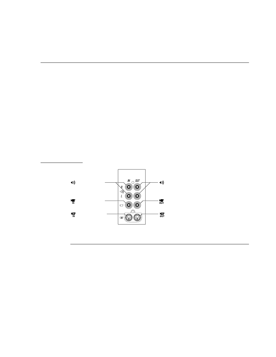
C H A P T E R 3
I/O Features
Audio and Video Ports
33
Audio and Video Ports
3
The Power Macintosh 7500 and 8500 computers have the following built-in audio and
video ports:
■
S-video input port
■
S-video output port (Power Macintosh 8500 only)
■
composite video input port
■
composite video output port (Power Macintosh 8500 only)
■
stereo sound input and output ports
The audio and video connectors are grouped together in a small A/V panel on the back
of the computer. Figure 3-4 shows the arrangement of the connectors on the A/V panel
of the Power Macintosh 8500. The A/V panel on the Power Macintosh 7500 is similar,
but it does not have the video output ports.
Figure 3-4
A/V panel connectors on the
Power Macintosh 8500
S-Video Connectors
3
The Power Macintosh 7500 and 8500 computers have S-video (Y/C) connectors for video
input and output. The video output connector is a standard 4-pin S-video connector; the
video input connector is a 7-pin connector, as shown in Figure 3-5. Table 3-9 shows the
signal assignments on the S-video connectors.
Composite video
input port
Audio input ports
(right and left)
Audio output ports
(right and left)
S-video input port
Composite video
output port
S-video output port

C H A P T E R 3
I/O Features
34
Audio and Video Ports
Figure 3-5
Seven-pin S-video connector
Composite Video Connectors
3
Composite video input and output ports are also available on RCA-type connectors.
The video input or output is connected to the center pin and the outer shell is connected
to ground.
The composite video output signal is the same as that on pin 5 of the S-video
output connector.
Audio Input and Output Connectors
3
Stereo pairs of audio input and output ports are available on RCA-type connectors.
The audio input or output is connected to the center pin and the outer shell is connected
to ground.
The audio input and output signals are the same as those described in the sections
“Sound Input Jack” on page 28 and “Sound Output Jack” on page 29.
*
Fused at 1.1 A.
Table 3-9
Pin assignments for the S-video input and output connectors
Pin
number
S-video input connector
S-video output connector
1
Analog GND
Analog GND
2
Analog GND
Analog GND
3
Video Y (luminance)
Video Y (luminance)
4
Video C (chroma)
Video C (chroma)
5
I
2
C clock (Philips serial bus)
—
6
+12 V at 250 mA maximum
*
—
7
I
2
C data (Philips serial bus)
—
1
4
7
2
5
6
3

C H A P T E R 4
Expansion Features
4
Figure 4-0
Listing 4-0
Table 4-0

C H A P T E R 4
Expansion Features
36
RAM DIMMs
This chapter describes the expansion features of the Power Macintosh 7500 and Power
Macintosh 8500 computers: the RAM expansion DIMMs, the second-level (L2) cache
SIMM, the PCI expansion slots, and the DAV connector.
RAM DIMMs
4
The Power Macintosh 7500 and 8500 computers have eight RAM expansion slots.
The RAM expansion slots accept a new type of memory module: the 8-byte DIMM
(Dual Inline Memory Module). As its name implies, the 8-byte DIMM has a 64-bit-
wide data bus.
Note
The 8-byte DIMM is also used in the Power Macintosh 9500 computer.
◆
The 8-byte DIMM is an industry standard. Its mechanical design is defined by the
MO-161 specification published by the JEDEC JC-11 committee; its electrical
characteristics are defined by the JEDEC Standard No. 21-C. The 8-byte DIMM connector
used in the Power Macintosh 7500 and 8500 computers is Burndy Corporation’s part
number ELF168E5GC-3Z50 or equivalent.
Installing RAM DIMMs
4
The 8-byte DIMMs can be installed one or more at a time. When more than one DIMM is
used, they should be installed in corresponding slot pairs. When the startup software
detects two DIMMs that are the same size and type and installed in corresponding slots,
it configures them as a single 128-bit-wide data bus for increased performance.
IMPORTANT
The Power Macintosh 7500 and 8500 computers do not have any main
memory soldered to the logic board. At least one RAM DIMM must be
present for the computer to operate.
▲
For a pair of DIMMs to function as a single 128-bit-wide pair, they must be the same type
as well as the same size. That means they must use the same addressing mode, as
defined in the section “RAM Address Multiplexing” beginning on page 41; examples are
listed in Table 4-4 on page 42.
The eight RAM expansion slots are labelled A1–A4 and B1–B4. Slots with the same
number constitute a slot pair, as follows:
Slot pair 1:
Slot A1
Slot B1
Slot pair 2:
Slot A2
Slot B2
Slot pair 3:
Slot A3
Slot B3
Slot pair 4:
Slot A4
Slot B4

C H A P T E R 4
Expansion Features
RAM DIMMs
37
RAM DIMM Connectors
4
Table 4-1 gives the pin assignments for the RAM DIMM connectors.
Table 4-1
Pin assignments on the RAM DIMM connectors
Pin
number
Signal name
Pin
number
Signal name
1
VSS
28
/CAS(0)
2
DQ(0)
29
/CAS(2)
3
DQ(1)
30
/RAS(0)
4
DQ(2)
31
/OE(0)
5
DQ(3)
32
VSS
6
VCC
33
A(0)
7
DQ(4)
34
A(2)
8
DQ(5)
35
A(4)
9
DQ(6)
36
A(6)
10
DQ(7)
37
A(8)
11
Reserved
38
A(10)
12
VSS
39
A(12)
13
DQ(8)
40
VCC
14
DQ(9)
41
Reserved
15
DQ(10)
42
Reserved
16
DQ(11)
43
VSS
17
DQ(12)
44
/OE(2)
18
VCC
45
/RAS(2)
19
DQ(13)
46
/CAS(4)
20
DQ(14)
47
/CAS(6)
21
DQ(15)
48
/WE(2)
22
Reserved
49
VCC
23
VSS
50
Reserved
24
Reserved
51
Reserved
25
Reserved
52
DQ(16)
26
VCC
53
DQ(17)
27
/WE(0)
54
VSS
continued

C H A P T E R 4
Expansion Features
38
RAM DIMMs
55
DQ(18)
85
VSS
56
DQ(19)
86
DQ(32)
57
DQ(20)
87
DQ(33)
58
DQ(21)
88
DQ(34)
59
VCC
89
DQ(35)
60
DQ(22)
90
VCC
61
Reserved
91
DQ(36)
62
Reserved
92
DQ(37)
63
Reserved
93
DQ(38)
64
Reserved
94
DQ(39)
65
DQ(23)
95
Reserved
66
Reserved
96
VSS
67
DQ(24)
97
DQ(40)
68
VSS
98
DQ(41)
69
DQ(25)
99
DQ(42)
70
DQ(26)
100
DQ(43)
71
DQ(27)
101
DQ(44)
72
DQ(28)
102
VCC
73
VCC
103
DQ(45)
74
DQ(29)
104
DQ(46)
75
DQ(30)
105
DQ(47)
76
DQ(31)
106
Reserved
77
Reserved
107
VSS
78
VSS
108
Reserved
79
PD(1)
109
Reserved
80
PD(3)
110
VCC
81
PD(5)
111
Reserved
82
PD(7)
112
/CAS(1)
83
ID(0)
113
/CAS(3)
84
VCC
114
/RAS(1)
continued
Table 4-1
Pin assignments on the RAM DIMM connectors (continued)
Pin
number
Signal name
Pin
number
Signal name

C H A P T E R 4
Expansion Features
RAM DIMMs
39
115
Reserved
142
DQ(53)
116
VSS
143
VCC
117
A(1)
144
DQ(54)
118
A(3)
145
Reserved
119
A(5)
146
Reserved
120
A(7)
147
Reserved
121
A(9)
148
Reserved
122
A(11)
149
DQ(55)
123
A(13)
150
Reserved
124
VCC
151
DQ(56)
125
Reserved
152
VSS
126
B(0)
153
DQ(57)
127
VSS
154
DQ(58)
128
Reserved
155
DQ(59)
129
/RAS(3)
156
DQ(60)
130
/CAS(5)
157
VCC
131
/CAS(7)
158
DQ(61)
132
/PDE
159
DQ(62)
133
VCC
160
DQ(63)
134
Reserved
161
Reserved
135
Reserved
162
VSS
136
DQ(48)
163
PD(2)
137
DQ(49)
164
PD(4)
138
VSS
165
PD(6)
139
DQ(50)
166
PD(8)
140
DQ(51)
167
ID(1)
141
DQ(52)
168
VCC
Table 4-1
Pin assignments on the RAM DIMM connectors (continued)
Pin
number
Signal name
Pin
number
Signal name

C H A P T E R 4
Expansion Features
40
RAM DIMMs
Table 4-8 describes the signals on the RAM DIMM connector.
B(0) is an alternate addressing signal that allows a DIMM to operate with the 64-bit data
bus split into two 32-bit halves. In the Power Macintosh 7500 and 8500 computers, A(0)
and B(0) are tied together on the main logic board.
Note
Although they are defined in JEDEC Standard No. 21-C, the presence
detect signals PD(8:1) and /PDE and the identification signals ID(1:0)
are not used in the Power Macintosh 7500 and 8500 computers.
◆
Note
No +3V power is provided on the RAM DIMM connector.
◆
Table 4-2
Signals on the RAM DIMM connector
Signal name
Description
A(13:0)
Address inputs, buffered
B(0)
Alternate version of A(0), buffered
/CAS(7:0)
Column address strobe signals, buffered
DQ(63:0)
Data input and output signals
ID(1:0)
Memory module identification (not used)
/OE(0, 2)
Output enable signals, buffered
PD(8:1)
Presence detect signals (not used)
/PDE
Presence detect enable signal (not used)
/RAS(3:0)
Row address strobe signals
Reserved
Reserved, don’t use
VCC
+5 V power
VSS
Ground
/WE(0, 2)
Read/write input signals, buffered

C H A P T E R 4
Expansion Features
RAM DIMMs
41
RAM DIMM Configurations
4
The minimum bank size supported by the Hammerhead memory controller IC is 4 MB
and the largest is 64 MB; the largest DIMM supported is a two-bank DIMM holding
128 MB. Table 4-3 shows the DIMM configurations and sizes for a range of DRAM device
sizes.
RAM Address Multiplexing
4
Depending on their internal design and size, different types of DRAM devices require
different row and column address multiplexing. The memory controller in the
Hammerhead IC supports two addressing modes, selected individually for each bank of
DRAM. The system software initializes the address mode bits in the bank base registers
as part of the process of determining the amount of RAM installed in the computer.
Signals A(11:0) on each RAM DIMM make up a 12-bit multiplexed address bus that can
support several different types of DRAM devices. Table 4-4 on page 42 shows the
address multiplexing modes used with several types of DRAM devices. The devices are
characterized by their bit dimensions: for example, a 256K by 4-bit device has 256K
addresses and stores 4 bits at a time.
Note
The memory controller does not support devices that
require more than 12 row address bits.
◆
Table 4-3
Memory sizes and DIMM configurations
DRAM
Device size
DIMM
configuration
DIMM size
Maximum memory size
with 8 DIMMs installed
4 Mbit
512 Kbits by 64
4 MB
32 MB
4 Mbit
1 Mbit by 64
8 MB
64 MB
16 Mbit
1 Mbit by 64
8 MB
64 MB
16 Mbit
2 Mbits by 64
16 MB
128 MB
16 Mbit
4 Mbits by 64
32 MB
256 MB
64 Mbit
4 Mbits by 64
32 MB
256 MB
64 Mbit
8 Mbits by 64
64 MB
512 MB
64 Mbit
16 Mbits by 64
128 MB
1 GB

C H A P T E R 4
Expansion Features
42
RAM DIMMs
Table 4-5 shows how the address signals to the RAM devices are multiplexed during the
row and column address phases.
Table 4-4
Address multiplexing modes for various DRAM devices
DRAM
device size
Device type
Size of row
address
Size of column
address
Address
mode
4 Megabits
1 M by 4 bits
10
10
1
4 Megabits
512K by 8 bits
10
9
1
4 Megabits
256K by 16 bits
10
8
0
16 Megabits
4 M by 4 bits
11
11
1
16 Megabits
4 M by 4 bits
12
10
1
16 Megabits
2 M by 8 bits
11
10
1
16 Megabits
2 M by 8 bits
12
9
0
16 Megabits
1 M by 16 bits
12
8
0
64 Megabits
16 M by 4 bits
12
12
0
64 Megabits
8 M by 8 bits
12
11
0
64 Megabits
4 M by 16 bits
11
11
1
64 Megabits
4 M by 16 bits
12
10
1
Table 4-5
Address multiplexing
Individual signals on the DRAM_ADDR bus
A(11)
A(10)
A(9)
A(8)
A(7)
A(6)
A(5)
A(4)
A(3)
A(2)
A(1)
A(0)
Address mode = 0
Row address bits
A22
A21
A20
A19
A18
A17
A16
A15
A14
A13
A12
A11
Column address bits
A26
A25
A24
A23
A10
A9
A8
A7
A6
A5
A4
A3
Address mode = 1
Row address bits
A24
A23
A21
A20
A19
A18
A17
A16
A15
A14
A13
A12
Column address bits
A25
A24
A22
A11
A10
A9
A8
A7
A6
A5
A4
A3

C H A P T E R 4
Expansion Features
RAM DIMMs
43
DRAM Devices
4
The memory controller in the Hammerhead IC supports 1 MB, 4 MB, 16 MB, and 64 MB
DRAM devices. The access time (T
RAS
) of the DRAM devices must be 70 ns or less.
IMPORTANT
The number of DRAM devices in a RAM DIMM for the Power
Macintosh 7500 and 8500 computers is constrained by the load limits of
the unbuffered signals. On each DIMM, a maximum of two devices can
be connected to each data line and a maximum of eight devices can be
connected to each /RAS line.
▲
RAM Refresh
4
The Hammerhead IC provides a CAS-before-RAS refresh cycle every 15.6
µ
s.
DRAM devices must be compatible; for example, this cycle will refresh 2K-refresh
parts within 32 ms.
RAM DIMM Dimensions
4
Figure 4-1 on page 44 shows the dimensions of the RAM DIMM.
IMPORTANT
The JEDEC MO-161 specification shows three possible heights for the
8-byte DIMM. The Power Macintosh 7500 and 8500 computers accept
only the shorter two of the three specified sizes; the maximum height is
1.255 inches.
▲
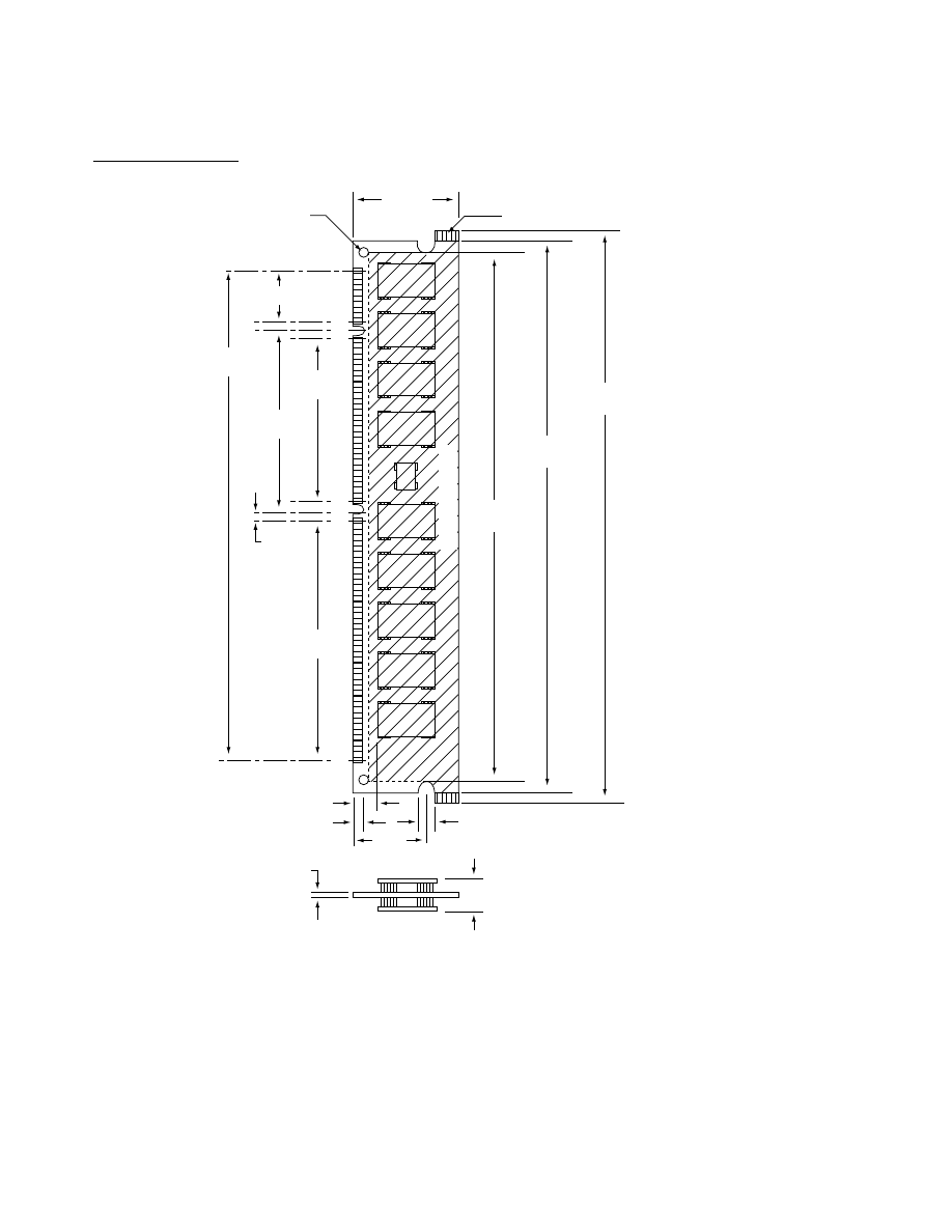
C H A P T E R 4
Expansion Features
44
RAM DIMMs
Figure 4-1
Dimensions of the RAM DIMM
+
40
41
10
11
84
+
+
Optional tabs
Optional holes
2XO 3.00
±
0.10
[0.118
±
0.004]
138.32 – 138.58
[5.445 – 5.456]
133.22 – 133.48
[5.245 – 5.255]
Component area
(127.35)
[5.01]
11.43 [0.450]
3.175
[0.125]
36.83
[1.450]
54.61
[2.150]
4.00 [0.157] minimum
4.00
±
0.10
[0.157
±
0.004]
Note: dimensions are in millimeters [inches]
9.40 [0.370] maximum
1.27
±
0.10
[0.50
±
0.004]
3.00 [0.118]
17.78
[0.700]
43.18
[1.700]
115.57
[4.550]
31.88
[1.255]
maximum
/

C H A P T E R 4
Expansion Features
Second-Level Cache SIMM
45
Second-Level Cache SIMM
4
The second-level (L2) cache in the Power Macintosh 7500 and 8500 computers occupies a
single SIMM. The size of the L2 cache SIMM can be 256 KB, 512 KB, 1 MB, or 4 MB. The
cache data store is implemented with synchronous burst static RAM devices; the cache
tag store is implemented with standard static RAM devices. The synchronous burst
SRAM devices in the cache data store must have an access time of 11 ns or less.
Note
The same L2 cache SIMM is used in both the Power Macintosh 7500 and
the Power Macintosh 8500, but with some differences in operation, as
specified in the next section.
◆
L2 Cache Operation
4
The L2 cache is organized as a write-back cache; it is direct mapped (single set) with
allocate on read or write. The L2 cache allocates on read operations from ROM addresses
and from main RAM addresses responded to by the Hammerhead memory controller.
A cache hit occurs when the contents of the tag store at the given index matches the
given address and the tag valid bit is set.
The L2 cache allocates only on burst read and write operations that miss. For nonburst
read operations that hit, the data is read from the cache. For nonburst write operations
that hit, the specified line is written back to memory before the single cycle of write data
is written back to memory.
The cache controller in the Hammerhead IC makes data available early in the timing
process by taking advantage of the following system attributes:
■
With only one processor, there is only one snooping mode so the ARTRY (address
retry) signal is never asserted for a microprocessor access that hits in the L2 cache.
■
By using the DBDIS (data bus disable) signal defined for the PowerPC 604, the cache
controller is able to assert DBG in the same cycle that TS asserts, so the processor can
accept data (DBB) in the very next cycle. The DBDIS signal allows the L2 cache RAM
devices to be enabled, driving the data bus before the direction of the access (read or
write) has been determined.
■
The DRTRY (data retry) signal is never asserted, so the controller can use non-aging
mode with the PowerPC 604.
With the PowerPC 604, data is made available, that is, the TA (transfer acknowledge)
signal is asserted, in the next clock cycle after the assertion of TS (transfer start). With the
PowerPC 601, data is made available as early as the second clock cycle after the assertion
of TS.

C H A P T E R 4
Expansion Features
46
Second-Level Cache SIMM
L2 Cache SIMM Connector
4
Table 4-1 gives the pin assignments for the L2 cache SIMM connector. The pins are listed
in the table as they appear on the connector, with pin 1 across from pin 81 and pin 80
across from pin 160.
Table 4-6
Pin assignments on the L2 cache SIMM connector
Pin
number
Signal name
Pin
number
Signal name
1
+5V
26
Gnd
2
Gnd
27
TAG(0)
3
ArDat(0)
28
TAG(2)
4
ArDat(2)
29
TAG(4)
5
ArDat(4)
30
TAG(6)
6
ArDat(6)
31
Gnd
7
Gnd
32
TAG(8)
8
ArDat(8)
33
TAG(10)
9
ArDat(10)
34
TAG(12)
10
ArDat(12)
35
TAGVALID
11
ArDat(14)
36
Gnd
12
Gnd
37
+5V
13
+5V
38
Gnd
14
Gnd
39
CacheSysClk
15
ArDat(16)
40
Gnd
16
ArDat(18)
41
TAGWEN
17
ArDat(20)
42
TAGOEN
18
ArDat(22)
43
BURSTADV
19
Gnd
44
BufAdr(12)
20
ArDat(24)
45
CacheSize(0)
21
ArDat(26)
46
BufAdr(14)
22
ArDat(28)
47
BufAdr(16)
23
ArDat(30)
48
BufAdr(18)
24
Gnd
49
BufAdr(20)
25
+5V
50
Gnd
continued

C H A P T E R 4
Expansion Features
Second-Level Cache SIMM
47
51
BufAdr(22)
81
+3.3V
52
BufAdr(24)
82
Gnd
53
BufAdr(26)
83
ArDat(1)
54
BufAdr(28)
84
ArDat(3)
55
Gnd
85
ArDat(5)
56
+5V
86
ArDat(7)
57
Gnd
87
Gnd
58
ArDat(32)
88
ArDat(9)
59
ArDat(34)
89
ArDat(11)
60
ArDat(36)
90
ArDat(13)
61
ArDat(38)
91
ArDat(15)
62
Gnd
92
Gnd
63
ArDat(40)
93
+3.3V
64
ArDat(42)
94
Gnd
65
ArDat(44)
95
ArDat(17)
66
ArDat(46)
96
ArDat(19)
67
Gnd
97
ArDat(21)
68
+5V
98
ArDat(23)
69
Gnd
99
Gnd
70
ArDat(48)
100
ArDat(25)
71
ArDat(50)
101
ArDat(27)
72
ArDat(52)
102
ArDat(29)
73
ArDat(54)
103
ArDat(31)
74
Gnd
104
Gnd
75
ArDat(56)
105
+3.3V
76
ArDat(58)
106
Gnd
77
ArDat(60)
107
TAG(1)
78
ArDat(62)
108
TAG(3)
79
Gnd
109
TAG(5)
80
+5V
110
TAG(7)
continued
Table 4-6
Pin assignments on the L2 cache SIMM connector (continued)
Pin
number
Signal name
Pin
number
Signal name

C H A P T E R 4
Expansion Features
48
Second-Level Cache SIMM
Table 4-7 describes the signals on the L2 cache SIMM connector.
111
Gnd
136
+3.3V
112
TAG(9)
137
Gnd
113
TAG(11)
138
ArDat(33)
114
TAG(13)
139
ArDat(35)
115
TAGDIRTY
140
ArDat(37)
116
Gnd
141
ArDat(39)
117
+3.3V
142
Gnd
118
BufAdr(10)
143
ArDat(41)
119
CachePrsnt
144
ArDat(43)
120
BufAdr(11)
145
ArDat(45)
121
DATAOEN
146
ArDat(47)
122
DATAWEN
147
Gnd
123
XFRSTART
148
+3.3V
124
CacheSize(1)
149
Gnd
125
Gnd
150
ArDat(49)
126
BufAdr(13)
151
ArDat(51)
127
BufAdr(15)
152
ArDat(53)
128
BufAdr(17)
153
ArDat(55)
129
BufAdr(19)
154
Gnd
130
Gnd
155
ArDat(57)
131
BufAdr(21)
156
ArDat(59)
132
BufAdr(23)
157
ArDat(61)
133
BufAdr(25)
158
ArDat(63)
134
BufAdr(27)
159
Gnd
135
Gnd
160
+3.3V
Table 4-6
Pin assignments on the L2 cache SIMM connector (continued)
Pin
number
Signal name
Pin
number
Signal name

C H A P T E R 4
Expansion Features
PCI Expansion Slots
49
PCI Expansion Slots
4
The Power Macintosh 7500 and 8500 computers have three expansion slots using
the industry standard PCI bus. The PCI bus is a nonsplit bus with 32-bit multiplexed
address and data. The PCI expansion slots in these computers use a 33 MHz
system clock.
The Power Macintosh 7500 and 8500 computers accept standard PCI cards as defined
by the
PCI Local Bus Specification
, Revision 2.0. The cards are required to use the 5 V
signaling standard and to use the standard ISA fence described in the specification.
For more information about the Macintosh implementation of the PCI bus, including
information about writing PCI drivers in native PowerPC code, see
Designing PCI Cards
and Drivers for Power Macintosh Computers.
Each computer provides a total of 50 W of power for its three expansion slots. Both 5 V
and 3.3 V are supplied; the total power at both voltages must not exceed the 50 W
maximum.
Table 4-7
Signals on the L2 cache SIMM connector
Signal name
Description
ArDat(63:0)
Processor data bus
BufAdr(27:10)
Address bus, buffered
BURSTADV
Burst advance signal to data store SRAM devices
CachePrsnt
Active (low) if an L2 cache card is installed
CacheSize(1:0)
Cache size lines: b00 for 512 KB, b01 for 256 KB,
b10 for 1 MB, b11 for 4 MB
CacheSysClk
System clock
DATAOEN
Data store output enable
DATAWEN
Data store write enable
TAG(13:0)
Tag store value
TAGDIRTY
Dirty bit from tag store
TAGOEN
Tag store output enable
TAGVALID
Valid bit from tag store
TAGWEN
Tag store write enable
XFRSTART
Transfer start signal to data store SRAM devices

C H A P T E R 4
Expansion Features
50
PCI Expansion Slots
The PCI slots support all the required PCI signals and certain optional PCI signals. The
supported PCI signals are listed in Table 4-8.
The PCI slots in the Power Macintosh 7500 and 8500 computers do not support the
following optional signals:
■
64-bit bus extension signals
■
cache support signals
■
JTAG (boundary scan) signals
■
/LOCK signal
■
error reporting signals /PERR and /SERR
Table 4-8
PCI signals
Signal name
Description
AD (31:0)
Address and data, multiplexed
C/BE(3:0)
Bus Command and Byte Enable signals, multiplexed
PAR
Parity; used with AD and C/BE signals
/FRAME
Cycle Frame; asserted to indicate a bus transaction
/TRDY
Target Ready; selected device is able to complete the current phase
/IRDY
Initiator Ready; master device is able to complete the current phase
/STOP
Stop; indicates the current target device is requesting the master to stop
the current transaction
/DEVSEL
Device Select; indicates that the driving device has decoded its address
as the target of the current access
/IDSEL
Initialization Device Select; used during configuration
/REQ
Request; indicates to the arbiter that the asserting agent requires use of
the bus
/GNT
Grant; indicates to the agent that access to the bus has been granted
CLK
Clock; rising edge provides timing for all transactions
/RST
Reset; used to bring registers and signals to a known state
/INTA,
/INTB,
/INTC,
/INTD
Interrupt request pins; wired together on each slot

C H A P T E R 4
Expansion Features
DAV Connector
51
DAV Connector
4
Audio and video signals on the main circuit board are accessible through the DAV
connector, which is located near one of the PCI expansion card connectors. A PCI
expansion card can pick up the A/V signals by means of a cable and plug for the DAV
connector. The user can install one such card in the computer.
Note
In the earlier Power Macintosh computers, part of the A/V circuitry was
on an optional plug-in card called the
AV card.
The new Power
Macintosh computers do not have an AV card; instead, all the A/V
circuitry is located on the main logic board.
◆
The DAV Interface
4
The DAV connector taps into the computer’s video and sound data streams, providing
access to the 4:2:2 unscaled digital video input signal and the digital audio input signal
for the system’s sound encoder/decoder (codec). By using the DAV interface, a PCI
expansion card can capture or generate these signals without passing them through the
PCI bus.
The DAV interface gives expansion cards greater speed and power in processing video
and sound data because cards can access data and perform PCI bus transactions
independently. For example, the DAV interface supports high-performance hardware
compression and decompression capabilities on an expansion card. A card can obtain
raw data through the DAV interface and can transfer compressed data over the PCI bus
to and from system memory or disk storage. Because the card transmits raw and
compressed data through two separate interfaces, it can achieve high processing rates.
For a complete description of the DAV slot and guidelines for developing a PCI card that
uses it, please refer to
Power Macintosh DAV Interface for PCI Expansion Cards
.
Note
The DAV interface in the earlier of Power Macintosh computers is not
the same as the one in the computers that use the PCI bus. The earlier
DAV interface is described in
Macintosh Developer Note Number 8,
listed
in “Apple Publications” on page x.
◆

C H A P T E R 4
Expansion Features
52
DAV Connector
Signals on the DAV Connector
4
The DAV connector in the Power Macintosh 7500 and 8500 computers is a 60-pin dual-
row type with 0.100-inch pin spacing. The pin assignments are shown in Table 4-9. The
pins are numbered as shown in the table, with pin 1 across from pin 31 and pin 30 across
from pin 60.
Table 4-9
Pin assignments on the DAV connector
Pin
Signal description
Pin
Signal description
1
Ground
26
Y bit 0
2
Reserved
27
Ground
3
Ground
28
Line-locked clock
4
Reserved
29
Ground
5
Ground
30
Clock reference qualifier
6
Reserved
31
Ground
7
Ground
32
Vertical sync
8
Reserved
33
Ground
9
Ground
34
Reserved
10
Reserved
35
Ground
11
UV bit 7
36
HRef
12
UV bit 6
37
Ground
13
UV bit 5
38
DIR
*
14
UV bit 4
39
IIC Data
†
15
UV bit 3
40
IIC Clock
16
UV bit 2
41
Ground
17
UV bit 1
42
Analog audio input left
18
UV bit 0
43
Analog audio input common
19
Y bit 7
44
Analog audio input right
20
Y bit 6
45
Ground
21
Y bit 5
46
Digital audio input
22
Y bit 4
47
Ground
23
Y bit 3
48
Digital audio output
24
Y bit 2
49
Ground
25
Y bit 1
50
Digital audio clock
continued

C H A P T E R 4
Expansion Features
DAV Connector
53
*
Expansion bus input, pulled down by 1 k
Ω
.
†
Inter-IC control signals, a Philips standard.
51
Ground
56
S video input Y component
52
Digital audio sync
57
Video input ground
53
Ground
58
Reserved
54
S video input C component
59
Reserved
55
Video input ground
60
Reserved
Table 4-9
Pin assignments on the DAV connector (continued)
Pin
Signal description
Pin
Signal description


C H A P T E R 5
Software Features
5
Figure 5-0
Listing 5-0
Table 5-0

C H A P T E R 5
Software Features
56
New Features
The system software for the Power Macintosh 7500 and Power Macintosh 8500
computers is based on System 7.5 and is augmented by several new features.
IMPORTANT
Even though the software for the Power Macintosh 7500 and 8500
computers incorporates significant changes from System 7.5, it is
not a reference release: that is, it is not an upgrade for earlier
Macintosh models.
▲
The system software includes changes of several kinds, including new features,
performance enhancements, and hardware support features.
New Features
5
The system software for the Power Macintosh 7500 and 8500 computers includes the
following new features:
■
large volume support
■
Drive Setup (replaces HDSC Setup)
■
transport-independent networking (Open Transport)
■
Open Firmware startup
■
Sound & Displays control panel
■
Energy Saver software
Large Volume Support
5
The largest disk volume or partition supported by System 7.5 is 4 GB. The new system
software extends that limit to 2 terabytes.
IMPORTANT
The largest possible file is still just under 2 GB.
▲
The changes necessary to support the larger volume size affect many parts of the system
software. The affected software includes system-level and application-level components.
64-Bit Volume Addresses
5
The current disk driver API has a 32-bit volume address limitation. This limitation
has been circumvented by the addition of a new 64-bit extended volume function
(
PBXGetVolInfo
) and 64-bit data types (
UnsignedWide
,
Wide
,
XVolumeParam
,
and
XIOParam
).
For the definitions of the new function and data types, please see “The API Modifications”
beginning on page 77.

C H A P T E R 5
Software Features
New Features
57
System-Level Software
5
Several system components have been modified to use the 64-bit APIs to correctly
calculate true volume sizes and read and write data to and from large disks. The
modified system components are
■
virtual memory code
■
Disk Init file
■
FSM file
■
Apple disk drivers
■
HFS ROM code
Application-Level Software
5
Current applications do not require modification to gain access to disk space beyond the
traditional 4 GB limit as long as they do not require the true size of the large partition.
Applications that need to obtain the true partition size must be modified to use the new
64-bit API and data structures. Examples of such applications are utilities for disk
formatting, partitioning, initialization, and backup.
The following application-level components of the system software have been modified
to use the 64-bit APIs:
■
Finder
■
Finder extensions (AppleScript, AOCE Mailbox, and AOCE Catalogs)
■
Drive Setup
■
Disk First Aid
In the past, the sum of the sizes of the files and folders selected in the Finder was limited
to the largest value that could be stored in a 32-bit number—that is, 4 GB. By using the
new 64-bit APIs and data structures, the Finder can now operate on selections whose
total size exceeds that limit. Even with very large volumes, the Finder can display
accurate information in folder windows and Get Info windows and obtain the true
volume size for calculating available space when copying.
The Finder extensions AppleScript, AOCE Mailbox, and AOCE Catalogs have been
modified in the same way as the Finder because their copy-engine code is similar to that
in the Finder.
The HDSC Drive Setup replacement application is described in “Drive Setup” on
page 58. The Disk First Aid application is not described in this developer note.

C H A P T E R 5
Software Features
58
New Features
Limitations
5
The software modifications that support large partition sizes do not solve all the
problems associated with the use of large volumes. In particular, the modifications do
not address the following:
■
HFS file sizes are still limited to 2 GB or less.
■
Large allocation block sizes cause inefficient storage. On a 2 GB volume, the minimum
file size is 32 KB; on a 2 terabyte volume, the minimum file size is 32 MB.
■
Drives with the new large volume device driver will not mount on computers
running older versions of the Macintosh operating system.
Drive Setup
5
The software for the Power Macintosh 7500 and 8500 computers includes a new disk
setup utility named Drive Setup. In addition to the ability to support large volumes, the
Drive Setup utility has several other enhancements over the older HDSC Setup utility,
including
■
an improved user interface
■
support for multiple partitions
■
the ability to mount volumes from applications
■
the ability to start up (boot) from any HFS partition
■
support for removable media drives
■
the ability to enable write caching for improved performance
Open Transport
5
Open Transport is the new communications and networking architecture that will
become the standard for Macintosh networking and communications. Open Transport
provides a mechanism for communications applications to operate independently from
underlying networks such as AppleTalk, TCP, or IPX. Open Transport provides a code
base and architecture that supports network stacks while eliminating many of the
interrupt latency problems associated with AppleTalk.
Note
Open Transport runs native on the PowerPC microprocessors.
◆
Open Transport has two major aspects: the client interfaces and the environment for
developing protocols and communications modules. The Open Transport client
interfaces are a superset of the XTI interface from X/Open, a consortium of UNIX
vendors. XTI is a superset of TLI, a UNIX standard interface. By using the Open
Transport interfaces, applications (called
clients
) can operate independently of the
transport layer.

C H A P T E R 5
Software Features
New Features
59
The environment for developing protocols and communications modules for Open
Transport also uses industry standards. These standards are the UNIX standard Streams,
and two other standards, Transport Provider Interface (TPI) and Data Link Provider
Interface (DLPI).
Open Transport does not use the conventional .ENET-style drivers; instead it uses
Streams-based DLPI drivers that are more appropriate for use with PCI devices. In
addition to being consistent with industry standards, Streams-based DLPI drivers
provide higher performance than .ENET-style drivers.
Apple Computer’s Open Transport software includes new stack implementations for
AppleTalk and MacTCP. Apple expects that third parties will provide implementations
of DECnet
, IPX, and other network protocols.
The Open Transport implementation of TCP/IP is a replacement for MacTCP. It is
designed for use under the Open Transport software interface.
New Features of Open Transport
5
The new features of Open Transport include
■
a new API
■
dynamic loading and shared code
■
an optional static node number (AppleTalk)
■
an optional NBP-to-catalog server (AppleTalk)
■
IP multicasting (MacTCP)
■
dynamic retransmission timers (MacTCP)
Compatibility
5
Open Transport is compatible with existing AppleTalk networks and supports existing
.ENET clients such as Soft Windows and DECnet. On the PCI-based Power Macintosh
computers, this .ENET compatibility is provided by a module that maps .ENET calls to
the corresponding DLPI calls.
Open Transport provides compatibility with 680x0-based computers by means of the
following features:
■
environment options
■
680x0-based APIs and stacks
■
Open Transport APIs and stacks
■
API compatibility glue
■
use of parameter-block APIs with Open Transport stacks for 680x0-based applications

C H A P T E R 5
Software Features
60
New Features
Open Transport provides compatibility with Power Macintosh computers by means of
the following features:
■
environment options
■
680x0-based APIs and stacks run in emulation mode
■
Open Transport APIs and stacks run in native mode
■
API compatibility glue runs in mixed mode
■
680x0-based applications can use parameter-block APIs with Open Transport stacks
■
680x0-based applications can use Open Transport APIs and stacks
■
native applications can use parameter block APIs with 680x0-based stacks
■
native applications can use parameter block APIs with Open Transport stacks
Open Firmware Startup
5
The
Open Firmware startup process
in PCI-compatible Macintosh computers conforms
to the IEEE Standard 1275 for boot firmware and the
PCI Bus Binding to IEEE 1275-1994
specification. These specifications are listed in “Supplemental Reference Documents”
beginning on page x.
The Open Firmware startup process is driven by startup firmware (also called
boot
firmware
) stored in the Macintosh ROM and in PCI card expansion ROMs. While the
startup firmware is running, the Macintosh computer starts up and configures its
hardware (including peripheral devices) independently of any operating system. The
computer then finds an operating system in ROM or on a mass storage device, loads it
into RAM, and terminates the Open Firmware startup process by giving the operating
system control of the PowerPC main processor. The operating system may be Mac OS or
some other system, provided it uses the PowerPC instruction set.
The Open Firmware startup process includes these specific features:
■
Startup firmware is written in the Forth language, as defined by the IEEE Standard
1275. Firmware code is stored in a tokenized representation called
FCode,
an
abbreviated version of Forth in which most Forth words are replaced by single bytes
or 2-byte groups. The startup firmware in the Power Macintosh ROM includes an
FCode loader that installs FCode in system RAM so that drivers can run on the
PowerPC main processor. Expansion card firmware can modify the Open Firmware
startup process by supplying FCode that the computer’s startup firmware loads and
runs before launching an operating system.
■
The startup firmware creates a data structure of nodes called a
device tree,
in which
each PCI device is described by a
property list.
The device tree is stored in system
RAM. The operating system that is ultimately installed and launched can search the
device tree to determine what devices are available.
■
Device drivers required during system startup (called
boot drivers
) are also stored in
the expansion ROM on the PCI card. Plug-in expansion cards must contain all the
driver code required during startup. The boot drivers are native drivers and are
embedded in the FCode in the expansion ROM. The startup firmware in the Power
Macintosh ROM installs the boot drivers in system RAM and lets them run on the
PowerPC main processor.

C H A P T E R 5
Software Features
New Features
61
■
The startup firmware in the Power Macintosh ROM contains debugging facilities
for both FCode and some kinds of operating-system code. These facilities can help
expansion card designers develop the firmware for new peripheral devices
compatible with Macintosh computers.
You can write PCI expansion ROM code in standard Forth words and then reduce the
result to FCode by using an
FCode tokenizer
, a program that translates Forth words into
FCodes. The Forth vocabulary that you can use is presented in IEEE Standard 1275.
The burden on developers to provide Forth boot drivers need not be heavy. Developers
can choose the level of support that they provide. The following are the three possible
levels of support:
■
No driver.
The expansion ROM contains minimal FCode. The Open Firmware startup
process recognizes the card and installs a node in the device tree, but no driver code is
loaded and no device initialization occurs.
■
Runtime driver.
Only a small amount of Forth code is required to install an
OS-dependent runtime driver in the device’s property list. Sample code is provided in
Designing PCI Cards and Drivers for Power Macintosh Computers.
■
Boot driver.
Expansion cards that need to be used at startup time must contain a boot
driver with the required methods for the type of device (typically Open, Close, Read,
and Write). Sample code is provided in
Designing PCI Cards and Drivers for Power
Macintosh Computers
.
Sound & Displays Control Panel
5
The Sound & Displays control panel is a new all-in-one control panel for the audio and
video features of Macintosh computers. The Sound & Displays control panel combines
the functions of three control panels used up until now: the Monitors and Sound control
panels found on all Macintosh models, and the Video control panel used with A/V
computers.
In addition to consolidating functions that were formerly distributed among three
different control panels, the Sound & Displays control panel provides the following
improvements:
■
gives a graphical view of the way the sound and display devices are connected
■
provides a consistent human interface for different devices and functions
■
allows configuration changes to take effect immediately
■
provides extensibility through the Control Strip
■
provides fast access to frequently used settings
■
provides user assistance through Macintosh Guide
The Sound & Displays control panel allows a user to configure the sound, video, and
display features of a Macintosh computer. By means of the Sound & Displays control
panel, the user can activate or deactivate input or output devices, determine the
arrangement of components, and adjust level settings.

C H A P T E R 5
Software Features
62
New Features
The Sound & Displays control panel is an application that resides in the Control
Panels folder. When it is installed, it overrides any Monitors or Sound control
panels already there.
Screen Icon
5
Figure 5-1 shows the Sound & Displays screen icon that appears in the Control
Panels folder.
Figure 5-1
Sound & Displays screen icon
The user can open the Sound & Displays control panel in several ways, including
■
choosing Sound & Displays from the Apple menu
■
double-clicking the Sound & Displays icon in the Control Panels folder
■
selecting the Sound & Displays icon in the Control Panels folder and choosing Open
in the Finder’s File menu
The Sound & Displays control panel consists of a main window, where the user interacts
with the A/V system as a whole, and subwindows, where the user interacts with a
particular device or category of devices.
Main Window
5
Figure 5-2 shows the main Sound & Displays window for a system with many sound
and display components. On the left is a list view of the system: lists of the devices
making up the A/V system. On the right is a map view of the A/V system: a graphical
presentation showing the sound and display components and the way they are
connected. At the bottom of the main window are the Macintosh Guide button and the
option buttons for sound and displays.
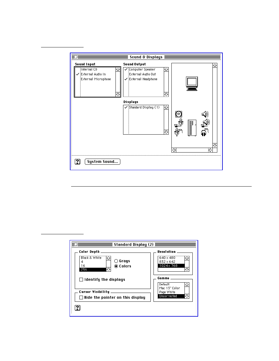
C H A P T E R 5
Software Features
New Features
63
Figure 5-2
Main window of the Sound & Displays control panel
Subwindows
5
The settings for each device are presented in individual subwindows. Figure 5-3 shows
an example of a subwindow for a standard display monitor and Figure 5-4 shows a
subwindow for an AppleVision display. Figure 5-5 shows a subwindow for sound input
settings. The features of each AV device determine the settings that appear in the
corresponding subwindow.
Figure 5-3
A subwindow for a standard display monitor
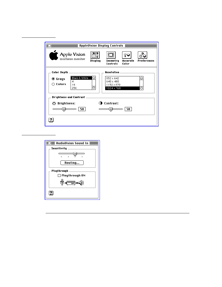
C H A P T E R 5
Software Features
64
New Features
Figure 5-4
A subwindow for an AppleVision display
Figure 5-5
A subwindow for sound input
Energy Saver Software
5
The enhanced Energy Saver software in the Power Macintosh 7500 and 8500 computers
fully exploits the Energy-Star compliant features in Macintosh computers and
peripherals, such as hard disk drives and displays. The Energy Saver software satisfies
the EPA requirements for Energy Star compliance.
The Energy Saver software is an application that resides in the Control Panels folder. The
Energy Saver control panel provides desktop computer users access to power-saving
features previously available only in portable computer power-management software.
Figure 5-6 shows the Energy Saver control panel expanded for Sleep preferences.
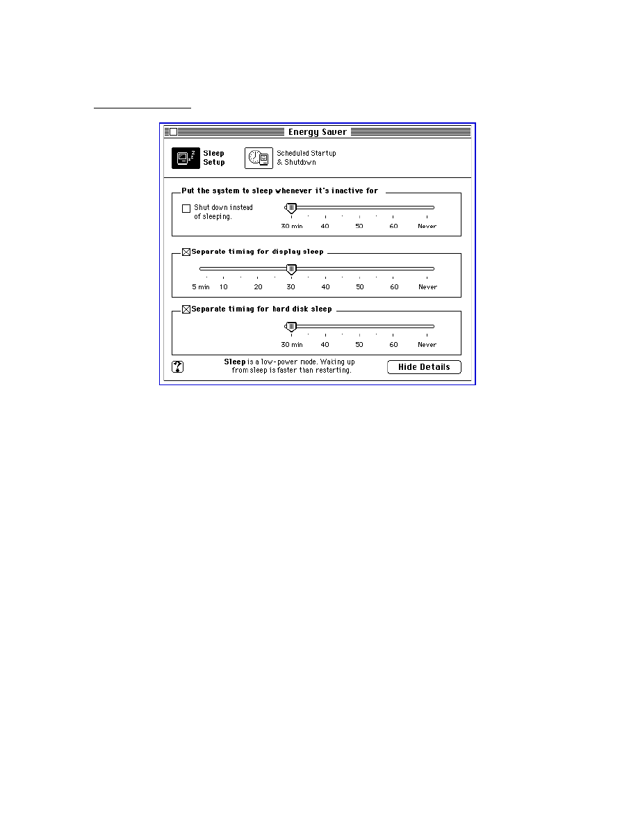
C H A P T E R 5
Software Features
New Features
65
Figure 5-6
Energy Saver control panel
The Energy Saver power management software allows the user to control the following
features:
■
Idle-time energy savings
n
computer sleep time
n
display sleep time
n
hard disk spin down time
■
Scheduled energy savings
n
scheduling of startup including bookmarking
n
scheduling of shutdown including document auto-save
■
Wakeup preferences
n
blink the power-on light when waking up
n
play a user defined sound when waking up
n
wake up when the modem detects a telephone ring
The improved single control panel interface presents a clear conceptual model of the
energy saving features of the Macintosh computer that the user can manage. It also
delivers a user experience that is as consistent as possible across desktop Macintosh
computers and portable Macintosh computers.
For more information about the Energy Saver software, see the user guide and the
Macintosh Guide help files that accompany the computer.

C H A P T E R 5
Software Features
66
Performance Enhancements
Performance Enhancements
5
The system software for the Power Macintosh 7500 and 8500 computers includes the
following performance enhancements:
■
improved file sharing
■
a new Dynamic Recompilation Emulator
■
a Resource Manager completely in native code
■
an improved math library
■
new
BlockMove
extensions
Improved File Sharing
5
Version 7.6 of the file sharing software incorporates many of the features of AppleShare,
including an API for servers.
The user can now set up shared files on ejectable media such as cartridge drives and
CD-ROM drives. The software keeps track of the status of the shared files when the
media are inserted and removed.
Dynamic Recompilation Emulator
5
The Dynamic Recompilation Emulator (or DR Emulator) is an extension to the current
interpretive emulator providing on-the-fly translation of 680x0 instructions into
PowerPC instructions for increased performance.
The design of the DR Emulator mimics a hardware instruction cache and employs a
variable size translation cache. Each compiled 680x0 instruction requires on average
about four PowerPC instructions. In operation, the DR Emulator depends on locality of
execution to make up for the extra cycles used in translating the code.
The DR Emulator provides a high degree of compatibility for 680x0 code. One area
where compatibility will be less than that of the current interpretive emulator is for
self-modifying code that does not call the cache flushing routines. Such code also has
compatibility problems on Macintosh Quadra models with the cache enabled.
Resource Manager in Native Code
5
The Resource Manager in the software for the Power Macintosh 7500 and 8500
computers is similar to the one in the earlier Power Macintosh computers except that it is
completely in native PowerPC code. Because the Resource Manager is intensively used
both by system software and by applications, the native version provides an improvement
in system performance.

C H A P T E R 5
Software Features
Performance Enhancements
67
The Process Manager has been modified to remove patches it formerly made to the
Resource Manager.
Math Library
5
The new math library (MathLib) is an enhanced version of the floating-point library
included in the ROM in the earlier Power Macintosh computers.
The new math library is bit compatible in both results and floating-point exceptions with
the math library in the earlier ROM. The only difference is in the speed of computation.
The new math library has been improved to better exploit the floating-point features of
the PowerPC microprocessor. The math library now includes enhancements that assist
the compiler in carrying out its register allocation, branch prediction, and overlapping of
integer and floating-point operations.
Compared with the previous version, the new math library provides much improved
performance without compromising its accuracy or robustness. It provides performance
gains for often-used functions of up to 15 times.
The application interface and header files for the math library have not been changed.
New BlockMove Extensions
5
The system software for the Power Macintosh 7500 and 8500 computers includes new
extensions to the
BlockMove
routine. The extensions provide improved performance for
programs running in native mode.
The new
BlockMove
extensions provide several benefits for developers.
■
They’re optimized for the PowerPC 603 and PowerPC 604 processors, rather than the
PowerPC 601.
■
They’re compatible with the new Dynamic Recompilation Emulator.
■
They provide a way to handle cache-inhibited address spaces.
■
They include new high-speed routines for setting memory to zero.
Note
The new
BlockMove
extensions do not use the string instructions,
which are fast on the PowerPC 601 but slow on other PowerPC
implementations.
◆
Some of the new
BlockMove
extensions can be called only from native code; see Table 5-1.
Except for
BlockZero
and
BlockZeroUncached
, the new
BlockMove
extensions use
the same parameters as
BlockMove
. Calls to
BlockZero
and
BlockZeroUncached
have only two parameters, a pointer and a length; refer to the header file (
Memory.h
).
Table 5-1 summarizes the
BlockMove
routines according to three criteria: whether the
routine can be called from 680x0 code, whether it is OK to use for moving 680x0 code,
and whether it is OK to use with buffers or other uncacheable destination locations.

C H A P T E R 5
Software Features
68
Performance Enhancements
The fastest way to move data is to use the
BlockMoveData
routine. It is the
recommended method whenever you are certain that the data is cacheable and
does not contain executable 680x0 code.
The
BlockMove
routine is slower than the
BlockMoveData
routine only because it has
to clear out the software cache used by the DR Emulator. If the DR EMulator is not in
use, the
BlockMove
routine and the
BlockMoveData
routine are the same.
IMPORTANT
The versions of
BlockMove
for cacheable data use the
dcbz
instruction
to avoid unnecessary pre-fetch of destination cache blocks. For
uncacheable data, you should avoid using those routines because the
dcbz
instruction causes faults on uncacheable or write-through
locations on some processors and must be emulated, making execution
extremely slow.
▲
IMPORTANT
Driver software cannot call the
BlockMove
routines directly. Instead,
drivers must use the
BlockCopy
routine, which is part of the Driver
Services Library. The
BlockCopy
routine is an abstraction that allows
you to postpone binding the specific type of
BlockMove
operation until
implementation time.
▲
The Driver Services Library is a collection of useful routines that Apple Computer
provides for developers working with the new Power Macintosh models. For more
information, please refer to Designing PCI Cards and Drivers for Power Macintosh
Computers.
*
These routines can in fact be used with non-cached buffers, but doing so severely
degrades performance on some processors.
Table 5-1
Summary of
BlockMove
routines
BlockMove
version
Can be
called from
680x0 code
OK to use
for moving
680x0 code
OK to use with
non-cached
buffers
BlockMove
Yes
Yes
No
*
BlockMoveData
Yes
No
No
*
BlockMoveDataUncached
No
No
Yes
BlockMoveUncached
No
Yes
Yes
BlockZero
No
—
No
*
BlockZeroUncached
No
—
Yes

C H A P T E R 5
Software Features
Hardware Support Features
69
Hardware Support Features
5
The system software for the Power Macintosh 7500 and 8500 computers includes the
following features to support the hardware:
■
PCI bus support
■
POWER-clean native code
■
POWER emulation (for PowerPC 601 compatibility)
■
QuickDraw acceleration API
■
Display Manager
■
support of native drivers
PCI Bus Support
5
The Power Macintosh 7500 and 8500 computers do not use NuBus
slots for hardware
expansion, but instead use the industry standard PCI bus architecture. To support these
computers as well as future Macintosh models that do not use the NuBus architecture,
new system software includes a bus-neutral expansion architecture that is used by
system software in place of Slot Manager calls that are specific to NuBus.
Removal of Slot Manager Dependencies
5
The system software that controls NuBus cards in current Macintosh models has many
explicit dependencies upon the Slot Manager. The system software for models that use
PCI bus slots requires changes to each of those dependencies so that PCI cards can
operate with the system in the same fashion as NuBus cards.
The system software that formerly called the Slot Manager has been modified to use
other services. The new Display Manager provides the means of obtaining video-specific
information that was previously obtained by way of the Slot Manager. For example,
QuickDraw currently calls the Slot Manager at startup time to check the consistency of
the
'scrn'
resource. In the software for the Power Macintosh 7500 and 8500 computers,
QuickDraw calls the new Display Manager to check this consistency.
The following components formerly used the Slot Manager; they have been modified to
use the services of the Display Manager:
■
Monitors control panel (now part of Sound & Displays control panel)
■
QuickDraw
■
Palette Manager
■
Device Manager

C H A P T E R 5
Software Features
70
Hardware Support Features
PCI Compatibility
5
To support a third-party NuBus-to-PCI expansion chassis for PCI-based computers, it is
important to retain Slot Manager capability. Also, several important applications (such as
DECnet
and SoftWindows
) rely on Slot Manager calls to indicate the presence of
networking cards. For compatibility, the new expansion architecture supports existing
PCI-based cards by way of particular Slot Manager calls.
Ordinarily, calls to the Slot Manager return an error result; the error code depends on the
specific Slot Manager routine being called. If a NuBus-to-PCI bridge is present, Slot
Manager calls function normally if a card occupies the specified slot.
To maintain compatibility with some networking software, the Power Macintosh 7500
and 8500 computers have a declaration ROM for slot 0. This declaration ROM does not
contain any drivers or other data. It is intended as an interim solution and is not to be
used by new programs.
For more information about PCI expansion cards, please refer to Designing PCI Cards and
Drivers for Power Macintosh Computers.
Setting Up a VBL Task
5
The
SlotVInstall()
and
SlotVRemove()
calls to the Vertical Retrace Manager
require a NuBus slot number as a parameter. You make such calls to set up a routine to
be executed during the vertical blanking interval of a particular video display (that is, a
slot VBL task). The Vertical Retrace Manager in the Power Macintosh 7500 and 8500
computers still supports those calls, but the slot number no longer corresponds to a
NuBus slot.
The preferred method of obtaining a slot number to use with the
SlotVInstall()
and
SlotVRemove()
routines is to look at the
dCtlSlot
field of the DCE entry for the
driver controlling the card in question. For a NuBus card, that number corresponds to
the card’s slot number. In a PCI-based machine, the
dCtlSlot
field contains a pseudo-
slot number that is assigned by the Display Manager during system startup. You can
use that number as the
theSlot
parameter in calls to the
SlotVInstall()
and
SlotVRemove()
routines. Note that the number does not correspond to the physical
location of the slot.
POWER-Clean Native Code
5
The instruction set of the PowerPC 601 microprocessor includes some of the same
instructions as those found in the instruction set of the POWER processor, and the
compiler used to generate native code for the system software in the earlier Power
Macintosh models generated some of those POWER-only instructions. However, the
PowerPC 604 microprocessor used in the Power Macintosh 8500 computer does not
support the POWER-only instructions, so a new POWER-clean version of the compiler is
being used to compile the native code fragments.

C H A P T E R 5
Software Features
Hardware Support Features
71
Note
The term POWER-clean refers to code that is free of the POWER
instructions that would prevent it from running correctly on a
PowerPC 603 or PowerPC 604 microprocessor.
◆
Here is a list of the POWER-clean native code fragments in the system software for the
Power Macintosh 8500 computer.
■
interface library
■
private interface library
■
native QuickDraw
■
MathLib
■
Mixed Mode Manager
■
Code Fragment Manager
■
Font Dispatch
■
Memory Manager
■
standard text
■
the
FMSwapFont
function
■
standard C library
POWER Emulation
5
The earlier Power Macintosh computers included emulation for certain PowerPC 601
instructions that would otherwise cause an exception. The emulation code dealt with
memory reference instructions to handle alignment and data storage exceptions. It also
handled illegal instruction exceptions caused by some PowerPC instructions that were
not implemented in the PowerPC 601. In the Power Macintosh 8500 computer, the
emulation code has been revised to include the POWER instructions that are implemented
on the PowerPC 601 but not on the PowerPC 604.
Note
Although the term POWER emulation is often used, a more appropriate
name for this feature is PowerPC 601 compatibility. Rather than
supporting the entire POWER architecture, the goal is to support those
features of the POWER architecture that are available to programs
running in user mode on the PowerPC 601–based Power Macintosh
computers.
◆
POWER-Clean Code
5
Because the emulation of the POWER-only instructions degrades performance, Apple
Computer recommends that developers revise any applications that use those
instructions to conform with the PowerPC architecture. Emulation works, but
performance is degraded; POWER-clean code is preferable.

C H A P T E R 5
Software Features
72
Hardware Support Features
Developers need to turn off POWER emulation during testing so that they can verify
that they have removed the POWER-only instructions from their applications. They can
do that by means of a control panel that is provided as part of the developers’ kit for the
PCI-based Power Macintosh computers.
Emulation and Exception Handling
5
When an exception occurs, the emulation code first checks to see whether the instruction
encoding is supported by emulation. If it is not, the code passes the original cause of
the exception (illegal instruction or privileged instruction) to the application as a
native exception.
If the instruction is supported by emulation, the code then checks a flag bit to see
whether emulation has been enabled. If emulation is not enabled at the time, the
emulator generates an illegal instruction exception.
Code Fragments and Cache Coherency
5
Whereas the PowerPC 601 microprocessor has a single cache for both instructions and
data, the PowerPC 604 has separate instruction and data caches. As long as applications
deal with executable code by using the Code Fragment Manager (CFM), cache coherency
is maintained. Applications that bypass the Code Fragment Manager and generate
executable code in memory, and that do not use the proper cache synchronization
instructions or CFM calls, are likely to encounter problems when running on the
PowerPC 604.
IMPORTANT
The emulation software in the Power Macintosh 8500 computer cannot
make the separate caches in the PowerPC 604 behave like the combined
cache in the PowerPC 601. Applications that generate executable code in
memory must be modified to use the Code Fragment Manager or
maintain proper cache synchronization by other means.
▲
Limitations of PowerPC 601 Compatibility
5
The emulation code in the Power Macintosh 8500 computer allows programs compiled
for the PowerPC 601 to execute without halting on an exception whenever they use a
POWER-only feature. For most of those features, the emulation matches the results that
are obtained on a Power Macintosh computer with a PowerPC 601. However, there are a
few cases where the emulation is not an exact match; those cases are summarized here.
■
MQ register.
Emulation does not match the undefined state of this register after
multiply and divide instructions.
■
div
and
divo
instructions.
Emulation does not match undefined results after
an overflow.
■
Real-time clock registers.
Emulation matches the 0.27 percent speed discrepancy of
the Power Macintosh models that use the PowerPC 601 microprocessor, but the values
of the low-order 7 bits are not 0.

C H A P T E R 5
Software Features
Hardware Support Features
73
■
POWER version of
dec
register.
Emulation includes the POWER version, but
decrementing at a rate determined by the time-base clock, not by the real-time clock.
■
Cache line compute size (
clcs
) instruction.
Emulation returns values appropriate
for the type of PowerPC microprocessor.
■
Undefined special-purpose register (SPR) encodings.
Emulation does not ignore
special-purpose register encodings higher than 32.
■
Invalid forms.
Invalid combinations of register operands with certain instructions
may produce results that do not match those of the PowerPC 601.
■
Floating-point status and control register (FPSCR).
The FPSCR in the PowerPC 601
does not fully conform to the PowerPC architecture, but the newer PowerPC
processors do.
QuickDraw Acceleration API
5
The native QuickDraw acceleration API makes it easier for third-party card vendors and
driver writers to produce video accelerator cards for the Power Macintosh 7500 and 8500
computers.
The QuickDraw acceleration API is the current accelerator interface for the PowerPC
version of native QuickDraw. It allows a patch chaining mechanism for decisions on
categories of block transfers, and also specifies the format and transport of the data to
the accelerator.
IMPORTANT
The interface and design of the QuickDraw acceleration API is intended
only for the PCI-based Power Macintosh computers; it does not
represent a new standard for all Macintosh models.
▲
Display Manager
5
Until now, system software has used the NuBus-specific Slot Manager to get and set
information about display cards and drivers. New system software removes this explicit
software dependency on the architecture of the expansion bus. The Display Manager
provides a uniform API for display devices regardless of the implementation details of
the devices.
In a computer that uses PCI expansion cards, the Slot Manager is generally not available
to provide information about display cards; instead, the Name Registry must be used.
The Display Manager makes the actual calls to either the Slot Manager or the Name
Registry, as appropriate, thus isolating the bus-specific calls to a single component and
avoiding the need to change additional system software in the future. See the section
“Removal of Slot Manager Dependencies” on page 69.

C H A P T E R 5
Software Features
74
Hardware Support Features
Support of Native Drivers
5
The Power Macintosh 7500 and 8500 computers use a new native-driver model for
system software and device driver developers. Several components of system software
are being modified to support native drivers. The modified components are
■
Device Manager
■
interrupt tree services
■
driver loader library
■
driver support library
■
Slot Manager stubs
■
Macintosh startup code
■
interface libraries
■
system registry
For more information about device drivers and the native-driver model, refer to
Designing PCI Cards and Drivers for Power Macintosh Computers.

C H A P T E R 6
Large Volume Support
6
Figure 6-0
Listing 6-0
Table 6-0

C H A P T E R 6
Large Volume Support
76
Overview of the Large Volume File System
This chapter describes the large volume file system for the Power Macintosh 7500 and
Power Macintosh 8500 computers. The large volume file system is a version of the
hierarchical file system (HFS) that has been modified to support volume sizes larger than
the previous 4 GB limit.
Overview of the Large Volume File System
6
The large volume file system includes
■
modifications to the HFS ROM code, Disk First Aid, and Disk Init
■
a new extended API that allows reporting of volume size information beyond the
previous 4 GB limit
■
new device drivers and changes to the Device Manager API to support devices that
are greater than 4 GB
■
a new version of Drive Setup that supports large volumes and chainable drivers
(needed to boot large volumes on earlier Macintosh models)
API Changes
6
The system software on the Power Macintosh 7500 and 8500 computers allows all
current applications to work without modifications. Unmodified applications that call
the file system still receive incorrect values for large volume sizes. The Finder and other
utility programs that need to know the actual size of a volume have been modified to use
the new extended
PBXGetVolInfo
function to obtain the correct value.
The existing low-level driver interface does not support I/O to a device with a range of
addresses greater than 4 GB because the positioning offset (in bytes) for a read or write
operation is a 32-bit value. To correct this problem, a new extended I/O parameter block
record has been defined. This extended parameter block has a 64-bit positioning offset.
The new parameter block and the extended
PBXGetVolInfo
function are described in
“The API Modifications” beginning on page 77.
Allocation Block Size
6
The format of HFS volumes has not changed. What has changed is the way the HFS
software handles the allocation block size. Existing HFS code treats the allocation block
as a 16-bit integer. The large volume file system uses the full 32 bits of the allocation
block size parameter. In addition, any software that deals directly with the allocation
block size from the volume control block must now treat it as a true 32-bit value.
Even for the larger volume sizes, the number of allocation blocks is still defined by a
16-bit integer. As the volume size increases, the size of the allocation block also increases.
For a 2 GB volume, the allocation block size is 32 KB and therefore the smallest file on
that disk will occupy at least 32 KB of disk space.

C H A P T E R 6
Large Volume Support
The API Modifications
77
The maximum number of files will continue to be less than 65,000. This limit is directly
related to the fixed number of allocation blocks.
File Size Limits
6
The HFS has a maximum file size of 2 GB. The large volume file system does not remove
that limit because doing so would require a more extensive change to the current API
and would incur more compatibility problems.
Compatibility Requirements
6
The large volume file system requires at least a 68020 microprocessor or a Power
Macintosh model that emulates it. In addition, the file system requires a Macintosh IIci
or more recent model. On a computer that does not meet both those requirements, the
large volume file system driver will not load.
The large volume file system requires System 7.5 or later and a new Finder that supports
volumes larger than 4 GB (using the new extended
PBXGetVolInfo
function).
The API Modifications
6
The HFS API has been modified to support volume sizes larger than 4 GB. The
modifications consist of two extended data structures and a new extended
PBXGetVolInfo
function.
Data Structures
6
This section describes the two modified data structures used by the large volume
file system:
■
the extended volume parameter block
■
the extended I/O parameter block
Extended Volume Parameter Block
6
In the current
HVolumeParam
record, volume size information is clipped at 2 GB.
Because HFS volumes can now exceed 4 GB, a new extended volume parameter block
is needed in order to report the larger size information. The
XVolumeParam
record
contains 64-bit integers for reporting the total bytes on the volume and the number
of free bytes available (field names
ioVTotalBytes
and
ioVFreeBytes
). In addition,
several of the fields that were previously signed are now unsigned (field names
ioVAtrb
,
ioVBitMap
,
ioAllocPtr
,
ioVAlBlkSiz
,
ioVClpSiz
,
ioAlBlSt
,
ioVNxtCNID
,
ioVWrCnt
,
ioVFilCnt
, and
ioVDirCnt
).

C H A P T E R 6
Large Volume Support
78
The API Modifications
struct XVolumeParam {
ParamBlockHeader
ProcPtr
ioCompletion
// pointer to completion routine
OSErr
ioResult
// result code
StringPtr
ioNamePtr
// pointer to volume name
short
ioVRefNum
// volume specification
unsigned long
ioXVersion;
// XVolumeParam version == 0
short
ioVolIndex;
// volume index
unsigned long
ioVCrDate;
// date & time of creation
unsigned long
ioVLsMod;
// date & time of last modification
unsigned short
ioVAtrb;
// volume attributes
unsigned short
ioVNmFls;
// number of files in root directory
unsigned short
ioVBitMap;
// first block of volume bitmap
unsigned short
ioAllocPtr;
// first block of next new file
unsigned short
ioVNmAlBlks;
// number of allocation blocks
unsigned long
ioVAlBlkSiz;
// size of allocation blocks
unsigned long
ioVClpSiz;
// default clump size
unsigned short
ioAlBlSt;
// first block in volume map
unsigned long
ioVNxtCNID;
// next unused node ID
unsigned short
ioVFrBlk;
// number of free allocation blocks
unsigned short
ioVSigWord;
// volume signature
short
ioVDrvInfo;
// drive number
short
ioVDRefNum;
// driver reference number
short
ioVFSID;
// file-system identifier
unsigned long
ioVBkUp;
// date & time of last backup
unsigned short
ioVSeqNum;
// used internally
unsigned long
ioVWrCnt;
// volume write count
unsigned long
ioVFilCnt;
// number of files on volume
unsigned long
ioVDirCnt;
// number of directories on volume
long
ioVFndrInfo[8];
// information used by the Finder
uint64
ioVTotalBytes;
// total number of bytes on volume
uint64
ioVFreeBytes;
// number of free bytes on volume
};
Field descriptions
ioCompletion
The pointer to the completion routine.
ioResult
The result code of the function.
ioNamePtr
The pointer to the name of the volume.
ioVRefNum
On input, the volume specification;
on output, the volume reference number.
ioXVersion
The version number of
XVolumeParam
; defined as 0.
ioVolIndex
An index for use with the
PBXGetVInfo
function.
ioVCrDate
The date and time of volume initialization.

C H A P T E R 6
Large Volume Support
The API Modifications
79
ioVLsMod
The date and time the volume information was last modified. (This
field is not changed when information is written to a file and does
not necessarily indicate when the volume was flushed.)
ioVAtrb
The volume attributes.
ioVNmFls
The number of files in the root directory.
ioVBitMap
The first block of the volume bitmap.
ioAllocPtr
The block at which the next new file starts. Used internally.
ioVNmAlBlks
The number of allocation blocks.
ioVAlBlkSiz
The size of allocation blocks.
ioVClpSiz
The default clump size.
ioAlBlSt
The first block in the volume map.
ioVNxtCNID
The next unused catalog node ID.
ioVFrBlk
The number of unused allocation blocks.
ioVSigWord
A signature word identifying the type of volume; it’s $D2D7 for
Macintosh File System (MFS) volumes and $4244 for volumes that
support HFS calls.
ioVDrvInfo
The drive number of the drive containing the volume.
ioVDRefNum
For online volumes, the reference number of the I/O driver for the
drive identified by
ioVDrvInfo
.
ioVFSID
The file-system identifier. It indicates which file system is servicing
the volume; it’s zero for File Manager volumes and nonzero for
volumes handled by an external file system.
ioVBkUp
The date and time the volume was last backed up (it’s 0 if never
backed up).
ioVSeqNum
Used internally.
ioVWrCnt
The volume write count.
ioVFilCnt
The total number of files on the volume.
ioVDirCnt
The total number of directories (not including the root directory) on
the volume.
ioVFndrInfo
Information used by the Finder.
Extended I/O Parameter Block
6
The extended I/O parameter block is needed for low-level access to disk addresses
beyond 4 GB. It is used exclusively by
PBRead
and
PBWrite
calls when performing I/O
operations at offsets greater than 4 GB. To indicate that you are using an
XIOParam
record, you should set the
kUseWidePositioning
bit in the
ioPosMode
field.
Because file sizes are limited to 2 GB, the regular
IOParam
record should always be
used when performing file level I/O operations. The extended parameter block is
intended only for Device Manager I/O operations to large block devices at offsets
greater than 4 GB.
The only change in the parameter block is the parameter
ioWPosOffset
, which is of
type
int64
.

C H A P T E R 6
Large Volume Support
80
The API Modifications
struct XIOParam {
QElemPtr
qLink;
// next queue entry
short
qType;
// queue type
short
ioTrap;
// routine trap
Ptr
ioCmdAddr;
// routine address
ProcPtr
ioCompletion;// pointer to completion routine
OSErr
ioResult;
// result code
StringPtr
ioNamePtr;
// pointer to pathname
short
ioVRefNum;
// volume specification
short
ioRefNum;
// file reference number
char
ioVersNum;
// not used
char
ioPermssn;
// read/write permission
Ptr
ioMisc;
// miscellaneous
Ptr
ioBuffer;
// data buffer
unsigned long ioReqCount;
// requested number of bytes
unsigned long ioActCount;
// actual number of bytes
short
ioPosMode;
// positioning mode (wide mode set)
int64
ioWPosOffset;// wide positioning offset
};
The first eight fields are the standard fields for the
IOParam
structure described in Inside
Macintosh: Files.
Field descriptions
ioRefNum
The file reference number of an open file.
ioVersNum
A version number. This field is no longer used and you should
always set it to 0.
ioPermssn
The access mode.
ioMisc
Depends on the routine called. This field contains either a new
logical end-of-file, a new version number, a pointer to an access
path buffer, or a pointer to a new pathname. Because
ioMisc
is of
type
Ptr
, you’ll need to perform type coercion to interpret the value
of
ioMisc
correctly when it contains an end-of-file (a
LongInt
value) or version number (a
SignedByte
value).
ioBuffer
A pointer to a data buffer into which data is written by
_Read
calls
and from which data is read by
_Write
calls.
ioReqCount
The requested number of bytes to be read, written, or allocated.
ioActCount
The number of bytes actually read, written, or allocated.
ioPosMode
The positioning mode for setting the mark. Bits 0 and 1 of this field
indicate how to position the mark; you can use the following
predefined constants to set or test their value:
CONST
fsAtMark = 0;{at current mark}
fsFromStart = 1;{from beginning of file}
fsFromLEOF = 2;{from logical end-of-file}
fsFromMark = 3;{relative to current mark}

C H A P T E R 6
Large Volume Support
The API Modifications
81
You can set bit 4 of the
ioPosMode
field to request that the data be
cached, and you can set bit 5 to request that the data not be cached.
You can set bit 6 to request that any data written be immediately
read; this ensures that the data written to a volume exactly matches
the data in memory. To request a read-verify operation, add the
following constant to the positioning mode:
CONST
rdVerify = 64;{use read-verify mode}
You can set bit 7 to read a continuous stream of bytes, and place the
ASCII code of a newline character in the high-order byte to
terminate a read operation at the end of a line.
ioPosOffset
The offset to be used in conjunction with the positioning mode.
New Extended Function
6
This section describes the extended
PBXGetVolInfo
function that provides volume
size information for volumes greater than 4 GB.
Before using the new extended call, you should check for availability by calling
the
Gestalt
function. Make your call to
Gestalt
with the
gestaltFSAttr
selector to check for new File Manager features. The response parameter has
the
gestaltFSSupports2TBVolumes
bit set if the File Manager supports large
volumes and the new extended function is available.
PBXGetVolInfo
6
You can use the
PBXGetVolInfo
function to get detailed information about a volume. It
can report volume size information for volumes up to 2 terabytes.
pascal OSErr PBXGetVolInfo (XVolumeParam paramBlock,
Boolean async);
paramBlock
A pointer to an extended volume parameter block.
async
A Boolean value that specifies asynchronous (true) or synchronous
(false) execution.

C H A P T E R 6
Large Volume Support
82
The API Modifications
An arrow preceding a parameter indicates whether the parameter is an input parameter,
an output parameter, or both:
Parameter block
Arrow
Meaning
→
Input
←
Output
↔
Both
→
ioCompletion
ProcPtr
Pointer to a completion routine.
←
ioResult
OSErr
Result code of the function.
↔
ioNamePtr
StringPtr
Pointer to the volume’s name.
↔
ioVRefNum
short
On input, a volume specification;
on output, the volume reference
number.
→
ioXVersion
unsigned long
Version of
XVolumeParam
(value = 0).
→
ioVolIndex
short
Index used for indexing through
all mounted volumes.
←
ioVCrDate
unsigned long
Date and time of initialization.
←
ioVLsMod
unsigned long
Date and time of last modification.
←
ioVAtrb
unsigned short
Volume attributes.
←
ioVNmFls
unsigned short
Number of files in the root
directory.
←
ioVBitMap
unsigned short
First block of the volume bitmap.
←
ioVAllocPtr
unsigned short
Block where the next new
file starts.
←
ioVNmAlBlks
unsigned short
Number of allocation blocks.
←
ioVAlBlkSiz
unsigned long
Size of allocation blocks.
←
ioVClpSiz
unsigned long
Default clump size.
←
ioAlBlSt
unsigned short
First block in the volume
block map.
←
ioVNxtCNID
unsigned long
Next unused catalog node ID.
←
ioVFrBlk
unsigned short
Number of unused allocation
blocks.
←
ioVSigWord
unsigned short
Volume signature.
←
ioVDrvInfo
short
Drive number.
←
ioVDRefNum
short
Driver reference number.
←
ioVFSID
short
File system handling this volume.
←
ioVBkUp
unsigned long
Date and time of last backup.
←
ioVSeqNum
unsigned short
Used internally.
←
ioVWrCnt
unsigned long
Volume write count.
←
ioVFilCnt
unsigned long
Number of files on the volume.
←
ioVDirCnt
unsigned long
Number of directories on
the volume.
←
ioVFndrInfo[8]
long
Used by the Finder.
←
ioVTotalBytes
uint64
Total number of bytes on
the volume.
←
ioVFreeBytes
uint64
Number of free bytes on
the volume.

C H A P T E R 6
Large Volume Support
The API Modifications
83
DESCRIPTION
The
PBXGetVolInfo
function returns information about the specified volume. It is
similar to the
PBHGetVInfo
function described in Inside Macintosh: Files except that it
returns additional volume space information in 64-bit integers.
ASSEMBLY-LANGUAGE INFORMATION
The trap macro and routine selector for
PBXGetVolInfo
are
RESULT CODES
Trap macro
Selector
_HFSDispatch
$0012
noErr
0
Successful completion, no error occurred
nsvErr
–35
No such volume
paramErr
–50
No default volume


85
A P P E N D I X
Abbreviations
A
Here are the standard units of measure used in this developer note:
Other abbreviations used in this note include:
A
amperes
µ
A
microamperes
dB
decibels
M
1,048,576
GB
gigabytes
MB
megabytes
Hz
hertz
MHz
megahertz
in.
inches
mm
millimeters
k
1000
ms
milliseconds
K
1024
µ
s
microseconds
KB
kilobytes ns
nanoseconds
kg
kilograms
Ω
ohms
kHz
kilohertz sec.
seconds
k
Ω
kilohms
V
volts
lb.
pounds
W
watts
mA
milliamperes
$
n
hexadecimal
value
n
AC
alternating current
ADB
Apple Desktop Bus
A/D
analog to digital
ADC
analog-to-digital converter
AGC
automatic gain control
AGND
analog ground
API
application programming interface
AUI
auxiliary unit interface
A/V
audio and visual
AWAC
audio waveform amplifier and converter
bpp
bits per pixel
CAS
column address strobe (a memory control signal)
CD-ROM
compact-disc read-only memory
CISC
complex instruction set computing
CPU
central processing unit
DAC
digital-to-analog converter
continued
Figure A-0
Listing A-0
Table A-0

A P P E N D I X
Abbreviations
86
DAV
digital audio/video
DBDMA
descriptor-based direct memory access
DC
direct current
DCE
device control entry (a Device Manager data structure)
DIMM
Dual Inline Memory Module
DENC
digital encoder
DESC
decoder and scaler circuit
DIN
Deutsche Industrie Normal
DLPI
data link provider interface
DMA
direct memory access
DRAM
dynamic RAM
FIFO
first in, first out
FPU
floating-point unit
GND
ground
HFS
hierarchical file system
I
2
C
same as IIC
IC
integrated circuit
IIC
inter IC control (Philips IC signal standard)
I/O
input and output
IR
infrared
ISA
Industry Standard Architecture
JEDEC
Joint Electron Device Engineering Council
LS TTL
low-power Schottky TTL (a standard type of device)
MACE
Media Access Controller for Ethernet
MMU
memory management unit
NBP
Name-Binding Protocol
NC
no connection
NMI
nonmaskable interrupt
NTSC
National Television System Committee (the standard system
used for broadcast TV in North America and Japan)
NVRAM
nonvolatile random-access memory
PAL
Phase Alternate Lines (the standard for broadcast TV in most
of Europe, Africa, South America, and southern Asia)
PB API
parameter-block application program interface
PCI
Peripheral Component Interconnect, an industry-standard
expansion bus.
POWER
Performance optimized with enhanced RISC
PRAM
parameter random-access memory
continued

A P P E N D I X
Abbreviations
87
PROM
programmable read-only memory
PWM
pulse width modulation
RAM
random-access memory
RAMDAC
random-access memory, digital-to-analog converter
RAS
row address strobe
RGB
red-green-blue, a video signal format with separate red, green,
and blue color components
RISC
reduced instruction set computing
rms
root-mean-square
ROM
read-only memory
SCC
Serial Communications Controller
SCSI
Small Computer System Interface
SECAM
the standard system used for broadcast TV in France and the
former Soviet countries
SIMM
Single Inline Memory Module
SNR
signal to noise ratio
SRAM
static RAM
SVGA
super video graphics adapter
S-video
a type of video interface that keeps luminance and
chrominance separate; also called Y/C
SWIM
Super Woz Integrated Machine (custom IC that controls the
floppy disk interface)
TCP/IP
Transport Control Protocol/Interface Program
TTL
transistor-transistor logic (a standard type of device)
VCC
positive supply voltage (voltage for collectors)
VCR
video cassette recorder
VGA
video graphics adapter
VRAM
video RAM; used for display buffers
Y/C
a type of video interface that keeps luminance and
chrominance separate; also called S-video
YUV
a video signal format with separate luminance and
chrominance components.


89
680x0
Generic reference to the 68020, 68030, and
68040 microprocessors.
680x0 code
Instructions that can run on a
PowerPC processor only by means of an
emulator. See also
native code.
ADB
See
Apple Desktop Bus.
APDA
Apple’s worldwide direct distribution
channel for Apple and third-party development
tools and documentation products.
API
See
application programming interface.
Apple AV technologies
A set of advanced I/O
features for Macintosh computers that includes
video input and output, sophisticated 16-bit
stereo sound input and output, and speech
recognition and synthesis.
Apple Desktop Bus (ADB)
An asynchronous
bus used to connect relatively slow user-input
devices to Apple computers.
AppleTalk
Apple’s local area networking
protocol.
application programming interface (API)
The calls and data structures that allow
application software to use the features of
the operating system.
arbitration
The process of determining which
of several contending subsystems gains control of
a bus at any given time.
audio waveform amplifier and converter
(AWAC)
A custom IC that combines a
waveform amplifier with a digital encoder and
decoder (codec) for analog sound signals,
including speech.
autoconfiguration
A method of integrating
peripheral devices into a computer system that
includes a mechanism for configuring devices
during system startup and requires that vendors
include expansion ROMs on plug-in cards.
AWAC
See
audio waveform amplifier and
converter.
Bandit
A custom IC that provides the interface
between the system bus and the PCI bus in
Power Macintosh 7500 and 8500 computers.
big-endian
Data formatting where fields are
addressed by pointers to their most significant
bytes or bits. See also
little-endian.
block transfer
Data transfers of more than one
longword at a time.
boot driver
A device driver that is used during
the Open Firmware startup process. It must be
written in FCode and is usually loaded from the
expansion ROM on a PCI card.
branch unit
The part of a PowerPC micro-
processor that handles branch instructions,
usually without adding any time to program
execution.
Chaos
A custom IC that provides the video
data path in some Power Macintosh computers.
See also
Control.
CISC
See
complex instruction set computing.
codec
A digital encoder and decoder.
color depth
The number of bits required to
encode the color of each pixel in a display.
complex instruction set computing (CISC)
A
technology of microprocessor design in which
machine instructions have nonuniform formats
and are executed through different processes.
Control
A custom IC that controls the video
memory in some Power Macintosh computers.
See also
Chaos.
convolution
The process of smoothing alter-
nate lines of a video signal to be shown in
succeeding frames for a line-interlaced display.
CPU bus
The bus connected directly to the
main processor.
Glossary

G L O S S A R Y
90
Cuda
A microcontroller IC that manages the
ADB and real-time clock, maintains parameter
RAM, manages power on and reset, and
performs other general system functions.
Curio
A custom IC that provides I/O interfaces
for Ethernet, SCSI, SCC, and LocalTalk.
DAC
See
digital-to-analog converter.
data burst
Multiple longwords of data sent
over a bus in a single, uninterrupted stream.
data cache
In a PowerPC microprocessor, the
internal registers that hold data being processed.
DAV interface
See
digital audio/video
interface.
descriptor-based direct memory access
(
DBDMA
) A DMA technique using DMA
descriptor lists that are read from memory by the
IC performing the DMA transfers.
device node
In a device tree, a node that serves
one hardware device.
device tree
A software structure, generated
during the Open Firmware startup process, that
assigns a node to each PCI device available to
the system.
digital audio/video (DAV) interface
A
connector that accepts a ribbon cable from an
expansion card and lets the expansion card
transfer digital sound and unscaled YUV video
data directly to the AV circuits.
digital-to-analog converter (DAC)
A device
that produces an analog electrical signal in
response to digital data.
DIMM
See
Dual Inline Memory Module.
direct memory access (DMA)
A process for
transferring data rapidly into or out of RAM
without passing it through a processor or buffer.
See also
descriptor-based direct memory access
.
DLPI
Abbreviation for
Data Link Provider
Interface,
the standard networking model used in
Open Transport.
DMA
See
direct memory access.
DRAM
See
dynamic random-access memory.
DR Emulator
The Dynamic Recompilation
Emulator, an improved 680x0-code emulator for
Power Macintosh computers.
Dual Inline Memory Module (DIMM)
A
plug-in card for memory expansion, containing
several RAM ICs and their interconnections;
similar to a
SIMM.
dynamic random-access memory (DRAM)
Random-access memory in which each storage
address must be periodically interrogated
(“refreshed”) to maintain its value.
Ethernet
A high-speed local area network
technology that includes both cable standards
and a series of communications protocols.
exception
An error or other unusual condition
detected by a processor during program execution.
Expansion Manager
A set of toolbox routines
that provides bus-neutral support for expansion
devices. The Expansion Manager is a superset of
the Slot Manager.
fat binary
An execution module that contains
native code and 680x0 code for the same program.
FCode
A tokenized version of the Forth
programming language, used in PCI card
expansion ROMs.
FCode tokenizer
A utility program that
translates Forth source code into FCode.
floating-point format
A data format that stores
the magnitude, sign, and significant digits of a
number separately.
fragment
An application, shared library, system
extension, or any other block of executable code
and its associated data in a Power Macintosh
computer.
GeoPort
A software and hardware solution for
digital telecom and wide-area connectivity using
the serial port.
Grand Central
A custom IC that provides core
I/O services in Power Macintosh 7500 and 8500
computers.
Hammerhead
A custom IC that controls the
memory and cache system in Power Macintosh
7500 and 8500 computers.

G L O S S A R Y
91
input/output (I/O)
Parts of a computer system
that transfer data to or from peripheral devices.
instruction queue
The part of a PowerPC
microprocessor that holds incoming instructions.
I/O
See
input/output.
large volume support
A set of enhancements to
the hard drive setup software and the Finder to
increase the size limit on hard disk volumes from
4 gigabytes to 2 terabytes.
little-endian
Data formatting where fields are
addressed by pointers to their least significant
bytes or bits. See also
big-endian.
LocalTalk
The cable terminations and other
hardware that Apple supplies for local area
networking from Macintosh serial ports.
MACE
See
Media Access Controller for
Ethernet.
Media Access Controller for Ethernet (MACE)
Circuitry within Curio that supports Ethernet I/O.
MFM
See
Modified Frequency Modulation.
mini-DIN
An international standard form of
cable connector for peripheral devices.
Modified Frequency Modulation (MFM)
A
recording format for floppy disks used by DOS
computers.
native code
Instructions that run directly on a
PowerPC microprocessor. See also
680x0 code.
nonvolatile RAM
RAM that retains its contents
even when the computer is turned off; also
known as
parameter RAM.
NTSC
Abbreviation for
National Television
Systems Committee,
the television signal format
used for television broadcasts in North America,
Japan, parts of South America, and a few other
regions.
NuBus
A bus architecture in some Apple
computers that supports plug-in expansion cards.
Open Firmware startup process
The startup
process by which PCI-compatible Power
Macintosh computers recognize and configure
peripheral devices connected to the PCI bus.
Open Transport
A networking architecture
that allows communications applications to
run independently of the underlying network;
formerly known as
Transport-Independent
Interface (TII).
PAL
Acronym for
Phased Alternate Lines,
the
television signal format used in western Europe
(except France), Australia, parts of South
America, most of Africa, and southern Asia.
PCI
Abbreviation for
Peripheral Component
Interconnect,
an industry-standard expansion bus
architecture.
pipelining
The technique of sending instruc-
tions through multiple processing units in such a
way that each unit handles one instruction per
clock cycle.
pixel
Contraction of
picture element
; the smallest
dot that can be drawn on a display.
POWER
Acronym for
performance optimized
with enhanced RISC,
the architecture used in
IBM’s RS/6000 family of computers and a
precursor of the PowerPC architecture.
POWER-clean
Refers to PowerPC code free of
instructions that are specific to the PowerPC 601
and POWER instruction sets and are not found
on the PowerPC 603 and PowerPC 604
microprocessors.
PowerPC
Tradename for a family of RISC
microprocessors. The PowerPC 601, 603, and 604
microprocessors are used in Power Macintosh
computers.
processing unit
The part of a PowerPC micro-
processor that executes instructions. A PowerPC
can have more than one processing unit.
property list
An el;ement of a device tree that
contains information about a device on a PCI bus.
RaDACal
A high-performance video DAC IC
used for graphics output in Power Macintosh
7500 and 8500 computers.
reduced instruction set computing (RISC)
A
technology of microprocessor design in which all
machine instructions are uniformly formatted
and are processed through the same steps.

G L O S S A R Y
92
RISC
See
reduced instruction set computing.
round-robin
Attribute of a group of objects
having equal priority.
SCC
See
Serial Communications Controller.
SCSI
See
Small Computer System Interface.
SECAM
A French acronym for sequential color
with memory, the television signal format used
in France, Eastern Europe, the former Soviet
Union, parts of Africa, and many former French
colonies.
Serial Communications Controller (SCC)
Circuitry on the Curio IC that provides an
interface to the serial data ports.
SIMM
See
Single Inline Memory Module.
Single Inline Memory Module (SIMM)
A
plug-in card for memory expansion, containing
several RAM ICs and their interconnections.
680x0
Generic reference to the 68020, 68030, and
68040 microprocessors.
680x0 code
Instructions that can run on a
PowerPC processor only by means of an
emulator. See also
native code.
Sixty6
The custom IC that performs video
output digital-to-analog conversion and
convolution in Power Macintosh 7500 and 8500
computers.
Small Computer System Interface (SCSI)
An industry standard parallel bus protocol for
connecting computers to peripheral devices such
as hard disk drives.
Streams
The standard UNIX-based networking
model used in Open Transport.
S-video
A video format in which chroma and
luminance are transmitted separately; also called
Y/C. It provides higher image quality than
composite video.
SWIM III
A custom IC that controls the Apple
SuperDrive floppy disk drive.
Versatile Interface Adapter (VIA)
The interface
for system interrupts that is standard on most
Apple computers.
VIA
See Versatile Interface Adapter.
video RAM (VRAM)
Random-access memory
used to store both static graphics and video frames.
VRAM
See video RAM.
Y/C
Same as S-video.
YUV
A data format for each pixel of a color
display in which color is encoded by luminance
(Y) and color-difference (U, V) values calculated
from its native red, green, and blue components.

93
Index
Numerals
10baseT connector 26
7187 digital video encoder (DENC) 20, 21, 22
7196 digital video decoder and scaler IC (DESC) 20, 21
8758 analog-to-digital converter (ADC) 20, 21
A
abbreviations 85–87
ADB connector 26
ADB port 25–26
address multiplexing, RAM 41–42
allocation block size 76
APDA information x
AppleCD 600i CD-ROM drive 31
Apple Desktop Bus.
See
ADB port
Apple Ethernet adapter 26
Apple GeoPort 25
Apple PlainTalk microphone 28, 29
Apple SuperDrive 32
AppleTalk stack for Open Transport 59
audio input and output connectors 33
A/V panel connectors 33
AWAC custom IC 19
B
Bandit custom IC 18
big-endian addressing 18
BlockCopy
routine 68
block diagram 15
BlockMoveData
routine 67
BlockMoveDataUncached
routine 67
BlockMove
extensions 67
BlockMove
routine 67
BlockMoveUncached
routine 67
BlockZero
routine 67
BlockZeroUncached
routine 67
boot drivers 60
bus bridge 17–18
bus clock rates 18
C
cache coherency 12, 72
cache SIMM.
See
L2 cache SIMM
CD-ROM drive 31
Chaos custom IC 20, 21
Code Fragment Manager 72
comparision with earlier models 2–4
comparison of the new models 4–5
compatibility 11–12
of Open Transport 11, 59
of PCI and NuBus 11, 70
of PowerPC 601 and PowerPC 604 12, 71, 72
composite video connectors 34
compression of audio and video data 51
connectors
ADB 25, 26
audio input and output 33
on the A/V panel 33
composite video 34
DAV 51–53
Ethernet 26–27
floppy disk 32
L2 cache SIMM 46–49
location of 6, 9
RAM DIMM 37–40
SCSI 27
serial port 24–25
sound input 28
sound output 29
S-video 33–34
10baseT 26
video monitor 29
Control custom IC 20, 21
Cuda custom IC 19
Curio custom IC 19
custom ICs
AWAC 19
Bandit 18
Chaos 20, 21
Control 20, 21
Cuda 19
Curio 19
Grand Central 18
Hammerhead 17
MESH 19
Plan B 20, 21
RaDACal 20, 21
Sixty6 20, 21, 22

I N D E X
94
D
data bus 2, 16
data compression, audio and video 51
DAV connector 51–53
signals on 52
DBDMA (descriptor-based DMA) 21
dcbz
instruction 67, 68
DENC (digital video encoder) 20, 21, 22
DESC (digital video decoder and scaler) 20, 21
descriptor-based DMA (DBDMA) 21
Device Manager 69, 74, 79
device tree 60
digital audio/video (DAV) interface 51
digital video decoder and scaler (DESC) 20, 21
digital video encoder (DENC) 20, 21, 22
DIMM.
See
RAM DIMMs
direct-memory access.
See
DMA
disk drives 31–32
Display Manager 73
components modified for 69
and Slot Manager compatibility 11, 69
DLPI drivers compared with .ENET drivers 59
DMA
with floppy disk 18
with Grand Central IC 18
with I/O ports 19
with video data 21
DRAM devices 41–43
DR Emulator 66
Driver Services Library 68
Drive Setup utility 58
Dual Inline Memory Module.
See
RAM DIMMs
dual-stream video 4, 22
Dynamic Recompilation Emulator 66
E
8758 analog-to-digital converter (ADC) 20, 21
Emulator, Dynamic Recompilation 66
Energy Saver control panel 64
Energy Saver software 64–65
.ENET drivers compared with DLPI drivers 59
Ethernet connector 26–27
Ethernet port 26–27
expansion bus.
See
PCI expansion bus
expansion slots.
See
PCI expansion slots
extended I/O parameter block 79–81
extended volume parameter block 77–79
exterior views 6, 9
F
FCode 60
FCode tokenizer 61
file sharing 66
Finder modifications for large volume support 57, 76
floating-point library 67
floppy disk connector 32
floppy disk drive 32
Forth language 60
vocabulary reference 61
G
GeoPort 25
Gestalt
function 81
GPi (general purpose input) signal 25
Grand Central custom IC 18
H
Hammerhead custom IC 17
hard disk drive 31
HFS volume format 76
high-density floppy disk drive 32
I, J, K
interpretive emulator 66
I/O Ports 24–31
I/O subsystem 18–20
L
large partition support.
See
large volume support
large volume support 56–58, 76–83
allocation blocks 76
extended API 56
extended data structures 77–81
limitations 58
maximum file size 77
modified applications 57, 76
requirements 77
64-bit addresses 56
level-2 cache.
See
L2 cache SIMM
little-endian addressing 18

I N D E X
95
L2 cache SIMM 45–49
connector, signals on 46
introduced 17
signal descriptions 48
M
MacTCP stack for Open Transport 59
main processors.
See
PowerPC 601 microprocessor;
PowerPC 604 microprocessor
math library 67
MC68HC05 microcontroller 19
memory management unit (MMU)
in PowerPC 601 14
in PowerPC 604 16
memory subsystem 16
MESH custom IC 19
microphone 28–29
microprocessor.
See
PowerPC 601 microprocessor;
PowerPC 604 microprocessor
Misc API.
See
QuickDraw acceleration API
modem port 25
monitor sense codes 30
monitors.
See
video monitors
multiplexing, RAM addresses 41–42
N
Name Registry 73
native drivers 74
new features 2
NuBus, compatibility with PCI 11, 70
NuBus expansion chassis 11, 70
O
Open Firmware startup process 60–61
boot drivers 60, 61
device tree 60
property list 60
standards for xii, 60
Open Transport 58–60
AppleTalk stack for 59
client interface 58
compatibility issues 11, 59
development environment 59
DLPI drivers 59
features of 59
MacTCP stack for 59
P
PBXGetVolInfo
function 81
PCI expansion bus 49
Slot Manager dependencies 69
software support for 69
standards for xi
PCI expansion slots 49–50
pixel depth and VRAM 21
PlainTalk microphone 28, 29
Plan B custom IC 20, 21
power
on the ADB port 26
on the Ethernet port 27
on expansion slots 49
on the serial ports 25
POWER-clean code 12, 71
POWER-clean native code 70
POWER emulation 12, 71–73
exception handling 72
POWER instructions 12
emulation of 71–73
PowerPC 601 microprocessor 71, 72
compatibility issues 72
features of 14
PowerPC 604 microprocessor 71
and cache coherency 72
features of 16
and POWER-clean code 70
Q
QuickDraw acceleration API 73
R
RaDACal custom IC 20, 21
RAM 16
RAM DIMMs 16, 36–44
address multiplexing for 41–42
connectors, signals on 37–40
connector type 36
devices in 41–43
installation of 36
number of slots for 16, 36
signal descriptions 40
standard specifications 36
reference documents
from Apple x
other than Apple xi
Resource Manager in native code 66
ROM 16

I N D E X
96
S
SCSI bus termination 32
SCSI port 27
second-level cache.
See
L2 cache SIMM
second stream video 22
serial ports 24–25
7187 digital video encoder (DENC) 20, 21, 22
7196 digital video decoder and scaler IC (DESC) 20, 21
Sixty6 custom IC 20, 21, 22
Slot Manager
compatibility with existing PCI cards 11, 70
removal of dependencies on 69, 73
retaining compatibility with 70
slot VBL tasks 70
software features, new 56–65
sound
microphone 28–29
sampling rate 28
Sound & Displays control panel 61–64
sound IC 19
sound input jack 28
sound output jack 29
standard abbreviations 85–87
startup firmware 60
Streams network protocol 59
S-video connectors 33–34
SWIM III floppy disk controller 18
System 7.5 56
T, U
10baseT connector 26
termination of internal SCSI bus 32
theSlot
parameter 70
V, W
VBL tasks 70
VCI bus 21
Vertical Retrace Manager 70
video, dual-stream 4, 22
video ADC 20, 21
video frame buffer 20
video input 21
video monitors
connector for 29
and pixel depth 21
sense codes 30
VGA and SVGA 31
video output 22
video PCI bus 21
video ports 33–34
video ram.
See
VRAM
video subsystem 20–22
comparison with earlier models 4
ICs in 20
volume control block, allocation block size from 76
VRAM 20
X
XIOParam
data structure 79–81
XTI interface, with Open Transport 58
XVolumeParam
parameter block 77–79
Y, Z
Y/C connectors.
See
S-video connectors


T H E A P P L E P U B L I S H I N G S Y S T E M
This Apple manual was written, edited,
and composed on a desktop publishing
system using Apple Macintosh
computers and FrameMaker software.
Proof pages and final pages were created
on an Apple LaserWriter Pro printer.
Line art was created using Adobe
Illustrator
and Adobe Photoshop
.
PostScript
, the page-description
language for the LaserWriter, was
developed by Adobe Systems
Incorporated.
Text type is Palatino
and display type is
Helvetica
. Bullets are ITC Zapf
Dingbats
. Some elements, such as
program listings, are set in Apple Courier.
WRITER
Allen Watson III
DEVELOPMENTAL EDITOR
Laurel Rezeau
ILLUSTRATORS
Sandee Karr, Shawn Morningstar
Special thanks to Brian Heaney, Jim Kelly,
Tom Llewellyn, Greg Mullins, Steve
Polzin, Noah Price, Al Scalise, and
George Towner.
Document Outline
- Power Macintosh 7500 and Power Macintosh 8500 Computers
- Contents
- Figures and Tables
- About This Note
- Introduction
- Architecture
- I/O Features
- Expansion Features
- Software Features
- Large Volume Support
- Abbreviations
- Glossary
- Index
Wyszukiwarka
Podobne podstrony:
1 Epidemiologia i podstawowe informacje o NSid 8500 ppt
juki DDL 5550 DDL 8500 DDL 8700 manual
Pro Staff 3 PPC 3H id 392593 Nieznany
7500
Zespół Szkół Rolniczych w Kijanac1 ppc
PPC ziemia 2b
7500
praca-magisterska-wa-c-7500, Dokumenty(2)
nowe plany ICP IPCH PPC PL mgr Nieznany
8500
zag ppc, Notatki Bezpieczeństwo wewnętrzne, Kardas WSEI
7500
7500
PPC test
7500
więcej podobnych podstron