TM
page 1 of 12
DOWNLOADABLE PROJECT PLANS FROM THE EDITORS OF WOOD MAGAZINE
http://www.woodmagazine.com
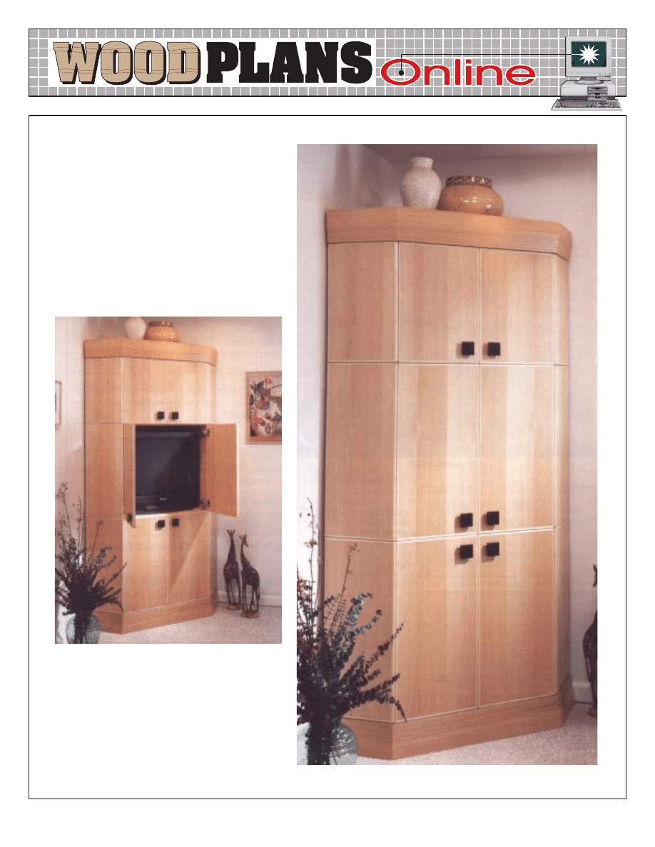
Great-looking corner-cabinet plans
are next to impossible to find. That’s
why we’re so proud to present this
one to you. Our very own Jim
Downing designed it, and should you
build it for your home, we know you’ll
be pleased with the results.
ENTERTAINMENT
CENTRAL
Store home electronics
gear in style
ENTERTAINMENT
CENTRAL
#DP-00016
TM
page 2 of 12
#8 x 1
1
/
4
" F.H. wood screws
13
3
/
8
"
70
11
/
16
"
21
3
/
16
"
80"
3
/
4
" notches
1
3
/
4
" deep
45
O
bevel
3
/
4
x 2
5
/
16
"
notches
5
/
32
" holes, counter-
sunk on bottom
3
/
4
" dadoes
1
/
4
" deep
D
A
A
A
80"
A
3
/
4
" notch
1
3
/
4
" deep
4
11
/
16
"
25
3
/
16
"
25
1
/
4
"
17
1
/
4
"
4
5
/
8
"
#8 x 1
1
/
4
" F.H. wood screws
CARCASE
1
/
4
" mounting holes (for mounting molding)
1
/
4
" mounting holes
(for mounting panels)
5
/
32
" hole,
countersunk
G
C
F
F
F
F
D
D
F
G
B
B
B
B
H
H
H
H
#8 x 1" F.H. wood screw
H
H
H
#8 x 1" F.H. wood screw
#8 x 1
1
/
4
" F.H. wood screws
#8 x 1
1
/
2
" F.H.
wood screws
1
/
4
" holes
1
/
2
" deep
for shelf
supports
2 x 10" notch
for ventilation
F
E
C
4"
Cut out openings
in back for TV,
components, wiring,
and ventilation
as necessary.
TM
page 3 of 12
1
/
2
" rabbet
1
/
2
" deep
1
/
2
" rabbet
1
/
4
" deep
Rip 45
o
miters after
panel is assembled.
1"
10
1
/
2
"
SIDE PANEL
(BACK VIEW)
1
/
4
"
3
/
4
"
W
and
O
P
and
S
T
This edge will go
next to doors.
17
/
32
"
1"
1
/
2
"
1
/
4
"
1
/
2
"
and
MITER DETAIL
(TOP VIEW)
and
S
O
T
P
45
o
miters
1
/
4
"
U
V
and
1
/
2
"
Miter end of cleat to 45
O
.
5
/
32
" holes,
countersunk
7
/
64
" pilot hole
1
/
2
" deep
3
/
4
" dado
1
/
4
" deep
45
O
bevel
#8 x 1
1
/
4
" F.H.
wood screws
A
ASSEMBLY
DETAIL
G
F
B
F
H
C
D
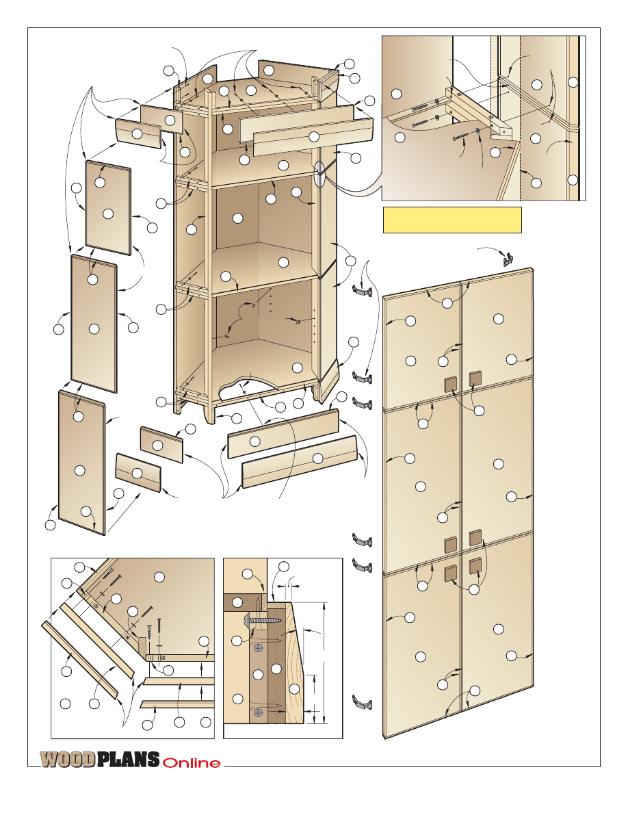
Note: We designed this cabinet to
house most 27" televisions. For some
models, though, you’ll have to remove
the hinges from the cabinet before
sliding the TV into place.
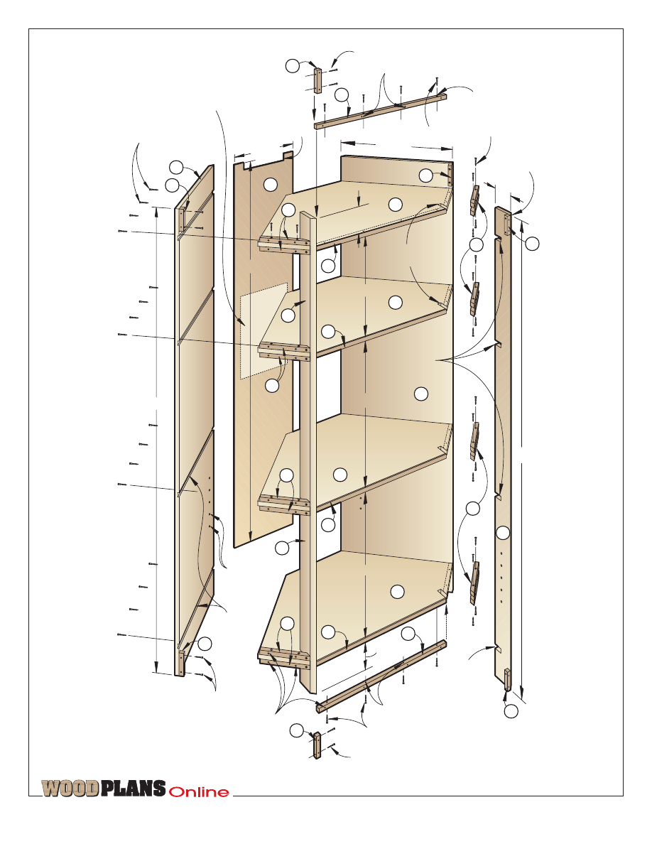
Let’s begin with four
identical shelves
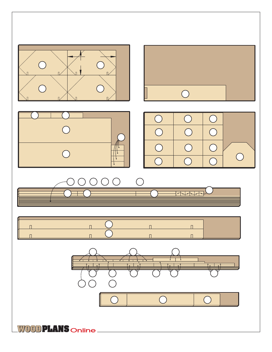
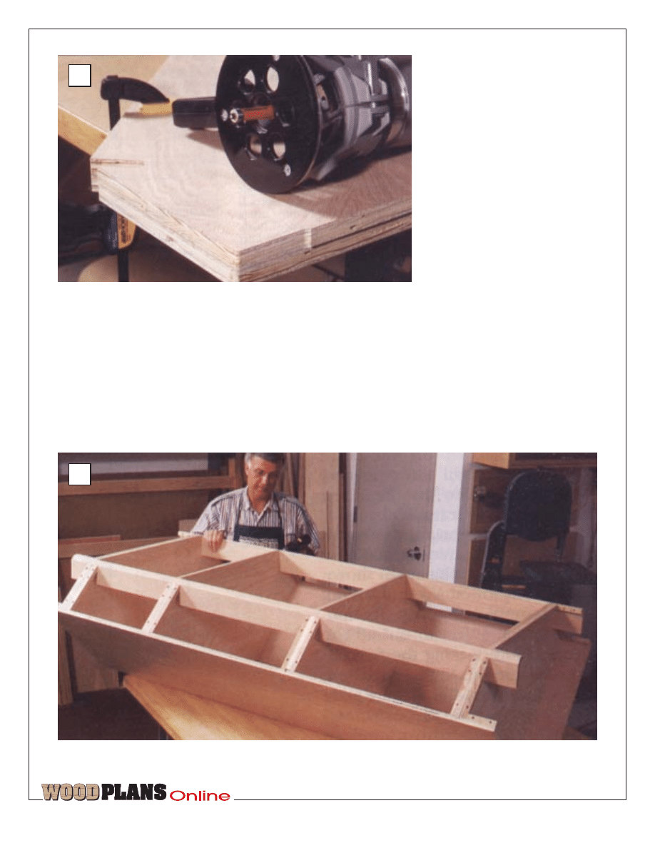
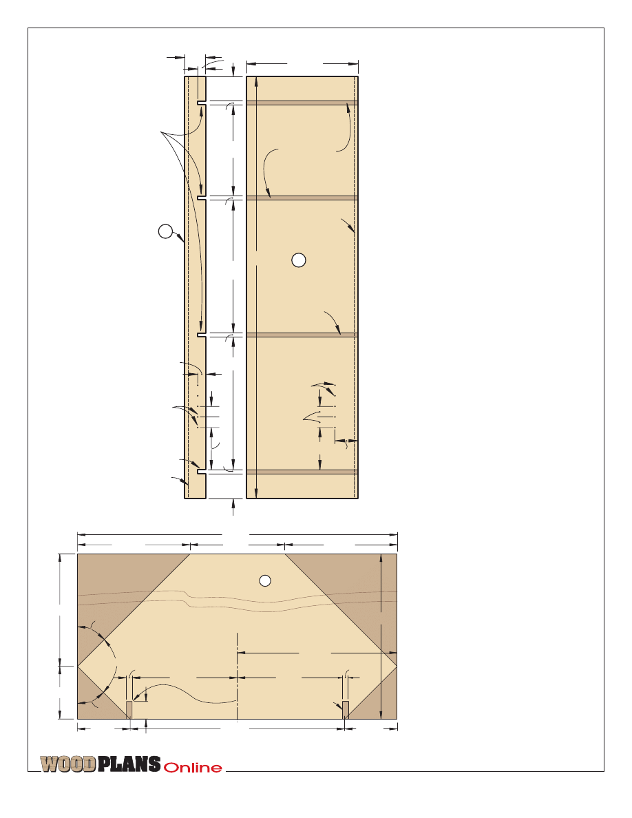
1 Using the Parts View on page 8 for
the shelf (A), lay out and cut the four
shelves to the same exact shape. See
the Cutting Diagram for how we cut
four blanks from one piece of 4
×
8
plywood. (We cut one shelf to exact
shape, and then cut the other three
slightly oversized. Then, as shown in
photo A, we used our handheld router
fitted with a piloted straight bit to rout
the other three shelves to the exact
shape of the first.)
2 Cut the banding strips (B) from solid
stock, and glue and clamp them to the
front edge of the shelves (A), making
sure the top and bottom surfaces are
flush.
Cut the carcase pieces,
and assemble the carcase
1 Cut the carcase sides (C) to 21fi
×
80".
Lay out the dadoes using the
dimensions on the Side (A) portion of
the Parts View drawing on page 8. Fit
your tablesaw with a dado blade and
cut the dadoes where marked, taking
care to keep the dadoes positioned
exactly the same in each.
2 Using your tablesaw, bevel-rip the
back edge of each cabinet side (C) to
final width (21‰") at 45°, being
careful to rip the bevel on the side
opposite the dadoes.
3 Cut the corner supports (D) to size,
bevel-ripping the front edge of each
at 45°. Mark the notch locations on
one, making sure they align with the
dadoes in the sides (C). Clamp the two
supports face-to-face, and cut the
notches in both at the same time.
4 If you plan on adding the adjustable
shelf (Z) later, drill ‹" holes fi" deep
for the shelf clips in parts C and D
where dimensioned on the Parts View
drawing.
5 From ‹" oak plywood, cut the back
TM
page 4 of 12
‡"
27‡"
‡"
‡"
G cleats
2
O
4"
‡"
13›"
‹"
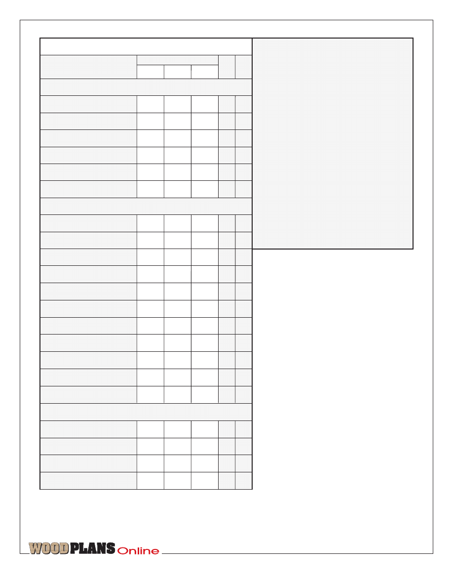
E back
1
OP
70Ø"
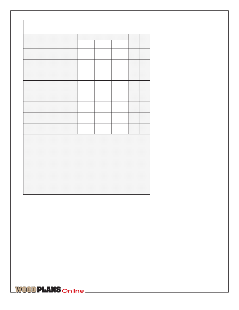
Part
O
4
B banding
27‡"
Bill of Materials for Carcase Assembly
D supports
OP
2
80"
‡"
21‰"
O
2
80"
Qty.
A shelf blanks
42¤"
‡"
21‡"
OP
4
T
W
L
Finished Size
Matl.
‹"
‡"
C* sides
F cleats
16
O
*Cut parts marked with an * oversized. Trim to finished
size according to the how-to instructions.
Materials Key: OP–oak plywood, O–oak.
Carcase Supplies: #8
×
1" flathead wood screws,
#8
×
1‹" flathead wood screws, #8
×
1fi" flathead
wood screws.
‡"
8Å"
3Œ"
‡"
‡"
H cleats
8
O
TM
page 5 of 12
3
/
4
x 48 x 96" Oak plywood
3
/
4
x 48 x 96" Oak plywood
1
/
4
x 48 x 96" Oak plywood
3
/
4
x 48 x 96" Oak plywood
(
1
/
4
x
3
/
4
" banding strips)
3
/
4
x 7
1
/
4
x 96" Maple
42
1
/
8
"
21
3
/
4
"
, , , , , and
3
/
4
x 9
1
/
4
x 96" Oak
CUTTING DIAGRAM
3
/
4
x 5
1
/
2
x 72" Oak
(
1
/
4
x
3
/
4
" banding strips)
, ,and
3
/
4
x 5
1
/
2
x 60" Oak (2 needed)
T
K
L
S
S
J
Z
O
O
P
O
O
P
Q
Q
R
Q
Q
R
Y
C
A
A
A
A
C
I
I
D
D
H
H
AA
B
CC
M
N
N
E
V
U
W
X
F
G
F
G
F
F
BB
TM
page 6 of 12
(E) to size. When attached later, the
top of the back panel is flush with the
top of the top shelf, and the bottom of
the back panel is flush with the bottom
of the bottom shelf.
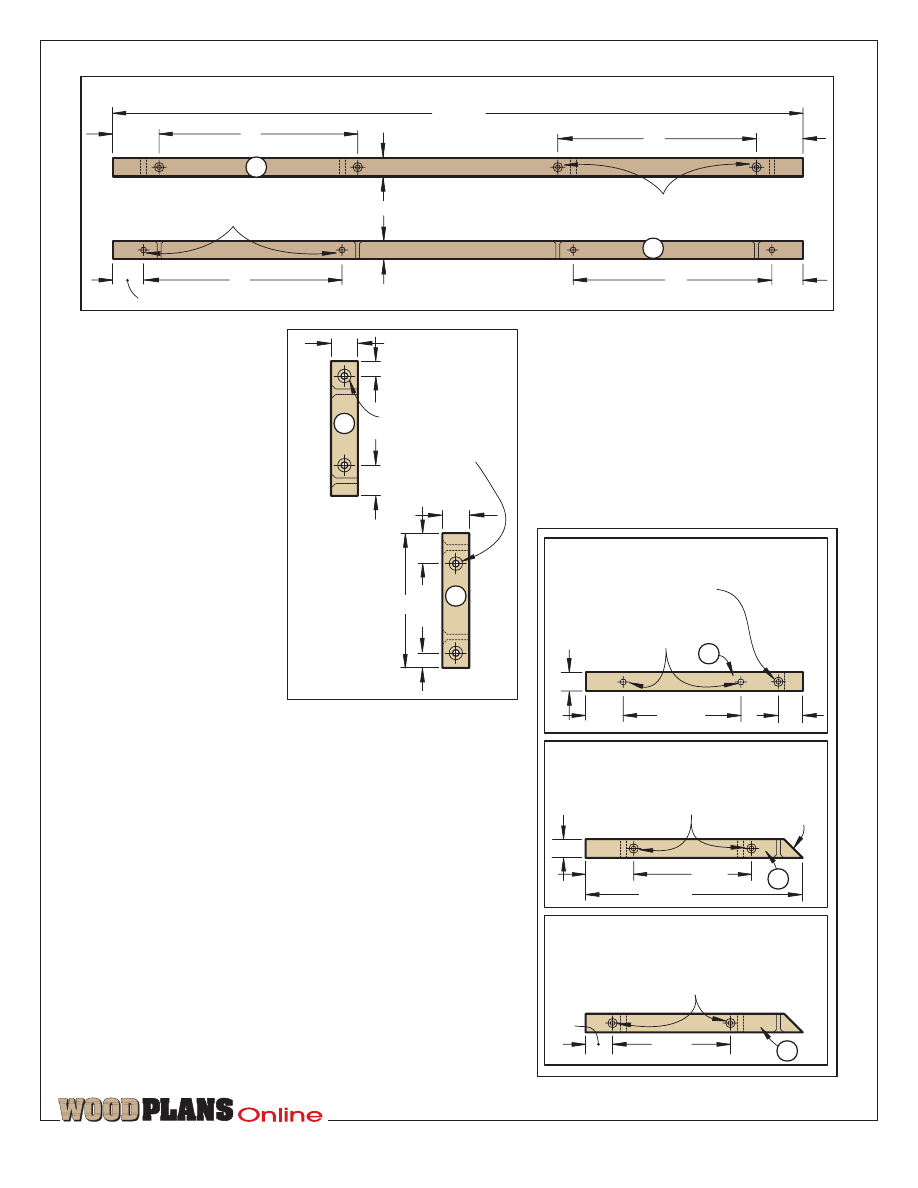
6 Cut cleats (F, G, H) to the sizes listed
in the Bill of Materials. Drill the
mounting holes in the cleats where
dimensioned on Drilling the Cleats
drawing on page 7.
7 Glue and screw the cleats (F, G, H)
in place.
8 Connect the sides (C) to the shelves
(A, B). Drill countersunk screw holes
from the outside of the side pieces,
and screw the assembly together,
checking for square.
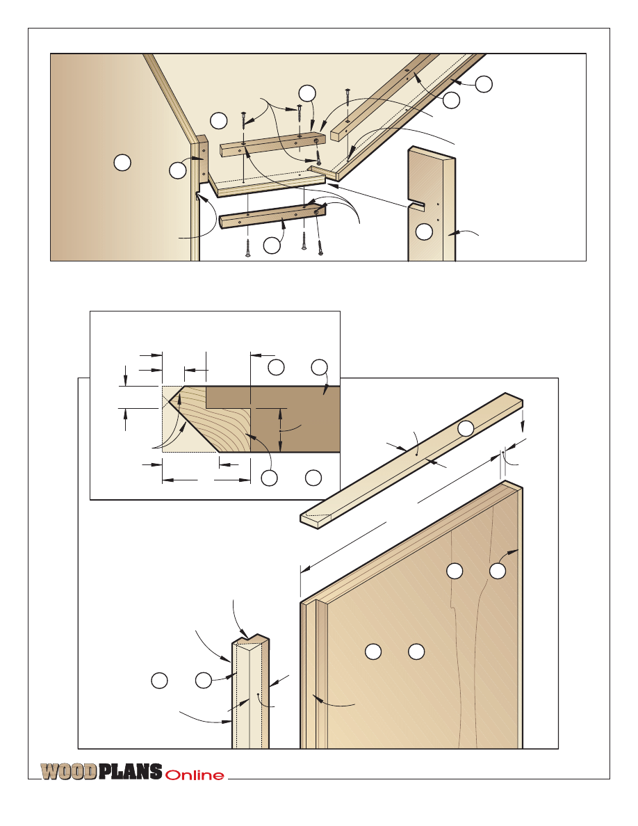
9 Slide the supports (D) into the shelf
notches. Screw through the cleats (F)
to secure the supports in place as
shown in photo B and in the Assembly
detail accompanying the Carcase
drawing.
Here’s how to make the
top and bottom moldings
1 Cut the front filler pieces (I, J) and
mating banding strips (K, L) to the
sizes listed in the Bill of Materials plus
1" in length. Glue and clamp a banding
strip to one edge of each filler piece.
Later, scrape off the excess glue, and
sand the faces smooth.
2 To get the grain of the molding to
wrap around the cabinet, cut two strips
of solid stock to 5" wide by 54fi" long
for molding pieces M and N as laid
out on the Cutting Diagram. With the
edges flush, glue and clamp the banded
filler strips to the back side of the
molding pieces. Remove any excess
glue with a damp cloth.
3 Tilt your tablesaw blade 9° from
vertical, and bevel-rip one face of each
laminated molding strip to achieve a
profile on the solid stock like that
shown on the Side Section-View detail
accompanying the Exploded View
drawing. Sand the beveled-cut area
smooth.
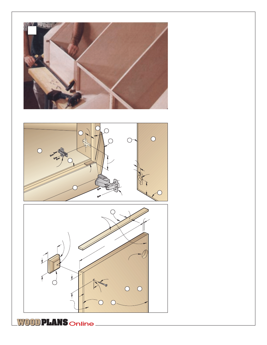
Using your first shelf as a template, rout the final shelves to finished
shape with a router fitted with a piloted straight bit.
Secure the notched supports to the previously installed shelves by driving wood screws through the
previously drilled cleats.
A
B
TM
page 7 of 12
TOP VIEW
FRONT VIEW
FRONT FILLER CLEAT
5
/
32
" countersunk holes, centered on edge
1
/
4
" mounting holes, centered on edge
2"
2"
1
1
/
4
"
1
1
/
4
"
3
/
4
"
27
3
/
4
"
8"
8"
8"
8"
G
G
3
/
4
"
FRONT
VIEW
5
/
32
" countersunk
holes, centered
on edge
SIDE
VIEW
3
/
8
"
3
/
4
"
3
/
4
"
3
7
/
8
"
3
/
4
"
3
/
8
"
3
/
4
"
H
H
PARTS VIEW
3
/
4
"
45
o
miter
4
7
/
8
"
1
7
/
8
"
1
/
4
" mounting holes,
centered on edge
1
1
/
8
"
Drill the other 8 pieces
using these dimensions.
5
/
32
" holes, centered on edge
Countersunk on both sides.
4
7
/
8
"
8
13
/
16
"
3
/
4
"
FRONT
VIEW
4
7
/
8
"
1
1
/
2
"
1"
F
Drill 8 pieces using
these dimensions.
5
/
32
" holes, centered on edge
Countersunk on both sides.
Drill all 16 pieces using
these dimensions.
5
/
32
" countersunk hole,
centered on edge
F
TOP
VIEW
TOP
VIEW
DRILLING THE CLEATS
F
4 Cut and miter-cut the
laminated molding strips to
wrap around the carcase in the
configuration shown on the
Exploded View drawing and
accompanying Top Section-
View detail. (We laid out all
the pieces before making the
first cut to make sure the
angled cuts were correctly
located and that the grain
wrapped around the cabinet.)
When cutting these pieces to
length, make sure to cut them
to fit your cabinet and not
necessarily to the dimensions
we provide.
5 Drive screws through the
cleats to temporarily screw the
molding pieces in place with
just two screws per section. You may need to adjust the location of
the moldings later when aligning them with the side panels and doors,
so you’ll drive the remaining screws then.
The banded side panels
and doors come next
1 Using the Cutting Diagram for reference, mark reference marks on
your plywood for the side panels (O, P) and doors (Q, R). By marking
them now, it’s easier to keep them properly oriented for placing on
the cabinet so the grain runs from the top of the cabinet to the bottom.
(For the striking looks of our cabinet, we selected a sheet of straight-
grained oak plywood for our panels and doors.) Cut the panels to exact
size. (Use a sharp carbide-tipped blade to minimize chip-out when
cutting the plywood.)
2 From solid maple, cut the edge banding (S, T, U, V) to size plus 1"
in length.
3 Cut a fi" rabbet fi" deep along the back side of the edge that will
go next to the doors in the side panels (O, P) where shown on the Side
Panel drawing and accompanying detail. It’s easy to cut the rabbets
in the wrong spot, so we recommend marking them before machining.
TM
page 8 of 12
45
o
45
o
14
13
/
16
"
12
1
/
2
"
6
15
/
16
"
3
/
4
"
Centerline
21
3
/
4
"
3
/
4
" notches 2
5
/
16
" deep
Waste is
shaded
darker.
SHELF
42
1
/
8
"
3
/
4
"
90
o
14
13
/
16
"
28
1
/
4
"
13
7
/
8
"
13
7
/
8
"
21
1
/
16
"
6
15
/
16
"
6
15
/
16
"
14
13
/
16
"
2
5
/
16
"
A
3
/
4
" dadoes
1
/
4
" deep
45
o
bevel along
back edge
45
o
bevel
3
/
4
" notches
1
3
/
4
" deep
4"
21
3
/
16
"
3
/
4
"
4
5
/
8
"
4
11
/
16
"
80"
FRONT
CORNER
SUPPORTS
SIDE
8"
2"
1
/
4
" holes
1
/
2
" deep
spaced
2" apart
8"
2"
4
1
/
4
"
1
/
4
" holes
1
/
2
" deep
spaced
2" apart
3
/
4
" dado
1
/
4
" deep
17
1
/
4
"
25
1
/
4
"
25
3
/
16
"
3
/
4
"
3
/
4
" notch
1
3
/
4
" deep
1
1
/
2
"
2"
C
3
/
4
"
3
/
4
"
D
Then, cut a fi" rabbet ‹" deep along
the mating edge of the banding strips
(S, T).
4 Glue and clamp the maple banding
(S, T, U, V) to the edges (not ends) of
the doors and side panels (O, P, Q, R).
Trim the banding flush with the ends
of the doors, and then glue and clamp
the end banding (W, X) in place. Later,
trim its ends flush.
5 Sand the edges of the banding flush
with the front and back of each panel
and door, being extremely careful not
to sand through the veneer.
6 Using the Miter detail accompanying
the Side Panel drawing on page 3 for
reference, bevel-rip the wide banding
on the side panels.
Now, install the banded
side panels and doors
1 Using the Ï" spacers as shown in
photo C, position, clamp, and screw a
bottom side panel in place. Repeat to
add the center, and then the top side
panels. Repeat for the other side of the
cabinet. At this point, you may need
to adjust the location of the molding
(up and down) for equal gaps between
all the pieces.
2 With the location of the molding
verified with the doors and panels,
glue, clamp, and screw the molding in
place, using the spacers for alignment
and consistent spacing.
3 See the Buying Guide for our source
of hinges. If you use different hinges,
the mounting holes and mounting
instructions will probably differ. Using
the instructions supplied with the
hinges and the dimensions on the
Mounting the Doors drawing, mark
the hole centerpoints on the back of
each door.
4 Fit your drill press with a 1›"
Forstner bit stopped to drill fi" deep.
Then, fit your drill press with a fence
to accurately locate the holes Å"
from the edge. Test-drill scrap ‡"
plywood first to verify that the point
of the bit doesn’t go completely
through the plywood. (We found that
the points on one set of our Forstners
had to be filed down.)
PARTS VIEW
1
3
/
4
"
‡"
12
M
M
6
‹"
‹"
‡"
‡"
17›"
13‡"
OP
2
17›"
10fi"
TM
page 9 of 12
N* molding
V* banding
Qty.
Bill of Materials
‡"
OP
2
Part
T
W
L
Finished Size
Matl.
‡"
4‡"
2
J* filler strips
K* banding
10Œ"
L* banding
‡"
O
M* molding
‡"
5"
*Cut parts marked with an * oversized.
Trim to finished size according to the
how-to instructions.
Materials Key:
OP–oak plywood,
O–oak, M–maple.
Supplies: #8
×
1‹" flathead wood screws,
#8
×
1fi" flathead wood screws, #8
×
1‹"
panhead wood screws with flat washers,
hinges (see description below), brass
shelf supports, gloss black paint, clear
finish.
Buying Guide
Hinges. Self-closing 165° Grass
concealed hinges. Six pair needed.
Catalog no. CH1202. For current price,
contact Constantine, 2050 Eastchester
Road, Bronx, NY 10461, or call 800/223-
8087 or 718/792-1600 to order.
‡"
P panels
‡"
Q doors
‡"
R doors
‡"
S* banding
‡"
T* banding
U* banding
X* banding
‡"
6
Y handles
I* filler strips
‹"
‹"
‹"
MOLDINGS
PANELS AND DOORS
4‡"
‡"
‡"
5"
13‹"
13‹"
1"
1"
‡"
2"
28Á"
10Œ"
28Á"
29„"
11‹"
25›"
17›"
25›"
17›"
25›"
2"
OP
M
M
O
OP
OP
M
M
M
M
4
4
4
2
4
2
4
2
12
OP
4
25›"
10fi"
‡"
O panels
M
12
‹"
‡"
11‹"
W*banding
‡"
1
21›" 27¤" OP
‹"
1
AA banding
‡"
27fl"
O
‹"
2
BB banding
‡"
14"
O
2
CC cleats
1fi"
10"
O
ADJUSTABLE SHELF
Z
shelf
TM
page 10 of 12
J
A
A
A
A
E
Corners along this
edge of cabinet have
no miters (they are 90
o
).
22.5
o
miters
#8 x 1
1
/
4
" panhead wood screws
with #10 flat washers
*45
o
miters
22.5
o
miters
*45
o
miter
#8 x 1
1
/
4
" panhead
wood screw with
#10 flat washer
165
O
self-closing inset hinges
(see Mounting the Doors drawing)
I
PANEL
MOUNTING DETAIL
C
*45
o
miter
7
/
64
" pilot
holes
1
/
2
" deep
1
/
4
" mounting hole
Space panels
3
/
32
" apart (use
spacer blocks).
#8 x 1
1
/
4
" panhead
wood screw
#10 flat washer
A
22.5
o
miters
SIDE SECTION-VIEW DETAIL
TOP SECTION-VIEW DETAIL
22.5
o
miters
A
F
A
1
/
4
"
5"
2"
3
/
4
"
EXPLODED VIEW
S
O
N
M
I
G
F
D
C
B
B
B
B
D
F
F
G
J
K
H
L
D
B
S
B
G
G
D
M
#8 x 1
1
/
4
" F.H. wood screw
N
O
V
U
R
W
X
Y
Q
P
P
T
U
S
W
W
W
N
J
L
M
K
P
T
O
V
V
V
X
X
X
Y
U
R
Q
Q
Q
N
U
U
U
U
U
H
9
o
K
I
H
M
N
J
and
L
H
C
H
Drill
7
/
64
" pilot holes
1
/
2
" deep for
#8 panhead and F.H. wood screws.
Brass shelf
supports
C
O
I
and
K
D
*NOTE: See profile on Side Panel
drawing for miter configuration.
and
2"
2"
2"
2"
3
/
8
" cove
3
/
8
" deep
7
/
64
" pilot hole
1
/
2
" deep, centered
1
/
4
x
3
/
4
" banding along
all edges of doors
13
1
/
4
"
Hinge mounting hole
(see Mounting the Doors
drawing above for location)
#8 x 1
1
/
4
" F.H.
wood screw
5
/
32
" hole, countersunk
Back side of door
DOOR
1
/
4
"
3
/
4
"
and
13
/
16
"
2
1
/
2
"
1
3
/
8
" hole
1
/
2
" deep
Back side
of door
3
/
32
" pilot hole
3
/
8
" deep
165
o
self-closing
inset hinge
base plate
3
/
32
x
3
/
4
x 1
1
/
2
"
spacer block
Inside of cabinet
MOUNTING
THE DOORS
2
1
/
2
"
2
1
/
4
"
165
o
self-closing inset hinge
U
X
M
D
B
A
O
X
V
U
R
Y
Q
Q
S
N
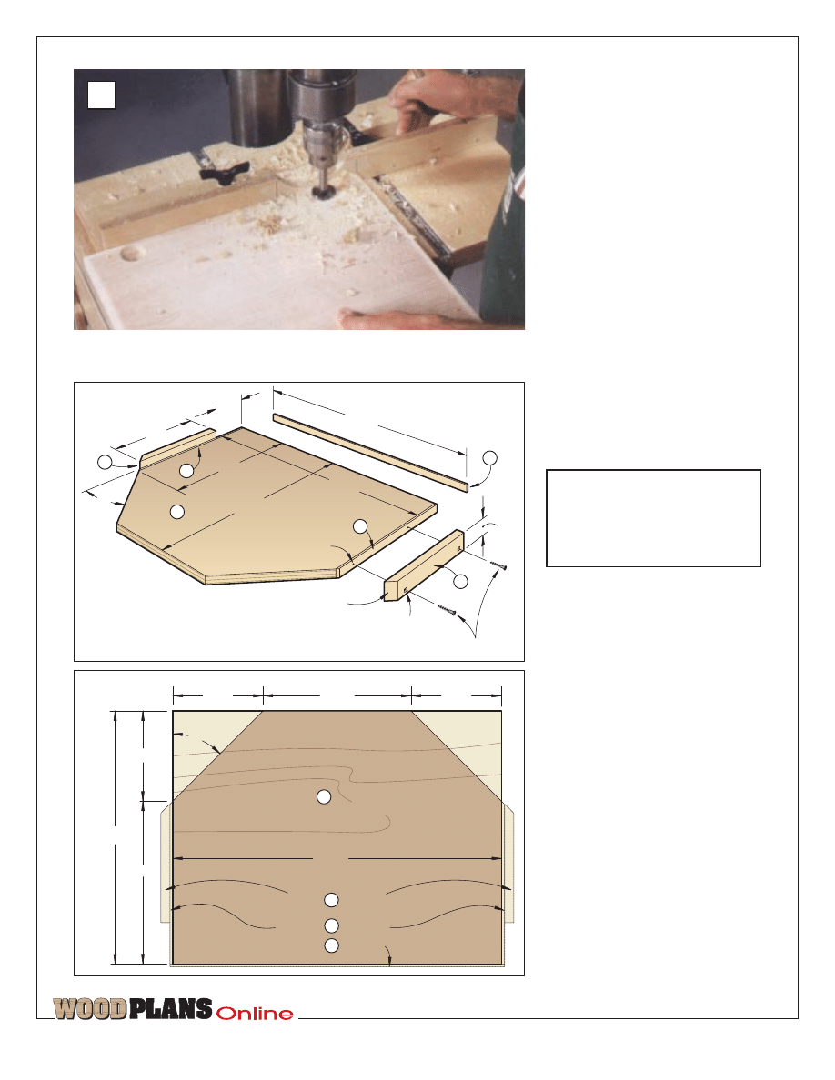
Bore the hinge holes where marked
and as shown in photo D. (Notice how
we marked stop lines on our drill-press
fence to keep the holes exactly 2fi"
from the top and bottom ends of the
doors.)
5 Fit the hinges into the holes just
bored in the back face of the doors.
Using the screws supplied with the
hinges, drill pilot holes, and screw the
hinges in place.
6 Attach the base plate of each hinge
to the carcase. See the Mounting the
Doors drawing for reference.
Following the instructions supplied
with the hinges, fit the hinge on the
base plate, and secure in place. Make
the alignment adjustments as explained
in the instructions.
It’s time to machine
the door handles
1 From ‡" maple, cut seven 2" squares
for the handles (Y). Use the extra
handle blank to verify your machine
settings in the following steps before
machining the other handle blanks.
2 Fit your table-mounted router with
a ›" cove bit and fence. With the good
side up, rout the end grain first on each
handle blank to reduce chip-out. (To
safely hold the 2"-square handles when
routing, we used a wood handscrew
clamp.) Next, rout the adjoining two
edges on each handle blank.
3 Using your drill press with a fence
and stop, drill a
7
⁄
64
"pilot hole centered
on the back side of each handle. See
the Door drawing for reference. Sand
the handles smooth.
OK, let’s add the
shelf and the finish
1 For additional storage, construct the
shelf (Z, AA, BB, CC) in the
configuration shown on the Adjustable
Shelf drawing. To allow us to get all
the panels and shelf (Z) from one piece
of plywood, we banded the ends to get
the necessary length.
2 Remove the hinges from the cabinet
and doors. To ensure correct placement
w h e n r e a s s e m b l i n g , m a r k
corresponding marks on the hinges
and their mating holes.
TM
page 11 of 12
With the cabinet on its back, use spacers to create equal gaps
between the molding and banded side panels.
C
3 Remove the knobs and spray-paint
them a gloss black.
4 The back of the cabinet (E) should
still be off. If not, remove it; it’s easier
to finish the cabinet with the back
panel not in place. Determine what
you’ll need for cord holes through the
back, and cut the access holes.
Depending on your television, you also
may need to cut an opening through
the back (E) for the rear of your
television to extend through. Sand the
back smooth.
5 Apply finish to all the pieces. (We
applied three coats of semigloss
lacquer, sanding between coats.)
6 Reattach the hinges and handles.
Screw the back panel in place.¿
TM
page 12 of 12
Cleat locations
Banding location
Banding locations
ADJUSTABLE SHELF
45
o
14"
7
3
/
8
"
Z
BB
AA
14"
3
3
/
4
"
10"
45
o
bevel
#8 x 1
1
/
2
" F.H. wood screws
5
/
32
" shank hole, countersunk
7
/
64
" pilot hole
3
/
4
" deep
ADJUSTABLE SHELF
45
O
27
1
/
8
"
Z
BB
CC
BB
CC
27
5
/
8
"
1
1
/
2
"
AA
21
3
/
8
"
12
3
/
8
"
7
3
/
8
"
7
3
/
8
"
21
3
/
8
"
27
1
/
8
"
CC
SHELF
LAYOUT
D
Mark the centerpoints on the doors, and bore a pair of holes in the
back side of each door for attaching the hinges later. A fence keeps
the holes aligned.
Produced by Marlen Kemmet
Project Design: James R. Downing•
Illustrations: Kim Downing, Lorna Johnson
Graphic Design: Jamie Downing
©COPYRIGHT MEREDITH CORPORATION 1998
The purchase of these plans does not
transfer any copyright or other ownership
interest in the plans, the design, or the
finished project to the buyer. Buyer may
neither reproduce the plans for sale nor
offer for sale any copies of the finished
project.
Wyszukiwarka
Podobne podstrony:
Cabinet entertainment center2
Cabinet Entertainment Center
Cabinet entertainment center1
Cabinet entertainment center3
Cabinet Shaker entertainment center
Cabinet Modular Entertainment Center
Cabinet small entertainment center
Entertainment Center (2)
Cabinets Bar Plans
Cabinet Video Game Center (Part 1)
Cabinet Video Game Center (Part 2)
(Ebooks) Diy Woodwork Plans Kitchen Cabinets
Wood Working Plan Arcade Cabinet Plans
Cabinet Fold Away Hobby Center(Part 2)
Cabinet Fold Away Hobby Center(Part 1)
Cabinet Buffet And China Cabinet Plans
więcej podobnych podstron