POWER MIRRORS
CONTENTS
page
page
GENERAL INFORMATION
. . . . . . . . . . . . . . . . . . 1
HEATED MIRROR
. . . . . . . . . . . . . . . . . . . . . . . . 1
MIRROR ASSEMBLY REPLACEMENT . . . . . . . . . 2
MIRROR MOTOR TEST . . . . . . . . . . . . . . . . . . . . 1
MIRROR SWITCH REPLACEMENT
. . . . . . . . . . . 2
MIRROR SWITCH TEST
. . . . . . . . . . . . . . . . . . . 1
GENERAL INFORMATION
Electrically-operated remote control mirrors are
available as an option on AS-body vehicles. The mir-
rors are controlled by a switch assembly located on
the driver’s door armrest bezel.
The vehicle use a rocker switch for right or left side
mirror selection and four buttons for mirror UP,
DOWN, RIGHT, or LEFT movement.
The motors which operate the mirrors are part of
the mirror assembly and cannot be serviced sepa-
rately.
MIRROR MOTOR TEST
(1) Remove door trim panel. Refer to Group 23,
Body.
(2) Disconnect wiring harness connector to the
Power Mirror.
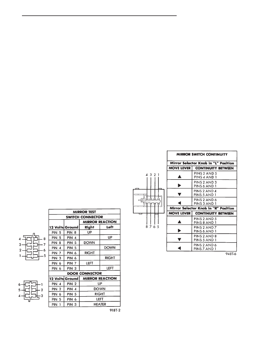
(3) Using two jumper wires:
• Connect one to a 12-volt source
• Connect the other to a good body ground
• Refer to the Mirror Test Chart for wire hookups at
the switch connector (Fig. 1).
(4) If results shown in chart are not obtained,
check for broken or shorted circuit, or replace mirror
assembly as necessary.
MIRROR SWITCH TEST
(1) Remove power mirror switch from mounting po-
sition.
(2) Disconnect wiring harness at switch connector.
(3) Using a ohmmeter, test for continuity between
the terminals of the switch as shown in the Mirror
Switch Continuity Chart (Fig. 2).
If results shown in the chart are not obtained, re-
place the switch.
HEATED MIRROR
Heated mirrors are available on some models with
Power Mirrors and Rear Window Defogger only. The
heated mirror is controlled by the rear window defog-
ger switch. The heated mirror is on when the rear
window defogger is on.
Fig. 1 Power Mirror Test
Fig. 2 Mirror Switch Test
.
POWER MIRRORS
8T - 1

TEST PROCEDURES
(1) The mirror should be warm to the touch.
(a) If not check fuse #8 in the power distribution
center and relay #9 in relay block.
(b) Test voltage at rear window defogger switch.
• If no voltage repair wire.
• Apply voltage to one wire and ground the other, re-
fer to Fig. 1 for pin numbers. Mirror should become
warm to the touch.
• If not remove mirror glass and test the wires for
continuity. If no continuity repair wires.
• If wires are OK, replace mirror glass.
• To test defogger switch refer to Group 8N, Rear
Window Defogger.
MIRROR SWITCH REPLACEMENT
(1) Remove driver’s door mirror switch bezel from
armrest (Fig.3).
(2) Disconnect wiring connector.
(3) Remove switch from bezel.
(4) For installation, reverse above procedures.
MIRROR ASSEMBLY REPLACEMENT
(1) Remove door trim panel and weather shield.
Refer to Group 23, Body.
(2) Reach inside door and disconnect mirror wiring
at connector.
(3) Remove three mirror retaining nuts (Fig. 4).
(4) Pull mirror loose from door, and feed wiring
harness out through hole in outer door panel.
(5) For
installation,
reverse
above
procedures.
Fig. 4 Power Mirror
Fig. 3 Power Mirror/Window switch Bezel
8T - 2
POWER MIRRORS
.
Document Outline
Wyszukiwarka
Podobne podstrony:
(3) 8t?ssonville
opracowanie 8T#2
opracowanie 8T#1
EZG 8T
94AS 8N
94AS 8C
A4 1996 AEB 1 8T ABS
Miernik masowego przepływu powietrza 1 8T AGU
ROZDZ 8T, PW SiMR, Inżynierskie, Semestr V, syf, laborki, Uklady napedowe, MTMT
94AS 8R
94AS 8H
94AS 22
94AS 25
94AS 8J
94AS 8M
94AS 8A
94AS 8B
opracowanie 8T#1
[ABC]Diagnostyka 1 8 20V TURBO AEB APU AWT AWM 1 8T krok po kroku [GUIDE] v 0
więcej podobnych podstron