
ELECTRICAL
GROUP INDEX
group
group
AUDIO SYSTEM . . . . . . . . . . . . . . . . . . . . . . . . . 8F
BATTERY/STARTER/GENERATOR SERVICE
BATTERY/STARTING/CHARGING SYSTEMS
. . . . . . . . . . . . . . . . . . . . . . . . 8A
CHIME WARNING/REMINDER SYSTEM . . . . . . 8U
HORNS
. . . . . . . . . . . . . . . . . . . . . . . . . . . . . . . 8G
. . . . . . . . . . . . . . . . . . . . . 8D
POWER MIRRORS . . . . . . . . . . . . . . . . . . . . . . . 8T
POWER SEATS
. . . . . . . . . . . . . . . . . . . . . . . . . 8R
. . . . . . . . . . . . . . . . . . . . . . . . . . . . 8J
VEHICLE SPEED CONTROL SYSTEM . . . . . . . . 8H
WINDSHIELD WIPERS AND WASHER
SYSTEMS . . . . . . . . . . . . . . . . . . . . . . . . . . . . 8K
WIRING DIAGRAMS . . . . . . . . . . . . . . . . . . . . . 8W
BATTERY/STARTING/CHARGING SYSTEMS DIAGNOSTICS
CONTENTS
page
page
BATTERY TEST PROCEDURES ON-VEHICLE
. . . 3
DIAGNOSTIC CODES—ON BOARD DIAGNOSTICS . 21
GENERAL INFORMATION
. . . . . . . . . . . . . . . . . . 1
GENERATOR TEST PROCEDURES ON VEHICLE
IGNITION OFF DRAW (IOD)
. . . . . . . . . . . . . . . . 8
SPECIFICATIONS . . . . . . . . . . . . . . . . . . . . . . . . 25
STARTER TEST PROCEDURES ON VEHICLE
. . 10
GENERAL INFORMATION
For Battery, Starter or Generator Replacement, re-
fer to Group 8B, Battery/Starter/Generator Service.
Group 8A, Battery/Starting/Charging Systems Diag-
nostics will cover diagnostics only.
The Battery, Starting, and Charging Systems oper-
ate in conjunction with one another, and must be
thoroughly tested as a complete system. To enable
the vehicle to start and charge properly, it must have
a battery that will perform to specifications. The
starter motor, generator, wiring, and electronics also
must perform within specifications. Group 8A will
cover Starting (Fig. 1) and Charging System (Fig. 2)
diagnostic procedures. These will be covered from the
most basic conventional methods to On Board Diag-
nostics (OBD) built into the vehicle’s electronics. The
need for conventional testing equipment has not been
eliminated by the introduction of OBD. Frequent use
of an ammeter, volt/ohmmeter, battery charger, car-
bon pile rheostat (load tester), and 12 volt (low watt-
age) test light will be required.
All front wheel drive vehicles are equipped with
OBD and all OBD sensing systems are monitored by
the Powertrain Control Module. The powertrain con-
trol module will store in electronic memory, any de-
tectable failure within the monitored circuits. It will
retain this information for a period of 50 engine
.
ELECTRICAL
8A - 1
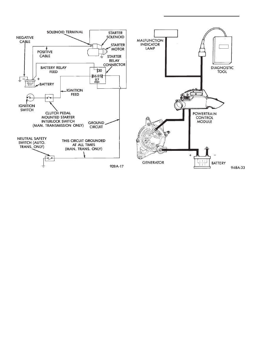
The Malfunction Indicator (Check Engine) Lamp on
the instrument cluster will flash in predetermined
sequences to show Diagnostic Codes. However, the
Malfunction Indicator (Check Engine) Lamp cannot
express diagnostic codes for all failures. Diagnostic
codes are easier to obtain and more complete with
the use of Diagnostic Tool (DRB). This tool is plugged
into the diagnostic connector located in the engine
compartment (Fig. 2). Refer to the instructions pro-
vided with the DRB tool being used.
For numbered Diagnostic Codes pertaining to com-
ponents within this particular Group, refer to Diag-
nostic Codes—On Board Diagnostics in Group 8A.
For other numbered Diagnostic Codes not pertaining
to this Group (8A), refer to On Board Diagnostics in
the General Diagnosis section of Group 14, Fuel Sys-
tem for more information.
Fig. 1 Starting System Components
Fig. 2 Charging System Components
8A - 2
BATTERY/STARTING/CHARGING SYSTEMS DIAGNOSTICS
.
BATTERY TEST PROCEDURES ON-VEHICLE
INDEX
page
page
Battery Charging . . . . . . . . . . . . . . . . . . . . . . . . . . . 6
Battery Load Test
. . . . . . . . . . . . . . . . . . . . . . . . . . 5
Battery Open Circuit Voltage Test
. . . . . . . . . . . . . . 4
Causes of Battery Discharging
. . . . . . . . . . . . . . . . 4
General Information
. . . . . . . . . . . . . . . . . . . . . . . . 3
State of Charge Tests . . . . . . . . . . . . . . . . . . . . . . . 4
Test Indicator
. . . . . . . . . . . . . . . . . . . . . . . . . . . . . 3
GENERAL INFORMATION
The battery stores, stabilizes, and produces electri-
cal current to operate various electrical systems in
the vehicle. The determination of whether a battery
is good or bad is made by its ability to accept a
charge. It also must produce high-amperage current
output over an extended period to be able to start the
vehicle. The capability of the battery to store electri-
cal current comes from a chemical reaction. This re-
action takes place between the sulfuric acid solution
electrolyte and the lead +/- plates in each cell of the
battery. As the battery discharges, the plates react
with the acid from the electrolyte. When the charging
system charges the battery, the water is converted to
sulfuric acid in the battery. The amount of acid, spe-
cific gravity in the electrolyte can be measured with
a
hydrometer.
The
factory
installed
battery
is
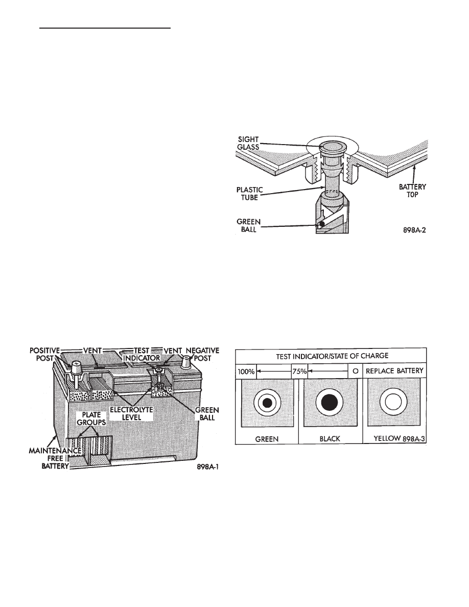
equipped with a built-in hydrometer, as a test indica-
tor (Figs. 3, 4 and 5) to assist in decide its state of
charge. The factory installed battery is also sealed.
Water cannot and should not be added.
The battery is vented to release gases that are cre-
ated when the battery is being charged and dis-
charged. The battery top, posts, and terminals should
be cleaned when other under hood maintenance is
performed (Fig. 3).
WARNING: DO NOT ASSIST BOOST, CHARGE, ADD
WATER, OR LOAD TEST BATTERY WHEN ELEC-
TROLYTE LEVEL IS BELOW THE TOP OF THE
PLATES. PERSONAL INJURY MAY OCCUR.
When the electrolyte level is below the top of the
plates a yellow or bright color indicator in sight glass
(Figs. 4 and 5), the battery must be replaced. Refer
to Test Indicator. The battery must be completely
charged with a green color in sight glass. The top,
posts, and terminals should be properly cleaned be-
fore diagnostic procedures are performed. Also refer
to Group 8B, Battery/Starter/Generator Service for
additional information.
TEST INDICATOR
A test indicator a hydrometer viewed through a
sight glass, is built into the top of battery case (Figs.
3, 4 and 5). This provides visual information for bat-
tery testing. The test indicator sight glass is to be
used with diagnostic procedures described in this
Group.
It is important when using the Test Indicator that
the battery be level and have a clean top to see the
correct indications. A light may be required to view
the Indicator.
Fig. 4 Built in Test Indicator
Fig. 3 Battery Construction and Test Indicator
Fig. 5 Test Indicator Sight Glass
.
BATTERY/STARTING/CHARGING SYSTEMS DIAGNOSTICS
8A - 3
WARNING: DO NOT USE OPEN FLAME NEAR BAT-
TERY. EXPLOSIVE GASES FORM ABOVE BATTERY.
STATE OF CHARGE TESTS
USING TEST INDICATOR
The built-in test hydrometer (Figs. 3, 4 and 5) measures
the specific gravity of the electrolyte. Specific Gravity
(SG) of the electrolyte will show state-of-charge (voltage).
The test indicator WILL NOT show cranking capacity of
the battery. Refer to Battery Load Test for more informa-
tion. Look into the sight glass (Figs. 4 and 5) and note the
color of the indicator (Fig. 5). Refer to the following de-
scription as color show:
• GREEN = 75 to 100
• state-of-charge
The battery is adequately charged for further testing
and may be returned to use. If the vehicle will not
crank for a maximum 15 seconds, refer to BATTERY
LOAD TEST in this Group for more information.
BLACK OR DARK = 0 to 75
state-of-charge
The battery is INADEQUATELY charged and must
be charged until green dot is visible, (12.4 volts or
greater) before the battery is tested or returned to
use. Refer to Causes of Battery Discharging in this
Group for more information.
YELLOW OR BRIGHT COLOR = Battery must be
replaced.
WARNING: DO NOT CHARGE, ASSIST BOOST,
LOAD TEST, OR ADD WATER TO THE BATTERY
WHEN YELLOW OR BRIGHT COLOR DOT IS VISI-
BLE. PERSONAL INJURY MAY OCCUR.
A yellow or bright color dot shows electrolyte level
in battery is below the test indicator (Fig. 5). Water
cannot be added to a maintenance free battery. The
battery must be replaced. A low electrolyte level may
be caused by an over charging condition. Refer to
Generator Test Procedures on Vehicle.
CAUSES OF BATTERY DISCHARGING
It is normal to have a small 5 to 30 milliamperes contin-
uous electrical draw from the battery. This draw will take
place with the ignition in the OFF position, and the cour-
tesy, dome, storage compartments, and engine compart-
ment lights OFF. The continuous draw is due to various
electronic features or accessories that require electrical cur-
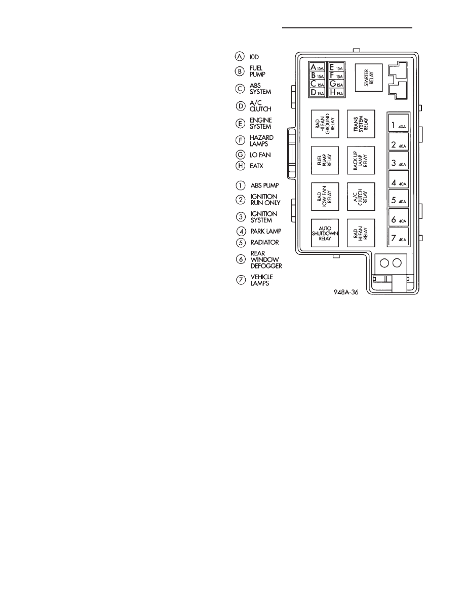
rent with the ignition OFF to function properly. When a ve-
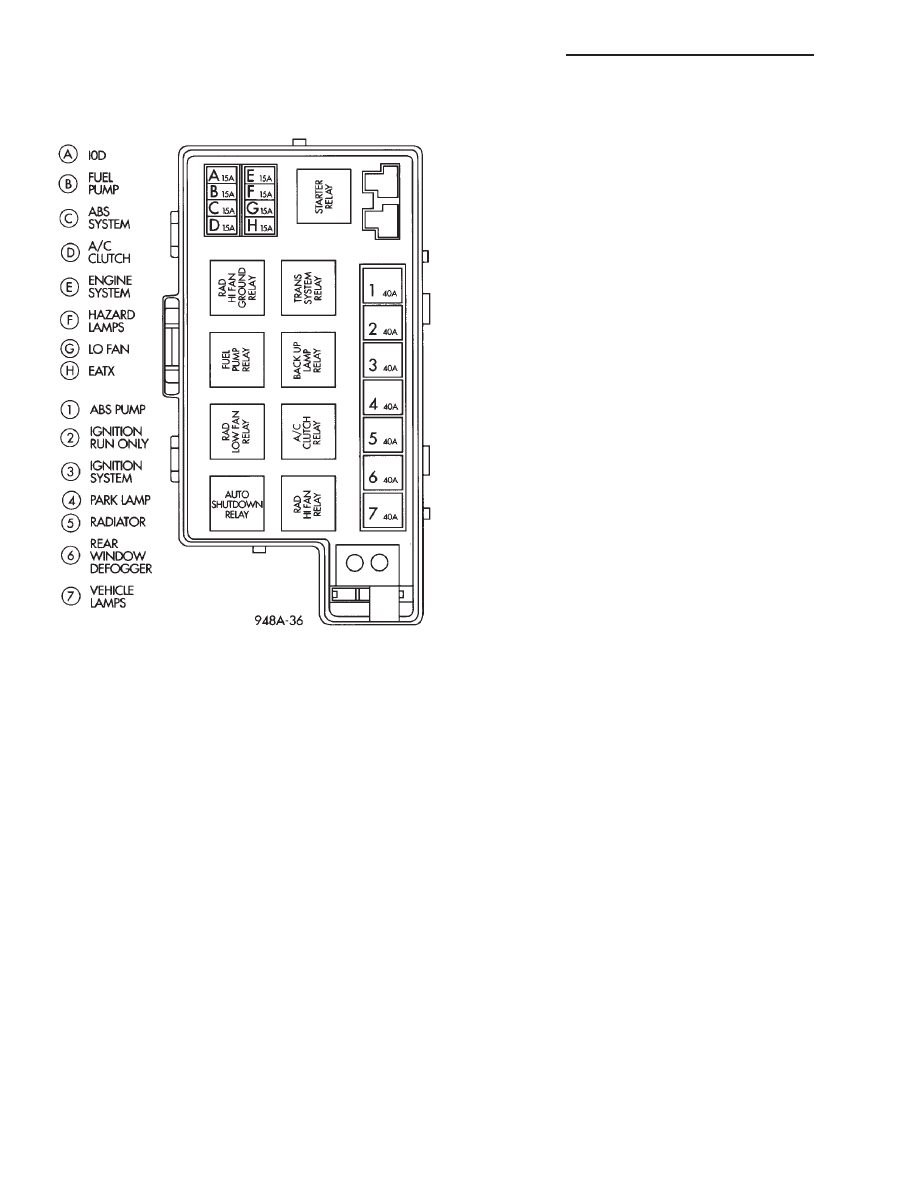
hicle is not used over an extended period of approximately
20 days the IOD fuse in the power distribution center (Fig.
6) should be disconnected. When the vehicle is not going to
be use for 75 days or more disconnect battery negative ca-
ble and isolate.
ABNORMAL BATTERY DISCHARGING
(1) Corroded battery posts, cables or terminals.
(2) Loose or worn generator drive belt.
(3) Electrical loads that exceed the output of the
charging system due to equipment or accessories in-
stalled after delivery.
(4) Slow driving speeds in heavy traffic conditions
or prolonged idling with high-amperage electrical
systems in use.
(5) Defective electrical circuit or component caus-
ing excess Ignition Off Draw (IOD). Refer to Ignition
Off Draw (IOD).
(6) Defective charging system.
(7) Defective battery.
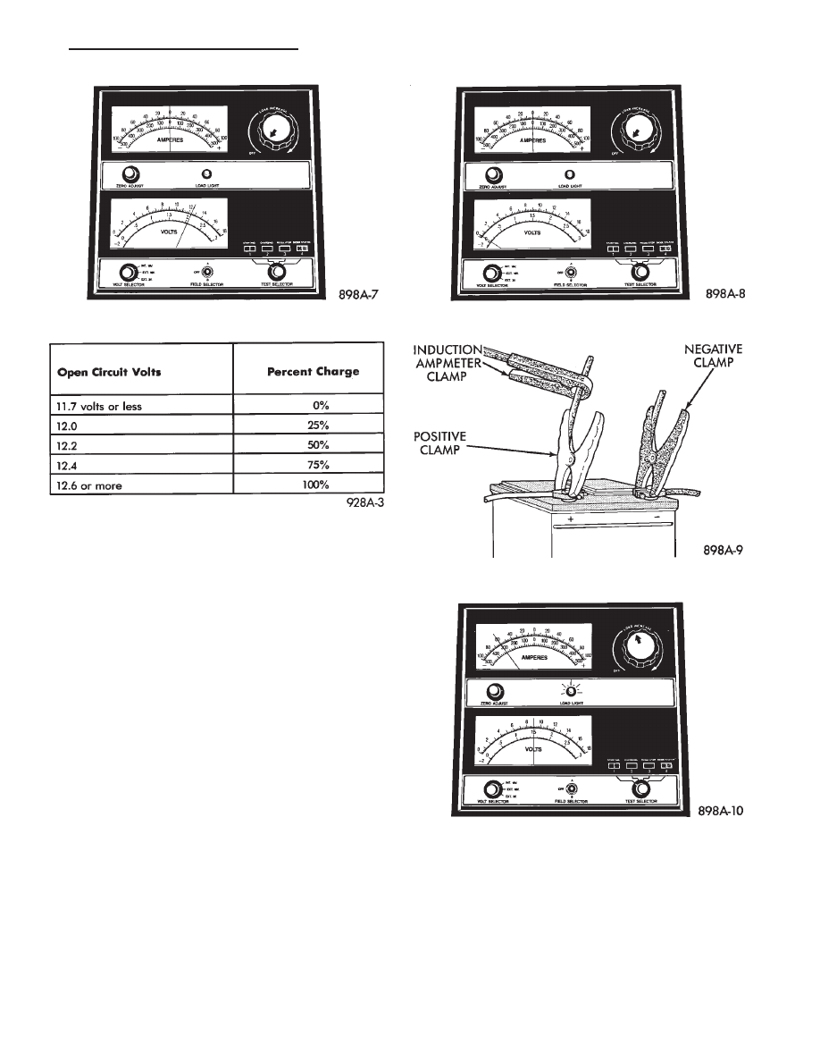
BATTERY OPEN CIRCUIT VOLTAGE TEST
An open circuit voltage no load test shows the state
of charge of a battery. Also, if it will pass a load test
of 50 percent of the battery cold crank rating. Refer
to Battery Load Test. If a battery has an open circuit
voltage reading of 12.4 volts or greater, and will not
endure a load test, it is defective and replacement
would be required. To test open circuit voltage, per-
form the following operation:
(1) Remove both battery cables, negative cable
first. If the battery has been boosted, charged, or
loaded just prior to this operation, allow the battery
a few minutes to stabilize.
(2) Using a voltmeter connected to the battery
posts and measure the open circuit voltage (Fig. 7).
This voltage reading will show the state of charge
of the battery. It will not reveal battery cranking ca-
pacity (Fig. 8).
Fig. 6 IOD Fuse
8A - 4
BATTERY/STARTING/CHARGING SYSTEMS DIAGNOSTICS
.
BATTERY LOAD TEST
A fully charged battery must have reserve cranking
capacity. This will enable the starter motor and igni-
tion system enough power to start the engine over a
broad range of ambient temperatures. A battery load
test will verify the actual cranking performance
based on the cold crank rating of the battery.
WARNING: IF BATTERY SHOWS SIGNS OF FREEZ-
ING, LEAKING, LOOSE POSTS, OR EXCESSIVELY
LOW ELECTROLYTE LEVEL, DO NOT TEST. ACID
BURNS OR AN EXPLOSIVE CONDITION MAY RE-
SULT.
(1) Remove both battery cables, NEGATIVE cable
first. Battery top, cables and posts should be clean. If
green dot is not visible in indicator, charge the bat-
tery. Refer to Battery Charging Procedures.
(2) Use a suitable Volt/Ammeter/Load tester (Fig.
9) connected to the battery posts (Fig. 10). Check the
open circuit voltage of the battery. Voltage should be
equal to or greater than 12.4 volts with the green dot
visible in test indicator.
(3) Rotate the load control knob of the Carbon pile
rheostat to apply a 300 amp load. Apply this load for
15 seconds to remove the surface charge from the
battery, and return the control knob to off (Fig. 11).
(4) Allow the battery to stabilize for 15 seconds,
and then verify open circuit voltage.
(5) Rotate the load control knob on the tester to
maintain 50% of the battery cold crank rating for a
minimum 15 seconds (Fig. 12).
After 15 seconds, record the loaded voltage reading
and return the load control to off.
(6) Voltage drop will vary according to battery tem-
perature at the time of the load test. Battery temper-
ature can be estimated by the temperature of
exposure over the preceding several hours. If the bat-
Fig. 8 Battery Open Circuit Voltage
Fig. 7 Testing Open Circuit Voltage
Fig. 9 Volt-Ammeter-Load Tester
Fig. 10 Volt-Ammeter-Load Tester Connections
Fig. 11 Remove Surface Charge from Battery
.
BATTERY/STARTING/CHARGING SYSTEMS DIAGNOSTICS
8A - 5
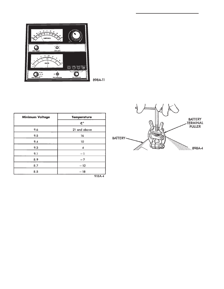
tery has been charged, boosted, or loaded a few min-
utes prior to the test, the battery would be slightly
warmer. Refer to Fig. 13 for proper loaded voltage
reading.
(7) If battery passes load test, it is in good condi-
tion and further tests are not necessary. If it fails
load test, it should be replaced.
BATTERY CHARGING
A battery is considered fully charged when it will
meet all the following requirements:
• It has an open circuit voltage charge of at least
12.4 volts (Fig. 8).
• It passes the 15 second load test (Fig. 13).
• The built in test indicator dot is GREEN (Fig. 5).
The battery cannot be refilled with water, it must
be replaced.
WARNING: DO NOT CHARGE A BATTERY THAT
HAS EXCESSIVELY LOW ELECTROLYTE LEVEL.
BATTERY
MAY
SPARK
INTERNALLY
AND
EX-
PLODE.
EXPLOSIVE GASES FORM OVER THE BATTERY.
DO
NOT
SMOKE,
USE
FLAME,
OR
CREATE
SPARKS NEAR BATTERY.
DO NOT ASSIST BOOST OR CHARGE A FROZEN
BATTERY. BATTERY CASING MAY FRACTURE.
BATTERY ACID IS POISON, AND MAY CAUSE SE-
VERE BURNS. BATTERIES CONTAIN SULFURIC
ACID. AVOID CONTACT WITH SKIN, EYES, OR
CLOTHING. IN THE EVENT OF CONTACT, FLUSH
WITH WATER AND CALL PHYSICIAN IMMEDIATELY.
KEEP OUT OF REACH OF CHILDREN.
CAUTION: Disconnect the battery NEGATIVE cable
first (Fig. 14) before charging battery to avoid dam-
age to electrical systems. Do not exceed 16.0 volts
while charging battery. Refer to the instructions
supplied with charging equipment
Battery electrolyte will bubble inside of battery
case while being charged properly. If the electrolyte
boils violently, or is discharged from the vent holes
while charging, immediately reduce charging rate or
turn off charger. Evaluate battery condition. Battery
damage may occur if charging is excessive.
Some battery chargers are equipped with polarity
sensing devices to protect the charger or battery from
being damaged if improperly connected. If the bat-
tery state of charge is too low for the polarity sensor
to detect, the sensor must be bypassed for charger to
operate. Refer to operating instructions provided
with battery charger being used.
CAUTION: Charge battery until test indicator ap-
pears green. Do not overcharge.
It may be necessary to jiggle the battery or vehicle
to bring the green dot in the test indicator into view.
After the battery has been charged to 12.4 volts or
greater, perform a load test to determine cranking
capacity. Refer to BATTERY LOAD TEST in this
Group. If the battery will endure a load test, return
the battery to use. If battery will not endure a load
test, it must be replaced. Properly clean and inspect
battery hold downs, tray, terminals, cables, posts,
Fig. 12 Load 50% Cold Crank Rating
Fig. 13 Load Test Temperature
Fig. 14 Disconnect Battery Negative Cable
8A - 6
BATTERY/STARTING/CHARGING SYSTEMS DIAGNOSTICS
.
and top before completing service. Also refer to
Group 8B, Battery/Starter/Generator Service.
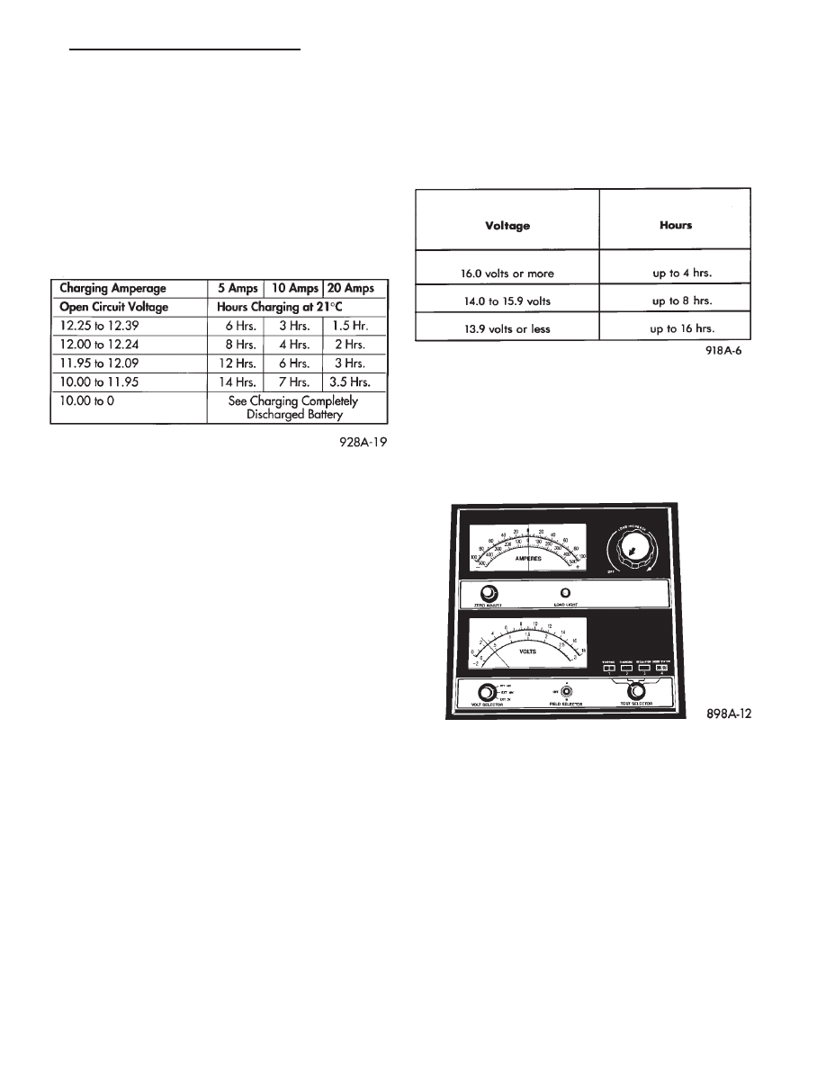
CHARGING TIME REQUIRED
The time required to charge a battery will vary de-
pending upon the following factors:
• SIZE OF BATTERY
A completely discharged of a large heavy-duty bat-
tery requires more than twice the recharging time as
a completely discharged small capacity battery (Fig.
15).
• TEMPERATURE
A longer time will be needed to charge a battery at
-18°C (0°F) than at 27°C (80°F). When a fast charger
is connected to a cold battery, current accepted by
battery will be very low at first. In time, the battery
will accept a higher rate as battery warms.
• CHARGER CAPACITY
A charger which can supply only five amperes will
require a much longer period of charging than a
charger that can supply 30 amperes or more.
• STATE OF CHARGE
A completely discharged battery requires more
charging time than a partially charged battery. Elec-
trolyte is nearly pure water in a completely dis-
charged
battery. At
first,
the
charging
current
amperage will be low. As water is converted to sulfu-
ric acid inside the battery, the current amp rate will
rise. Also, the specific gravity of the electrolyte will
rise, bringing the green dot (Fig. 5) into view.
WARNING:
NEVER
EXCEED
20
AMPS
WHEN
CHARGING A COLD -1°C (30°F) BATTERY. PER-
SONAL INJURY MAY RESULT.
CHARGING COMPLETELY DISCHARGED
BATTERY
The following procedure should be used to recharge
a completely discharged battery. Unless procedure is
properly followed, a good battery may be needlessly
replaced (Fig. 16).
(1) Measure the voltage at battery posts with a
voltmeter accurate to 1/10 volt (Fig. 17). If below 10
volts, charge current will be low, and it could take
some time before it accepts a current in excess of a
few milliamperes. Such low current may not be de-
tectable on amp meters built into many chargers.
(2) Connect charger leads. Some chargers feature
polarity protection circuitry that prevents operation
unless charger is connected to battery posts correctly.
A completely discharged battery may not have
enough voltage to activate this circuitry. This may
happen though the leads are connected properly.
(3) Battery chargers vary in the amount of voltage
and current they provide. For the time required for
the battery to accept measurable charger current at
various voltages, refer to Fig. 16. If charge current is
still not measurable after charging times, the battery
should be replaced. If charge current is measurable
during charging time, the battery may be good, and
charging should be completed in the normal manner.
Fig. 15 BATTERY CHARGING TIME
Fig. 16 CHARGE RATE
Fig. 17 Voltmeter Accurate to 1/10 Volt (Connected)
.
BATTERY/STARTING/CHARGING SYSTEMS DIAGNOSTICS
8A - 7
IGNITION OFF DRAW (IOD)
GENERAL INFORMATION
A normal electrical system will draw from 5 to 30
milliamperes from the battery. This is with the igni-
tion in the OFF position, and all non-ignition con-
trolled circuits in proper working order. The amount
of IOD will depend on body model and electrical com-
ponents. A vehicle that has not been operated for an
extended period approximately 20 days may dis-
charge the battery to an inadequate level. In this
case, the IOD fuse should be disconnected. The IOD
fuse is located in the power distribution center.
If the IOD is over 30 milliamperes, the defect must
be found and corrected before replacing the battery.
Usually, the battery can be charged and returned to
service (Fig. 15).
IGNITION OFF DRAW (IOD) TESTS
VEHICLES WITHOUT ELECTRONIC AUTOMATIC
TRANSMISSION
Testing for HIGHER AMPERAGE IOD must be
performed first to prevent damage to most milliamp
meters.
A standard 12 volt test light and a milliamp meter
that is equipped with two leads must be used for the
following tests. The milliamp meter should be able to
handle up to two amps.
(1) Verify that all electrical accessories are OFF.
Turn off all lights, close trunk lid, close glove box
door, turn off sun visor vanity lights, close all doors
and remove ignition key. Allow the Illuminated Entry
System if equipped to time out in approximately 30
seconds.
(2) Verify the engine compartment lamp is working
by opening/closing hood. Remove the lamp.
(3) Disconnect battery negative cable (Fig. 14).
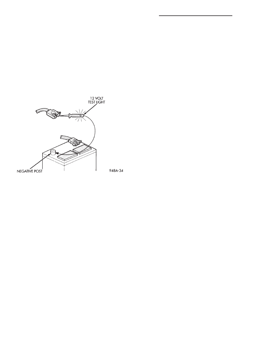
(4) Connect a typical 12-volt test light low wattage
lamp between the negative cable clamp and the bat-
tery negative post (Fig. 18). The test light may be
brightly lit for three minutes or may not be lit at all.
(a) The term brightly used throughout the fol-
lowing tests. This implies the brightness of the test
light will be the same as if it were connected across
the battery posts. This would be with a fully
charged battery.
(b) The test light or the milliamp meter MUST
be positively connected to the battery post and the
battery cable during all IOD testing.
(c) Do not allow the test light or the milliamp
meter to become disconnected during any of the
IOD tests. If this happens, the electronic timer
functions will be activated and all IOD tests must
be repeated from the beginning. Clamp the test
light at both ends to prevent accidental disconnec-
tion.
(d) After three minutes time has elapsed, the
test light should turn off or be dimly lit. This will
depending on the electronic components on the ve-
hicle. If the test light remains brightly lit, do not
disconnect test light. Disconnect each fuse or cir-
cuit breaker (refer to Group 8W, Wiring Diagrams)
until test light is either off or dimly lit. This will
identify the high amperage IOD circuit. Repair cir-
cuit as necessary. It is now safe to install milliamp
meter to check for low amperage IOD.
(e) Possible sources of high IOD are usually ve-
hicle trunk lamp, glove compartment, luggage com-
partment and etc..
(f) If test light is still BRIGHTLY lit after discon-
necting each fuse and circuit breaker, disconnect
the wiring harness from the generator. Refer to
Generator Testing. Do not disconnect test light.
CAUTION: The last test has higher amperage IOD
must be performed before proceeding with low am-
perage IOD tests. The higher amperage IOD must
be eliminated before hooking up milliamp meter to
check for low amperage IOD. If higher amperage
IOD has not been eliminated, milliamp meter may
be damaged. Most milliamp meters will not handle
over one or two amps. Do not hook up meter if test
light is glowing brightly. Refer to maximum amper-
age specifications and instructions supplied with
milliamp meter.
After higher amperage IOD has been corrected, low
amperage IOD may be checked. The MAXIMUM IOD
= 30 MILLIAMPERES.
(5) With test light still connected, connect milliamp
meter between battery negative post and battery
Fig. 18 IOD Test
8A - 8
BATTERY/STARTING/CHARGING SYSTEMS DIAGNOSTICS
.
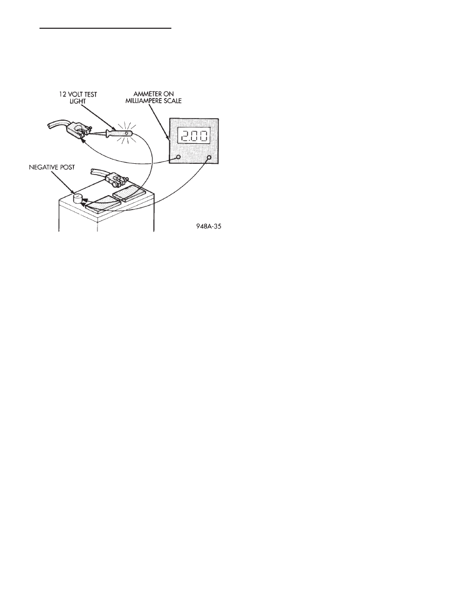
negative cable (Fig. 19). Do not open any doors or
turn on any electrical accessories with the test light
disconnected and the milliamp meter connected.
Meter may be damaged.
(6) Disconnect test light. Milliamp meter reading
should be less than 30 milliamperes. If low amperage
IOD is not within specifications, disconnect:
(a) The 60 way connector at the powertrain con-
trol module located outboard of the battery. Refer
to Group 8D, Ignition, for more information.
(b) The 25 way connectors on the body control
module computer.
(c) The circuits to the clock and radio.
(d) The wiring harness from the generator. Refer
to Generator Testing in this Group.
Check each component until excessive IOD is
found.
Each time the test light or milliamp meter is dis-
connected and connected, all electronic timer func-
tions will be activated. Tests must be repeated from
the beginning.
Test light or meter MUST remain connected for all
tests.
VEHICLES WITH ELECTRONIC AUTOMATIC TRANSMISSION
This vehicle will have temporary high IOD of 50
milliamp or more for up to 25 minutes. This higher
IOD can often mask another problem and should be
considered when performing IOD testing.
If high or low IOD is suspected, allow an additional
25 minutes (minimum) of electronic shut off time.
To defeat the timer, disconnect the 60-way connec-
tor on the transmission control module. This com-
puter is located behind the right front strut tower.
Fig. 19 Low Amperage IOD Test
.
BATTERY/STARTING/CHARGING SYSTEMS DIAGNOSTICS
8A - 9
STARTER TEST PROCEDURES ON VEHICLE
INDEX
page
page
Diagnostic Preparation
. . . . . . . . . . . . . . . . . . . . . 10
General Information
. . . . . . . . . . . . . . . . . . . . . . . 10
Starter Control Circuit Tests . . . . . . . . . . . . . . . . . . 13
Starter Feed Circuit Resistance Test
. . . . . . . . . . . 12
Starter Feed Circuit Tests
. . . . . . . . . . . . . . . . . . . 10
GENERAL INFORMATION
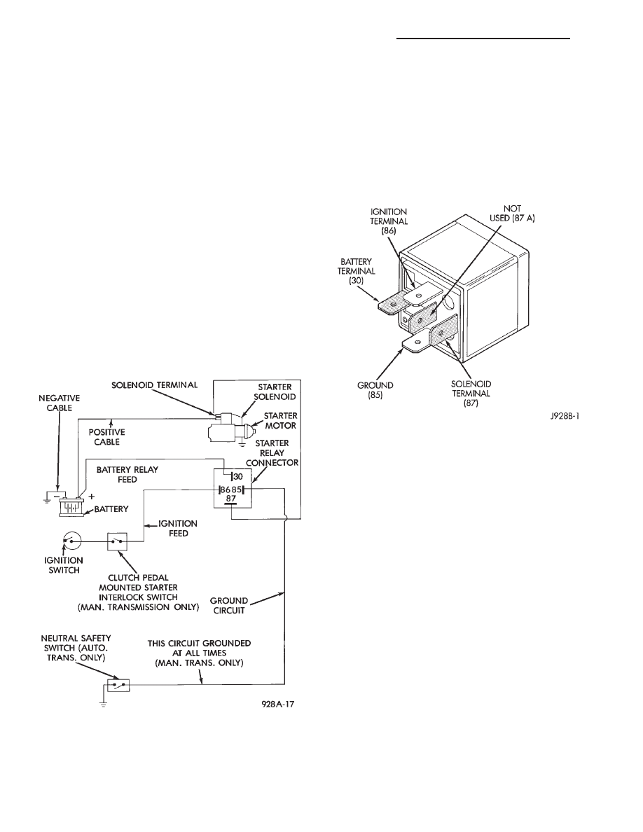
The starting system (Fig. 1) has:
• Ignition switch
• Starter relay (Fig. 2)
• Neutral starting and back-up switch with auto-
matic transmissions only
• Wiring harness
• Battery
• Starter motor with an integral solenoid
These components form two separate circuits. A
high amperage circuit that feeds the starter motor up
to 300+ amps, and a control circuit that operates on
less than 20 amps.
DIAGNOSTIC PREPARATION
Before proceeding with starting system diagnostics,
verify:
(1) The battery top, posts, and terminals are clean.
(2) The generator drive belt tension and condition
is correct.
(3) The battery state-of-charge is correct.
(4) The battery will endure load test.
(5) The battery cable connections at the starter
and engine block are clean and free from corrosion.
(6) The wiring harness connectors and terminals
are clean and free from corrosion.
(7) Proper circuit grounding.
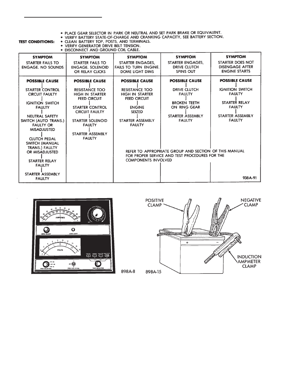
(8) Refer to Starter System Diagnostics (Fig. 3).
STARTER FEED CIRCUIT TESTS
The following procedure will require a suitable
volt-ampere tester (Fig. 4).
CAUTION: Ignition system also must be disabled to
prevent engine start while performing the following
tests.
(1) Connect a volt-ampere tester (Fig. 4) to the bat-
tery terminals (Fig. 5). Refer to the operating in-
structions provided with the tester being used.
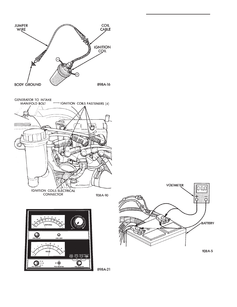
(2) Disable ignition system as follows:
• VEHICLES WITH CONVENTIONAL DISTRIBU-
TORS: Disconnect the ignition coil cable from the dis-
Fig. 1 Starting System Components/Wiring
Fig. 2 Starter Relay
8A - 10
BATTERY/STARTING/CHARGING SYSTEMS DIAGNOSTICS
.
tributor cap. Connect a suitable jumper wire between
the coil cable end-terminal and a good body ground
(Fig. 6).
• VEHICLES WITH DIRECT IGNITION SYSTEM:
Disconnect the ignition coils electrical connector (Fig.
7).
(3) Verify that all lights and accessories are OFF,
and the transmission shift selector is in the PARK.
Set parking brake.
(4) Rotate and hold the ignition switch in the
START position. Observe the volt-ampere tester (Fig.
8).
• If voltage reads above 9.6 volts, and amperage
draw reads above 250 amps, go to the starter feed
circuit resistance test.
• If voltage reads 12.4 volts or greater and amperage
reads 0 to 10 amps, go to starter control circuit test.
CAUTION: Do not overheat the starter motor or
draw the battery voltage below 9.6 volts during
cranking operations.
Fig. 3 Starter System Diagnostics
Fig. 4 Volt Ampere Tester
Fig. 5 Volt-Ampere Tester Connections
.
BATTERY/STARTING/CHARGING SYSTEMS DIAGNOSTICS
8A - 11
(5) After the starting system problems have been
corrected, verify the battery state-of-charge and
charge battery if necessary. Disconnect all testing
equipment and connect ignition coil cable or ignition
coil connector. Start the vehicle several times to as-
sure the problem has been corrected.
STARTER FEED CIRCUIT RESISTANCE TEST
Before proceeding with this operation, review Diag-
nostic Preparation and Starter Feed Circuit Tests.
The following operation will require a voltmeter, ac-
curate to 1/10 of a volt.
CAUTION: Ignition system also must be disabled to
prevent engine start while performing the following
tests.
(1) Disable ignition system as follows:
• VEHICLES WITH CONVENTIONAL DISTRIBU-
TORS
Disconnect the ignition coil cable from the distrib-
utor cap. Connect a suitable jumper wire between the
coil cable end-terminal and a good body ground (Fig.
6).
• VEHICLES WITH DIRECT IGNITION SYSTEM:
Disconnect the ignition coils electrical connector (Fig.
7).
(2) With all wiring harnesses and components
properly connected, perform the following:
(a) Connect the negative lead of the voltmeter to
the battery negative post, and positive lead to the
battery negative cable clamp (Fig. 9). Rotate and
hold the ignition switch in the START position. Ob-
serve the voltmeter. If voltage is detected, correct
poor contact between cable clamp and post.
(b) Connect positive lead of the voltmeter to the
battery positive post, and negative lead to the bat-
tery positive cable clamp. Rotate and hold the igni-
tion switch key in the START position. Observe the
voltmeter. If voltage is detected, correct poor con-
tact between the cable clamp and post.
Fig. 6 Ground Ignition Coil Cable
Fig. 7 Ignition Coils Electrical Connection
Fig. 8 Starter Draw Tests
Fig. 9 Test Battery Connection Resistance
8A - 12
BATTERY/STARTING/CHARGING SYSTEMS DIAGNOSTICS
.
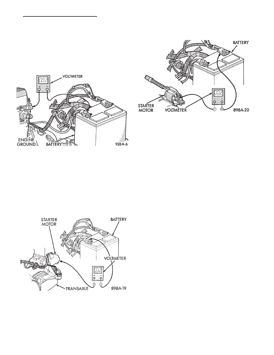
(c) Connect negative lead of voltmeter to battery
negative terminal, and positive lead to engine block
near the battery cable attaching point (Fig. 10). Ro-
tate and hold the ignition switch in the START po-
sition. If voltage reads above 0.2 volt, correct poor
contact at ground cable attaching point. If voltage
reading is still above 0.2 volt after correcting poor
contacts, replace ground cable.
(3) Remove starter heat shield. Refer to Group 8B,
Starter Replacement to gain access to the starter mo-
tor and solenoid connections. Perform the following
steps:
(a) Connect positive voltmeter lead to the starter
motor housing and the negative lead to the battery
negative terminal (Fig. 11). Hold the ignition
switch key in the START position. If voltage reads
above 0.2 volt, correct poor starter to engine
ground.
(b) Connect the positive voltmeter lead to the
battery positive terminal, and negative lead to bat-
tery cable terminal on starter solenoid (Fig. 12).
Rotate and hold the ignition switch in the START
position. If voltage reads above 0.2 volt, correct
poor contact at battery cable to solenoid connection.
If reading is still above 0.2 volt after correcting
poor contacts, replace battery positive cable.
(c) If resistance tests do not detect feed circuit
failures, remove the starter motor and go to Bench
Testing Starter Solenoid in this Group.
STARTER CONTROL CIRCUIT TESTS
The starter control circuit has:
• Starter solenoid
• Starter relay (Fig. 2)
• Neutral starting and back-up switch with auto-
matic transmissions
• Ignition switch
• Battery
• All related wiring and connections
CAUTION: Before performing any starter tests, the
ignition system must be disabled.
VEHICLES
EQUIPPED
WITH
A
CONVEN-
TIONAL DISTRIBUTOR: Disconnect coil wire from
distributor cap center tower. Secure wire to a good
ground to prevent engine from starting (Fig. 6).
• VEHICLES EQUIPPED WITH DIRECT IGNI-
TION SYSTEM: Unplug the coils electrical connector
(Fig. 7).
STARTER SOLENOID TEST
WARNING: CHECK TO ENSURE THAT THE TRANS-
MISSION IS IN THE PARK POSITION WITH THE
PARKING BRAKE APPLIED
(1) Verify battery condition. Battery must be in
good condition with a full charge before performing
any starter tests. Refer to Battery Tests.
(2) Perform this starter solenoid test BEFORE per-
forming the starter relay test.
(3) Raise the vehicle.
(4) Perform a visual inspection of the starter/start-
er solenoid for corrosion, loose connections or faulty
wiring.
Fig. 10 Test Ground Circuit Resistance
Fig. 11 Test Starter Motor Ground
Fig. 12 Test Battery Positive Cable Resistance
.
BATTERY/STARTING/CHARGING SYSTEMS DIAGNOSTICS
8A - 13
(5) Lower the vehicle.
(6) Locate the starter relay (Fig. 13).
(7) Remove the starter relay from the connector.
(8) Connect a remote starter switch or a jumper
wire between the battery positive post and terminal
87 on the starter relay connector. To determine the
starter relay terminal numbers, refer to Fig. 14.
• If engine cranks, starter/starter solenoid is good.
Go to the Starter Relay Test.
• If engine does not or solenoid chatters, check wir-
ing and connectors from starter relay to starter sole-
noid for loose or corroded connections. Particularly at
starter terminals.
• Repeat test. If engine still fails to crank properly,
trouble is within starter or starter mounted solenoid,
and it must be removed for repairs. Refer to Group
8B, Battery/Starter/Generator Service, for Starter
Replacement.
STARTER RELAY TEST
WARNING: CHECK TO ENSURE THAT THE TRANS-
MISSION IS IN THE PARK POSITION WITH THE
PARKING BRAKE APPLIED
(1) Verify battery condition. Battery must be in
good condition with a full charge before performing
any starter tests. Refer to Battery Tests.
(2) Perform the preceding starter solenoid tests
BEFORE performing starter relay tests. Refer to
Starter Solenoid Test.
(3) Locate and remove the starter relay (Fig. 13).
(4) After the starter relay has been located and re-
moved, refer to Starter Relay Tests (Fig. 14).
Fig. 13 Starter Relay Location
8A - 14
BATTERY/STARTING/CHARGING SYSTEMS DIAGNOSTICS
.
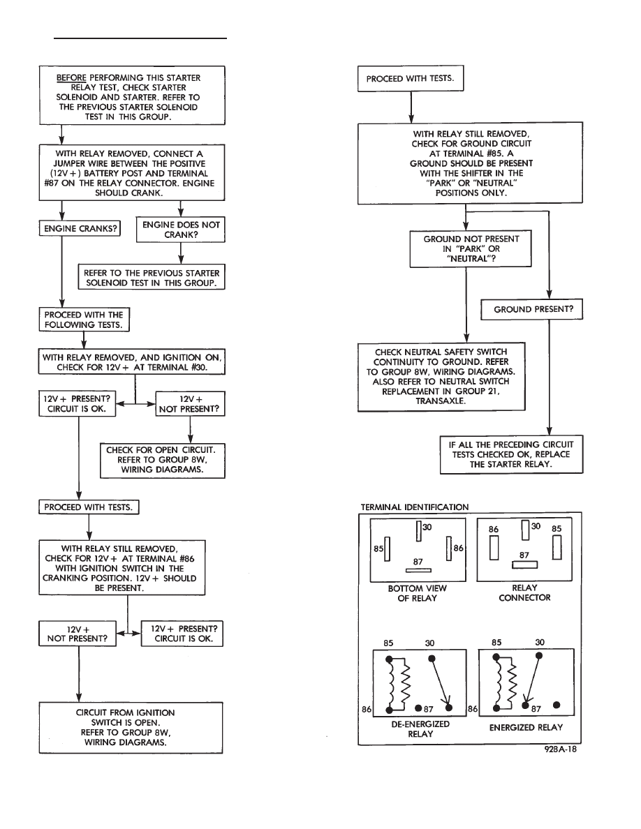
Fig. 14 Starter Relay Tests
.
BATTERY/STARTING/CHARGING SYSTEMS DIAGNOSTICS
8A - 15
NEUTRAL STARTING AND BACK-UP SWITCH
AUTOMATIC TRANSMISSION ONLY
For electrical diagnostics, when checking starter
circuits, refer to Starter Relay Tests (Fig. 14).
For removal and installation of neutral switch, re-
fer to Neutral Starting and Back-up Switch in Group
21, Transaxle.
IGNITION SWITCH TEST
After testing starter solenoid and relay, test igni-
tion switch and wiring. Refer to Group 8D, Ignition
Systems or Group 8W, Wiring Diagrams. Check all
wiring for opens or shorts, and all connectors for be-
ing loose or corroded.
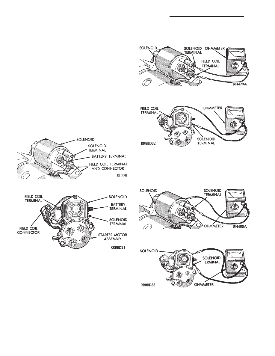
BENCH TESTING STARTER SOLENOID
(1) Disconnect field coil wire from field coil termi-
nal (Figs. 15 or 16).
(2) Check for continuity between solenoid terminal
and field coil terminal with a continuity tester. Con-
tinuity should be detected (Figs. 17 or 18).
(3) Check for continuity between solenoid terminal
and solenoid housing (Figs. 19 or 20). Continuity
should be detected. If continuity is detected, solenoid
is good.
(4) If continuity is not detected in either test, sole-
noid has an open circuit and is defective. Replace the
starter assembly
Fig. 15 Field Coil Wire Terminal—Bosch
Fig. 16 Field Coil Wire Terminal—Nippondenso
Fig. 17 Continuity Test Between Solenoid Terminal
and Field Coil Terminal—Bosch
Fig. 18 Continuity Test Between Solenoid Terminal
and Field Coil Terminal—Nippondenso
Fig. 19 Continuity Test Between Solenoid Terminal
and Solenoid Case —Bosch
Fig. 20 Continuity Test Between Solenoid Terminal
and Solenoid Case —Nippondenso
8A - 16
BATTERY/STARTING/CHARGING SYSTEMS DIAGNOSTICS
.

GENERATOR TEST PROCEDURES ON VEHICLE
INDEX
page
page
Charging System Diagnostics (Fig. 1)
. . . . . . . . . . 17
Current Output Test . . . . . . . . . . . . . . . . . . . . . . . . 17
Output Wire Resistance Test . . . . . . . . . . . . . . . . . 17
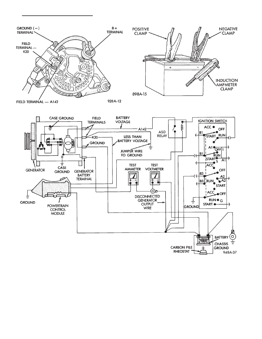
CHARGING SYSTEM DIAGNOSTICS (Fig. 1)
OUTPUT WIRE RESISTANCE TEST
The generator output wire resistance test shows
the amount of voltage drop across the generator out-
put wire between the generator B+ terminal and the
battery positive post.
PREPARATION
Before starting test, make sure the vehicle has a
fully charged battery. Tests and procedures to check
for a fully charged battery are shown in the Battery
section of this Group.
(1) Turn the ignition switch OFF.
(2) Disconnect battery negative cable.
(3) Disconnect the generator B+ output wire from
the generator output battery terminal (Fig. 2).
(4) Connect a 0-150 ampere scale (DC) ammeter in
series between B+ terminal and output wire (Figs. 2
and 3). Connect positive lead to B+ terminal, and
negative lead to output wire.
(5) Using 0-18 volt scale voltmeter, connect the
positive lead to the disconnected (B+) output wire.
Connect the negative lead to battery positive post.
(6) Remove fresh air hose between powertrain con-
trol module and air cleaner if necessary.
(7) Connect jumper wire between a good ground,
and K20 circuit terminal at the back of the genera-
tor.
CAUTION: Do not connect the A142 circuit terminal
(Fig. 1) to ground the Fusible link will burn.
(8) Connect an engine tachometer and connect bat-
tery negative cable.
(9) Connect a volt/amp tester equipped with a vari-
able carbon pile rheostat between battery terminals
(Fig. 4).
Caution: Be sure the carbon pile is in OFF position
before connecting leads.
TEST
(1) Start engine. Immediately after starting, re-
duce engine speed to idle.
(2) Adjust engine speed and carbon pile to main-
tain 20 amperes flowing in the circuit. Observe volt-
meter reading. Voltmeter reading should not exceed
0.5 volts.
RESULTS
If a higher voltage drop is shown, inspect, clean
and tighten all connections between generator B+
terminal and battery positive post. A voltage drop
test may be performed at each connection to locate a
connection with excessive resistance. If resistance
tests are satisfactory, reduce engine speed, turn off
carbon pile, and turn off ignition switch.
(1) Disconnect battery negative cable.
(2) Remove test ammeter, voltmeter, carbon pile,
and tachometer.
(3) Remove jumper wire.
(4) Connect output wire to B+ terminal.
(5) Connect battery negative cable.
(6) Connect fresh air hose between powertrain con-
trol module and air cleaner if removed.
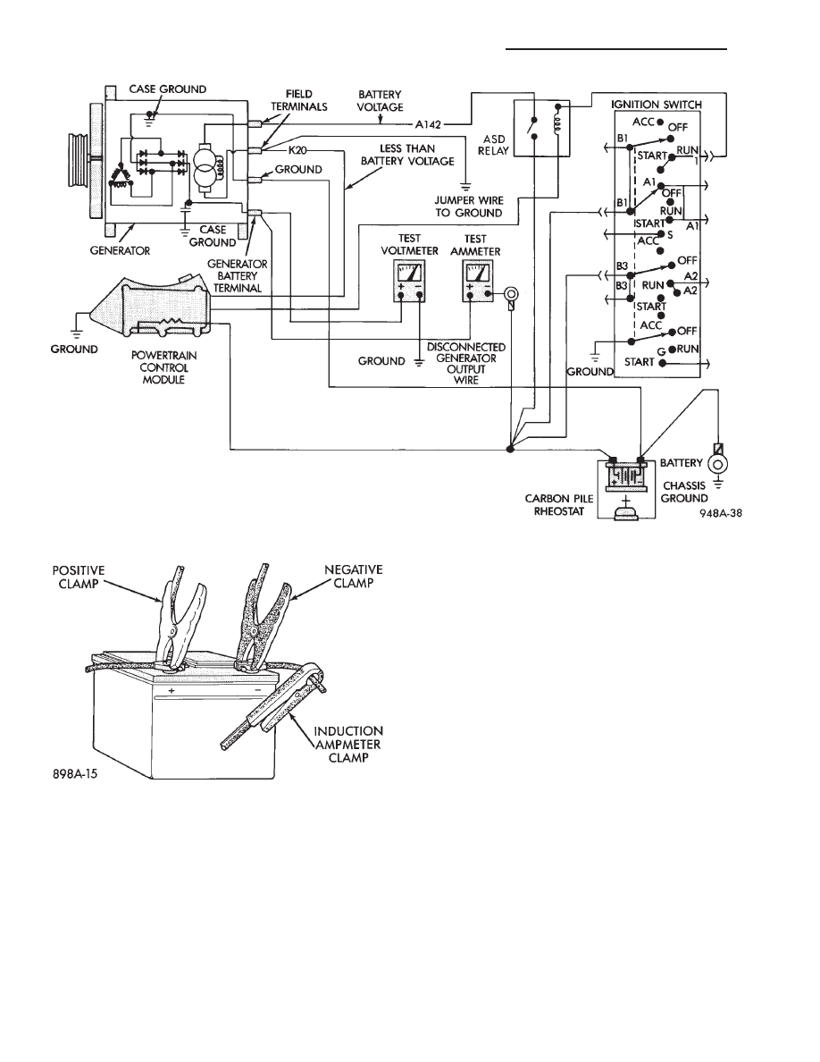
CURRENT OUTPUT TEST
The current output test determines whether or not
the generator is capable of delivering its rated cur-
rent output. For generator identification and output
amperage specifications, refer to Generator Specifica-
tions.
For generator maximum voltage at individual tem-
peratures, refer to Generator Output Voltage Specifi-
cations.
PREPARATION
Before starting any tests, make sure the vehicle
has a fully charged battery. Tests and procedures to
check for a fully charged battery are shown in Bat-
tery section.
(1) Disconnect battery negative cable.
(2) Disconnect output wire at the B+ terminal
(Figs. 2 and 5).
(3) Connect a 0-150 ampere scale (DC) ammeter in
series between the B+ terminal and output wire.
Connect Positive lead to B+ terminal and negative
lead to output wire.
(4) Using 0-18 voltmeter, connect the positive lead
to B+ terminal (Figs. 2 and 4). Connect negative lead
to a good ground.
.
BATTERY/STARTING/CHARGING SYSTEMS DIAGNOSTICS
8A - 17
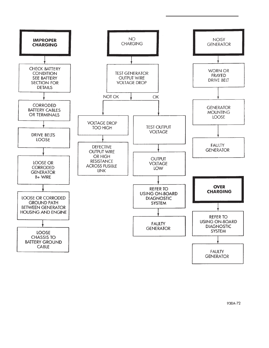
Fig. 1 Charging Diagnostics
8A - 18
BATTERY/STARTING/CHARGING SYSTEMS DIAGNOSTICS
.
(5) Connect an engine tachometer and connect bat-
tery negative cable.
(6) Connect a volt/amp tester equipped with a vari-
able carbon pile rheostat between battery terminals
(Fig. 6). Be sure carbon pile is in OFF position before
connecting leads.
(7) Remove fresh air hose between powertrain con-
trol module and air cleaner if necessary.
(8) Full field the generator. Connect a jumper wire
between a good ground and to the K20 circuit termi-
nal at the back of the generator (Figs. 2 and 5).
CAUTION: Do not connect the A142 circuit terminal
(Fig. 2) to ground the Fusible link will burn.
TEST
(1) Start the engine. Immediately after starting,
reduce engine speed to idle.
Fig. 2 Generator Wiring Connections
Fig. 3 Generator Output Wire Resistance Test
Fig. 4 Volt/Amp Tester Connections
.
BATTERY/STARTING/CHARGING SYSTEMS DIAGNOSTICS
8A - 19
(2) Adjust the carbon pile and engine speed in
steps until an engine speed of 1250 rpm, and a volt-
meter reading of 15 volts is obtained.
CAUTION: Do not allow the battery voltage to ex-
ceed 16 volts.
(3) The generator amperage must meet the output
requirements for the particular generator being
tested. Refer to Generator Specifications for genera-
tor identification and amperage outputs.
RESULTS
(1) If amperage reading is less than specified, and
generator output wire resistance is not found exces-
sive from the previous test, generator should be re-
placed. Refer to Generator replacement in Group 8B,
Battery/Starter/Generator Service. These generators
are not intended to be disassembled for service. It
must be replaced as an assembly.
(2) After current output test is completed, reduce
engine speed, turn off carbon pile, and turn off igni-
tion switch.
(3) Disconnect battery negative cable.
(4) Remove test ammeter, voltmeter, tachometer
and carbon pile.
(5) Remove jumper wire between K20 circuit ter-
minal and ground.
(6) Connect output wire to B+ terminal.
(7) Connect battery negative cable.
(8) Connect fresh air hose between powertrain con-
trol module and air cleaner if removed.
Fig. 5 Generator Current Output Test
Fig. 6 Volt/Amp Tester Connections
8A - 20
BATTERY/STARTING/CHARGING SYSTEMS DIAGNOSTICS
.
DIAGNOSTIC CODES—ON BOARD DIAGNOSTICS
INDEX
page
page
Diagnostic Testing Using Diagnostic Codes
. . . . . . 22
DRB Diagnostic Tester
. . . . . . . . . . . . . . . . . . . . . 25
General Description/Information . . . . . . . . . . . . . . . 21
GENERAL DESCRIPTION/INFORMATION
Another way of diagnosing charging system prob-
lems can be accomplished using the On-Board Diag-
nostic System Codes.
A Diagnostic Code shows a potential problem in a
monitored circuit, or a condition caused by a faulty
component. A Diagnostic Code can be retrieved by
turning the ignition switch ON-OFF-ON-OFF-ON
without starting the engine, and counting the possi-
ble number of flashes of the Malfunction Indicator
(Check Engine) Lamp in the instrument cluster.
EXAMPLES:
• If the Malfunction Indicator (Check Engine) Lamp
flashes four times, pauses, and flashes one more
time, a Code 41 is shown. The first set of four flashes
indicates the number four. The second set of one
flash indicates one.
• If the Malfunction Indicator (Check Engine) Lamp
flashes four times, pauses, and flashes six more
times, a Code 46 is shown. The first set of four
flashes indicates the number four. The second set of
six flashes indicates six.
• If the Malfunction Indicator (Check Engine) Lamp
flashes four times, pauses, and flashes seven more
times, a Code 47 is indicated. The first set of four
flashes indicates the number four. The second set of
seven flashes indicates seven.
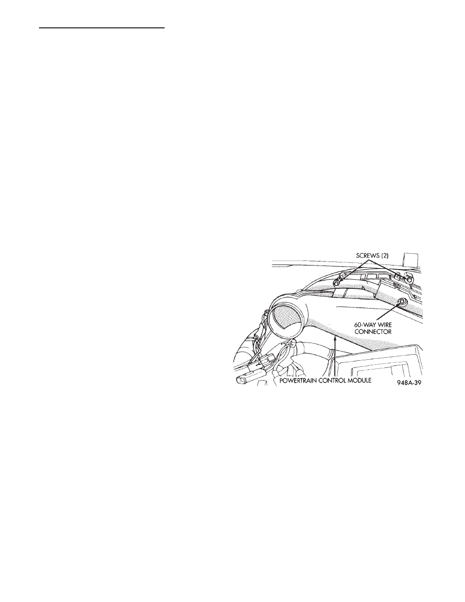
POWERTRAIN CONTROL MODULE
The powertrain control module is equipped with
On-Board Diagnostic features and monitors all en-
gine control circuits during a run/drive period. If a
circuit or system does not perform properly, the pow-
ertrain control module will file in memory a predeter-
mined diagnostic code. This can be used to help in
diagnosing a problem. After 50 to 100 ignition switch
ON/RUN cycles, the memory will be erased if the
code does not reoccur.
The powertrain control module is located in the en-
gine compartment outboard of the battery (Fig. 7).
Fig. 7 Powertrain Control Module
.
BATTERY/STARTING/CHARGING SYSTEMS DIAGNOSTICS
8A - 21
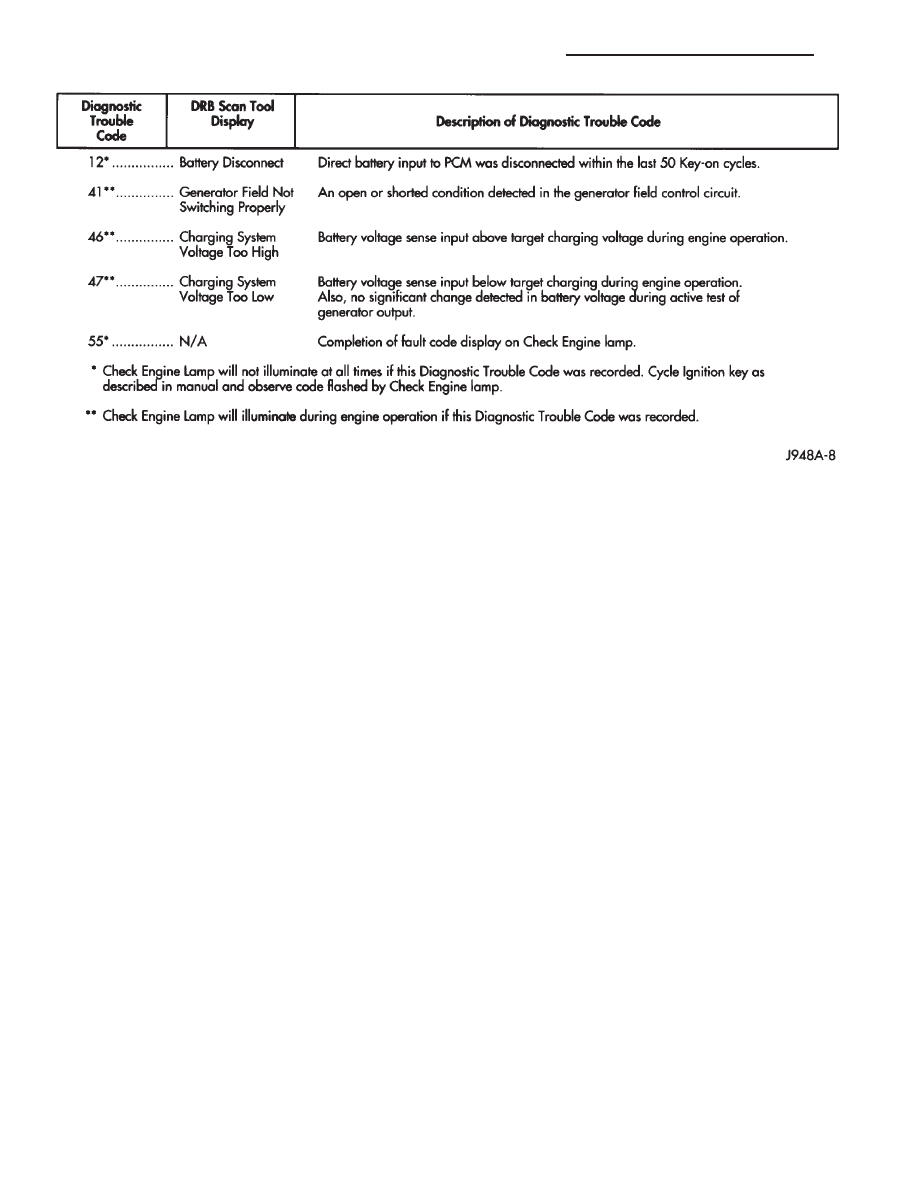
Refer to Fig. 8 Generator Diagnostic Code chart for
relationships of generator/charging system diagnostic
code numbers.
DIAGNOSTIC TESTING USING DIAGNOSTIC CODES
For diagnostic testing when using the diagnostic
codes, refer to Figs. 9 through 13.
Fig. 8 Generator Diagnostic Codes
8A - 22
BATTERY/STARTING/CHARGING SYSTEMS DIAGNOSTICS
.
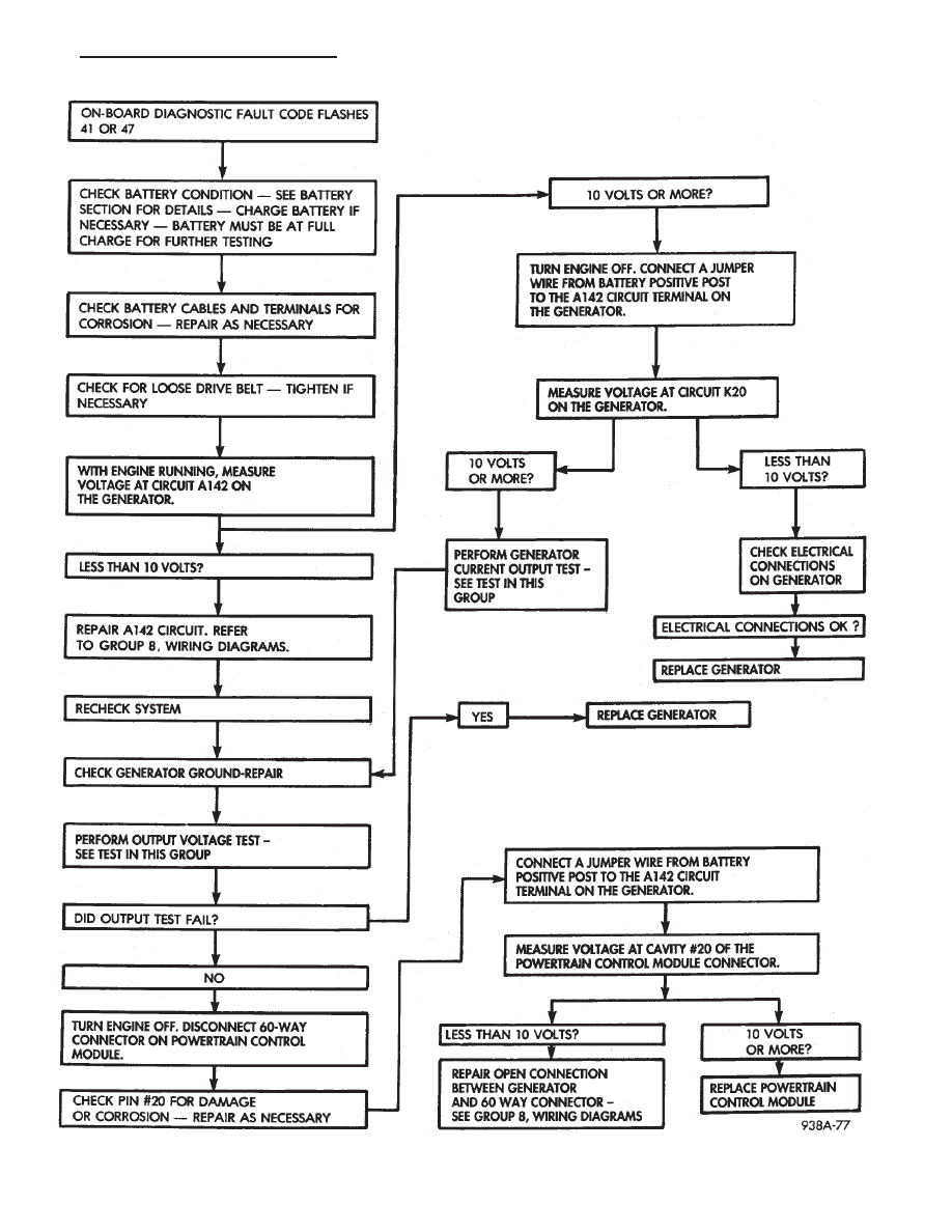
Fig. 9 CHECK FOR INADEQUATE/LOW CHARGING—USING ON BOARD DIAGNOSTIC CODES
.
BATTERY/STARTING/CHARGING SYSTEMS DIAGNOSTICS
8A - 23
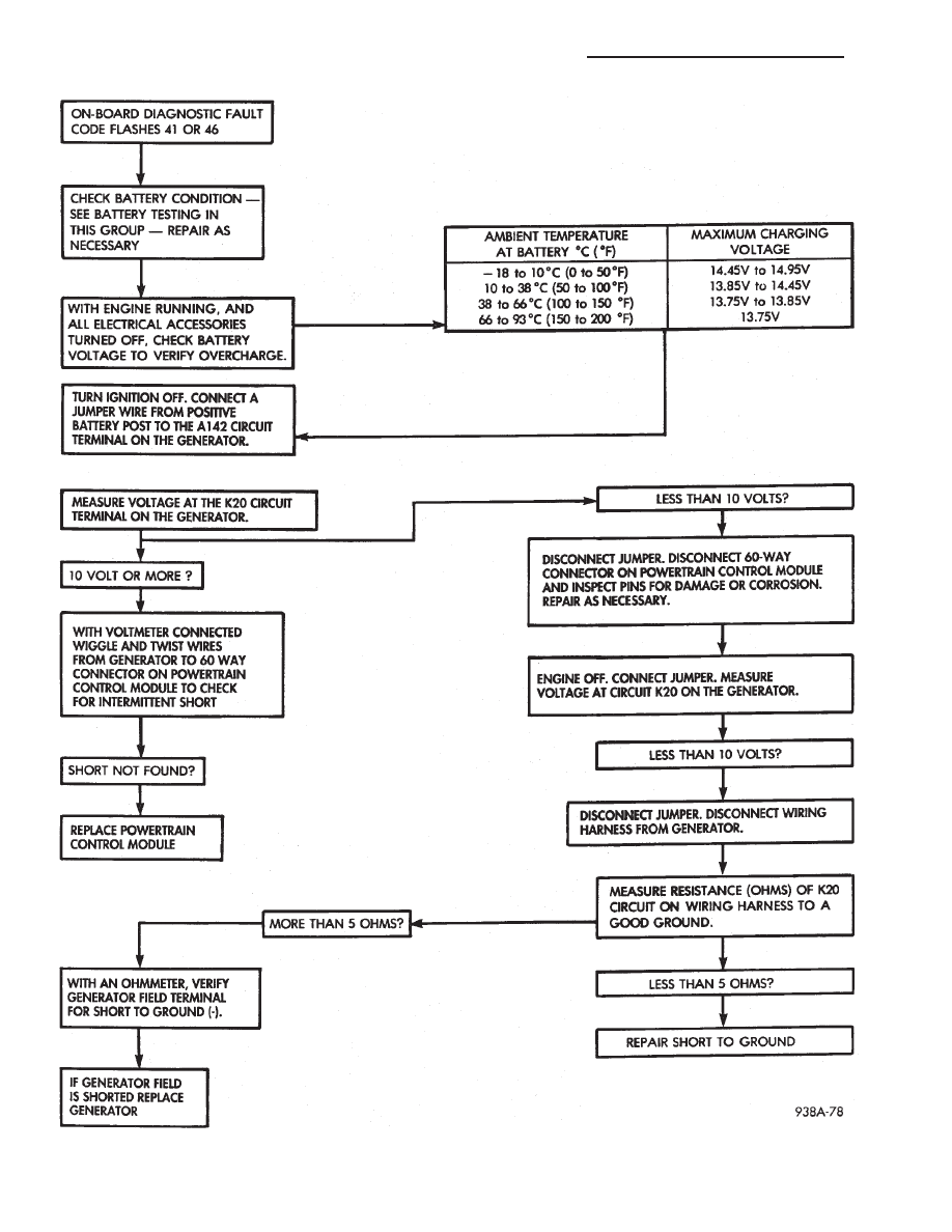
Fig. 10 CHECK FOR OVERCHARGING—USING ON BOARD DIAGNOSTIC CODES
8A - 24
BATTERY/STARTING/CHARGING SYSTEMS DIAGNOSTICS
.
DRB DIAGNOSTIC TESTER
TESTING
A more accurate device to retrieve diagnostic codes
is
Diagnostic
Tool
(DRB).
This
diagnostic
tool,
plugged into the data link connector (Fig. 6) located
near the left shock tower will display code descrip-
tions. The DRB can also test various circuits and
component functions. Refer to the instructions pro-
vided with the DRB tool being used. Descriptions of
Diagnostic Codes for other vehicle systems can be
found in the General Diagnosis section of Group 14,
Fuel System.
SPECIFICATIONS
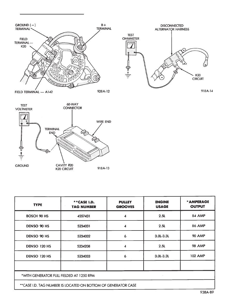
Fig. 11 Generator Wiring Connections
Fig. 12 Powertrain Control Module Connector
Fig. 13 Electrical Resistance Test
GENERATOR AMPERAGE/IDENTIFICATION NUMBERS
.
BATTERY/STARTING/CHARGING SYSTEMS DIAGNOSTICS
8A - 25
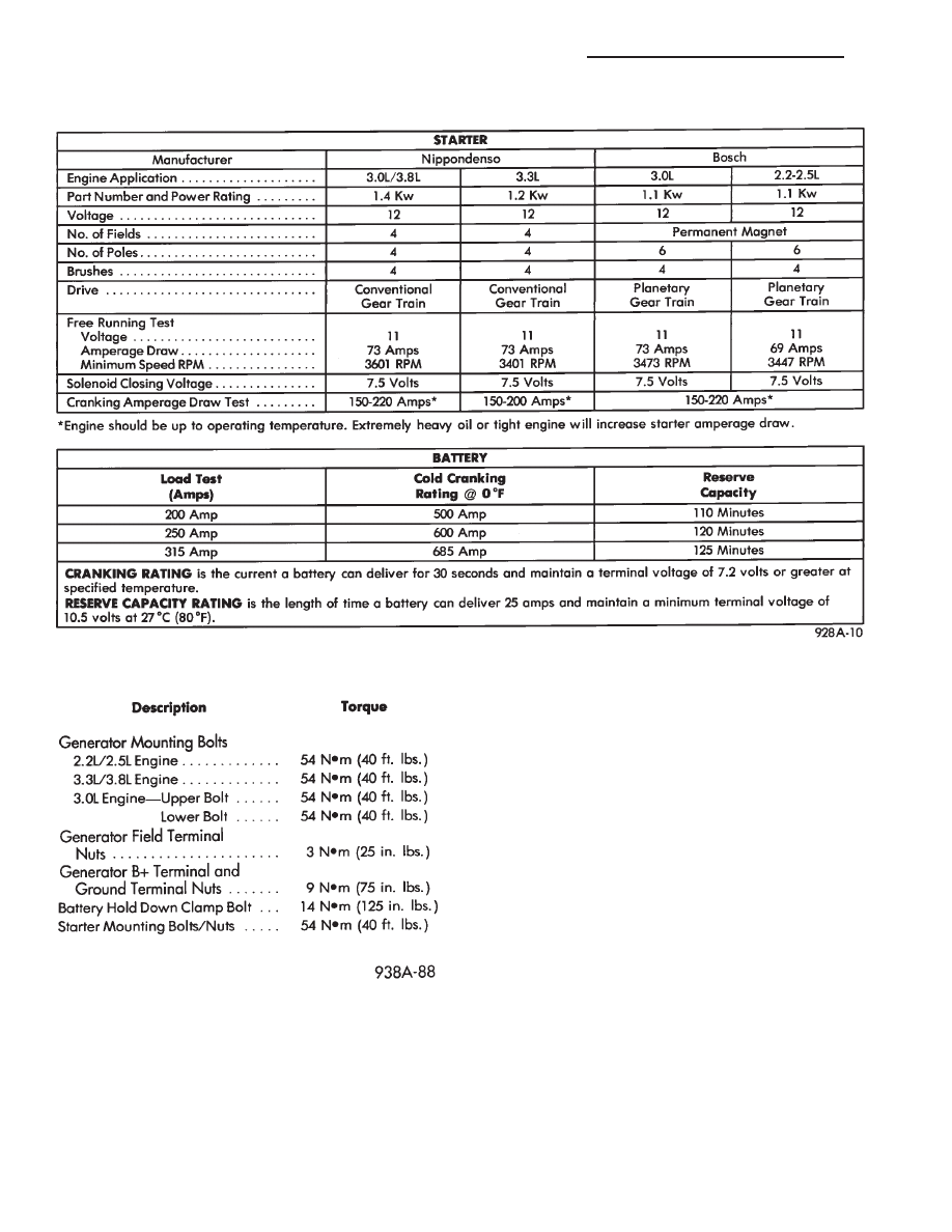
STARTER/BATTERY
TORQUE SPECIFICATIONS
8A - 26
BATTERY/STARTING/CHARGING SYSTEMS DIAGNOSTICS
.
Document Outline
- ELECTRICAL
- BATTERY/ STARTING/ CHARGING SYSTEMS DIAGNOSTICS
Wyszukiwarka
Podobne podstrony:
8a Nadcisnienie leczenie
8a Syntezy prostych aminokwasów
8a
8a
Fizyka 8a
EZG 8A
exam skills test 7&8a
speaking test 7&8a
WYKLAD 8a, GOSPODARKA NIERUCHOMOŚCIAMI - SEM
Wybrane problemy współczesnej administracji i prawa administracyjnego, WYKLAD 8a, Wykład Z 7
deon, 1c 2b 3b 4d 5a 6c 7d 8a 9b 10d 11b 12a 13b 14d 15c 16 b 17b 18d 19c 20b 21d 22d 23a 24a 25a 26
8a
6 4 8a
8a
8A Kurs operatora VHF
Mikro II W 8a Ł
więcej podobnych podstron