Z5
S
P
R
I
N
G
Q
R
2
0
,,,
,,,
,,,
yyy
yyy
yyy
8
9
18
19
20
21
22
23
16
17
7
11
15
14
5
25
1
27
37
6
10
12
13
3
34
35
2
36
26
4
24
28
29
30
31
32

Z5
S
P
R
I
N
G
Q
R
2
0
±
2
178
Ø30
TRA
VEL 100
396.5
(49)
15
348
82
80
110
130
10 10
248.5
22
43
20
26.5
±
2
L.MAX=475.5
L.L.=465.5
L.MIN=365.5
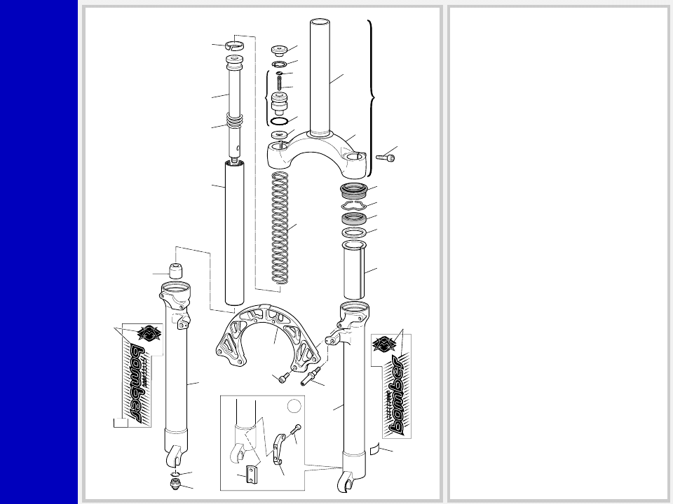
GENERAL
• The fork is sprung by a mechanical coil system and uses
hydraulic rebound damping.
• Spring pre-load adjustment controlled by outer adjuster.
• Stanchions and full length bushings for superior rigidity.
• Parts subjected to friction are cooled and lubricated by a
specially formulated oil.
• Brake caliper adapter available, fits onto LH slider.
Steer Tube: EASTON aluminum steer tubes in non threaded
1 1/8” diameter.
Crown: Forged and CNC-machined BAM
❊
aluminum alloy.
Arch: Forged and CNC-machined BAM
❊
aluminum alloy.
Stanchions: Special chrome-molybdenum steel, hard-chromated.
Sliders: Cast and CNC-machined BAM
❊
aluminum alloy.
Springs: Constant pitch springs.
Slider bushing: Full length guide bushingS composed of a
copper base and impregnated with an anti-friction coating.
Seals: Computer designed oil seals guarantee the highest quality
seals available.
Oil: Specially formulated oil which eliminates foaming and viscos-
ity breakdown while providing complete stiction-free performance.
Fork leg oil: 100 cc type EBH 16 - SAE 7.5.
❊
BAM: Bomber Aerospace Material.
Special alloy developed from aerospace material.

Z5
S
P
R
I
N
G
Q
R
2
0
GENERAL RULES FOR
CORRECT OVERHAULING
AND MAINTENANCE
1. Where specified, assemble and disas-
semble the shock absorption system
using the MARZOCCHI special tools
only.
2. On reassembling the suspension sys-
tem, always use new seals.
3. If two screws are close one to the other,
always tighten using a 1-2-1 sequence.
In short, screw the first screw just up to
the point it is well tightened, then tighten
the second screw and then go back to
the first one and screw it tighter.
4. Clean all metal parts with a special,
preferably biodegradable solvent, such
as trichloroethane or trichloroethylene.
5. Before reassembling, lubricate all parts
in contact with each other using sili-
cone fat spray.
6. Always grease the conic seal rings
before reassembling.
7. Use wrenches with metric size only.
Wrenches with inch size might dam-
age the fastening devices even when
their size is similar to that of the wrenches
in metric size.
INSTRUCTIONS

Z5
S
P
R
I
N
G
Q
R
2
0
FAILURES, CAUSES AND REMEDIES
This paragraph reports some failures that may occur when using the fork. It also indicates possible causes and suggests a remedy. Always
refer to this table before doing any repair work.
Oil leaking through the bottom of slider
O-ring on the pumping rod nut is damaged
Replace the O-ring
Oil leaking though the top of slider
1. Slider oil seal is worn out
2. Stanchion tube is scored
3. Excessive dirt on slider oil seal
1. Replace oil seal
2. Replace crown and stanchions assem-
bly and oil seals
3. Clean the oil seal seat and replace oil
seal
Fork has not been used for some time and
is locked out
Oil seals and dust seals tend to stick to
stanchion tubes
Raise dust seal and lubricate stanchion
tube, dust seal and oil seal
Excessive play of stanchions in the sliders
Pilot bushings are worn
Replace pilot bushings
FAILURES
CAUSES
REMEDIES

Z5
S
P
R
I
N
G
Q
R
2
0
RECOMMENDATIONS
FOR MAINTENANCE
MARZOCCHI forks are based on ad-
vanced technology, supported by year-
long experience in the field of profes-
sional mountain biking. In order to achieve
best results, we recommend to check and
clean the area below the dust seal and the
stanchion tube after each use and lubri-
cate with silicone oil.
INSTALLATION
Installing the Z5 fork on a bicycle is a very
delicate operation that should be carried
out with extreme care.
The installation should always be checked
by one of our Technical Service Centers.
WARNING: Steer tube/headset
mounting and adjustment must be
carried out in compliance with the head-
set manufacturer’s instructions. Improper
installation may jeopardize the safety of
the rider.
To replace it, contact one of our Technical
Service Centers with the required tools.
WARNING: In case of improper
installation of the steer tube into the
crown, the rider could lose control of his/
her bicycle, thus jeopardizing his/her
safety.
WARNING: Brake supports fea-
ture fixing pins or - as an option -
bolts. Never remove these pins (or bolts),
as they help keep brake arch-sliders-as-
sembly locked securely together.
Z5
S
P
R
I
N
G
Q
R
2
0
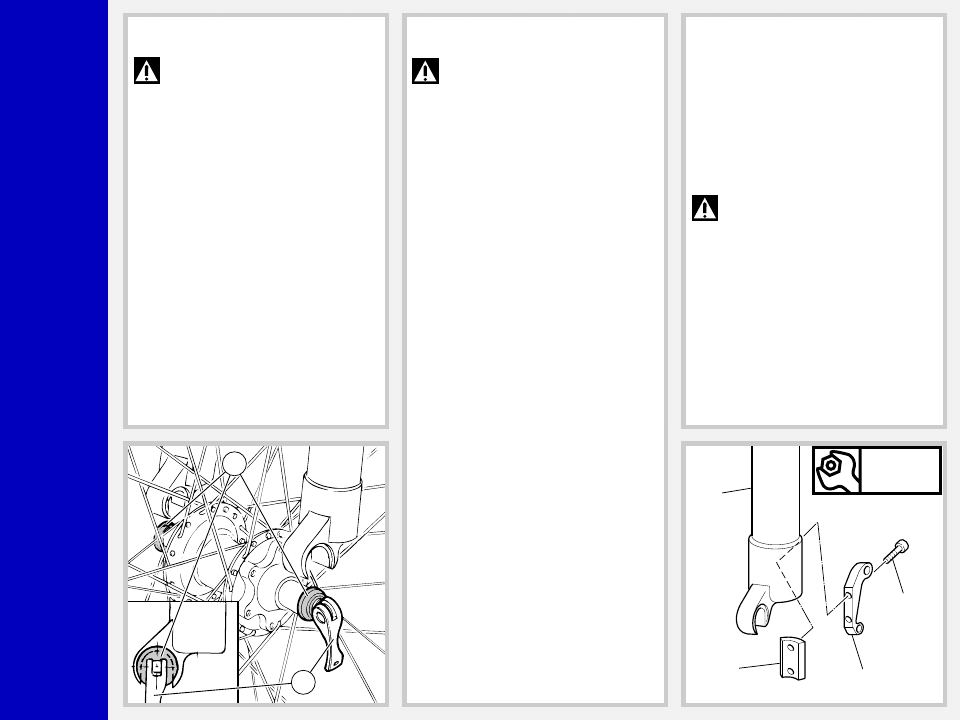
FRONT WHEEL ASSEMBLY (Fig. A)
IMPORTANT: fixing the front
wheel properly as specified in the
instructions given below is essential for the
proper operation of this fork and all re-
lated devices, and therefore for safe rid-
ing. You are advised to follow these
instructions closely.
Slacken the lock nut of the quick release
lever so the hub will fit between the fork
sliders.
Make sure the quick release bushings (C)
are centered to the recesses in the sliders.
Lock the quick release lever (D) and make
sure the bushings (C) are properly seated
in the sliders.
C
D
WARNING: These sliders are spe-
cifically designed to fit this type of
hub. Do not use any hub design other than
that specified here, as this would not
ensure proper fastening of the wheel and
may lead to breakdown of the assembly
components.
DISC BRAKE SYSTEM ASSEMBLY
(Fig. B)
Assembling the brake caliper onto the
slider is a very delicate operation that
should be carried out with extreme care.
Improper assembly might overstress the
caliper supports, which might break.
Screw the caliper support (31) to the slider
(16) using the screws (32) and plate (30).
IMPORTANT: Clean the mating
surfaces inside and outside slider,
otherwise dirt may affect caliper position
or cause the screws (32) to become loose.
Tighten the screws (32) to 9 Nm.
When installing the disc brake system, be
sure to properly follow the instructions
given by the manufacturer.
Nm
9
16
30
32
31
Z5
S
P
R
I
N
G
Q
R
2
0
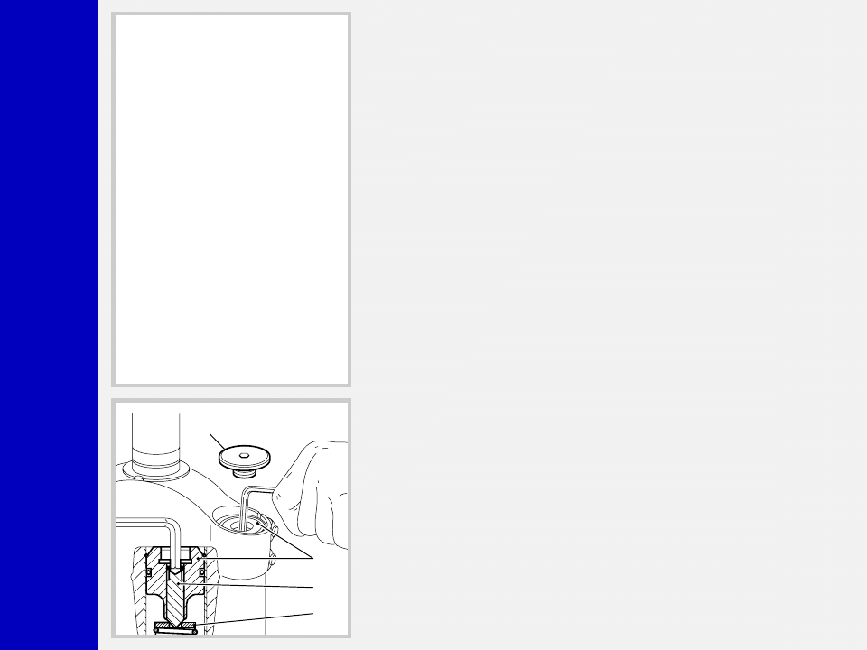
SPRING PRELOAD ADJUSTMENT
(Fig. C)
Take off the protection (2) using a 4mm
Allen wrench.
To change preload, turn the screw (35)
inside cap (4) with the same Allen wrench.
Turn out the screw (35) completely, then
tighten it until it touches the upper washer
(36). From this starting position, which
corresponds to “0” preload, turn in as
many turns as the preload you want. Each
turn corresponds to 1.25 mm (0.05 in.).
When supplied, Z5 is set with the mini-
mum preload. However, spring is slightly
preloaded to counteract static loads. By
turning the adjustment screw clockwise,
the preload is increased up to the maxi-
mum value equal to 15 mm’s/0.59 in. of
spring preload. This adjustment is essen-
tial in order to have the right Z5 response
for the rider’s weight and riding style.
2
4
35
36

Z5
S
P
R
I
N
G
Q
R
2
0
▲
▲
▲
▲
▲
▲
▲
▲
▲
▲
▲
▲
▲
▲
PUMPING ROD CHANGE
PILOT BUSHING AND SEAL
ASSEMBLY CHANGE
FORK OIL CHANGE
DUST SEAL FIG. 5
STOP RING FIG. 6
OIL SEAL FIG. 7
PUMPING ROD FIG. 10
REBOUND SPRING FIG. 10
STANCHION TUBE CAP FIG. 2
FOOT BUFFER FIG. 10
STANCHION TUBE FIG. 4
CAP / STOP RING FIG. 1
UPPER WASHER FIG. 8
PILOT BUSHING FIG. 9
FOOT NUT FIG. 3
DISASSEMBLY DIAGRAM
DISASSEMBLY
GENERAL
– The reference numbers given in this section relate to the components shown in the fork exploded view.
– Operations refer to the fork legs already removed from the crown and disassembled from the brake arch.
– Before starting any operation, please read the diagram below. It shows the quickest procedure and the exact disassembling
sequence. Locate the part you need to remove in the diagram, then look at the arrows to determine which other parts you will need
to remove first.

Z5
S
P
R
I
N
G
Q
R
2
0
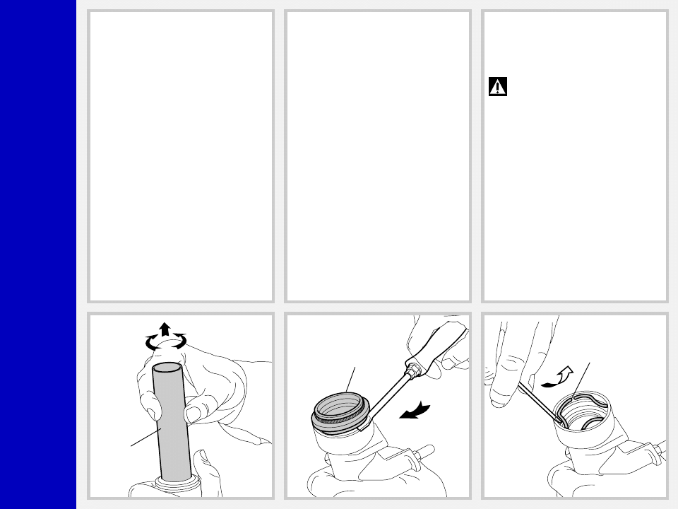
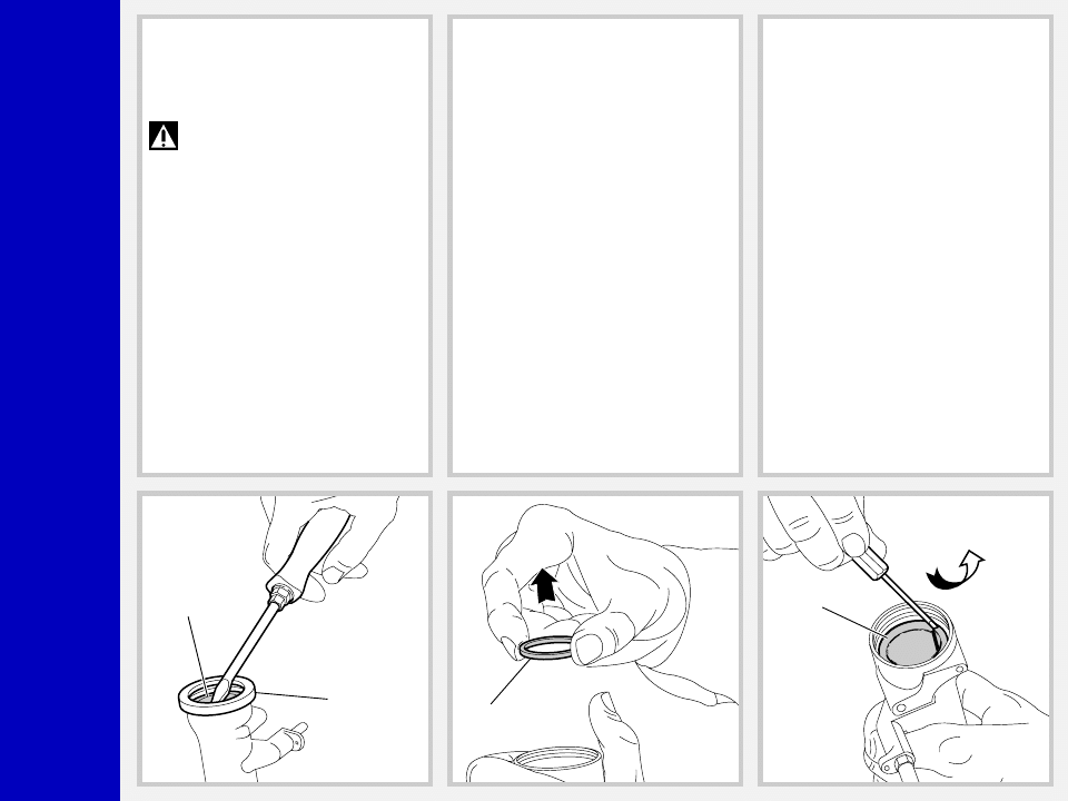
FIG. 1
WARNING: Any maintenance or
repair work may only be carried
out by reducing the preload of the springs
inside both fork legs by turning the screws
(35), as shown in Fig. A.
With a suitable rod, push the cap (4) into
the stanchion tube (9) just enough to
expose the stop ring. Remove upper stop
ring (3) using a screwdriver and keep
pushing the cap (4).
WARNING: once stop ring (3) is
removed, the thrust of the inner
spring (37) could make the cap (4) abruptly
come out of the stanchion tube.
Take all the measures necessary to pre-
vent this danger.
FIG. 2
Push the stanchion tube into the slider and
remove the washer (36) and the spring
(37).
Drain all oil from the fork leg.
WARNING: Remember to always
recycle any used oil.
To change the fork leg oil follow the
procedure as described in section
“REASSEMBLY” from Fig. 20 to Fig. 22.
FIG. 3
Turn the fork leg upside-down and un-
screw the foot nut (13) complete with O-
ring (12) by the use of a 15 mm socket
wrench.
9
3
2
37
13
12
Z5
S
P
R
I
N
G
Q
R
2
0
FIG. 4
Withdraw the stanchion tube (9) from the
slider.
9
22
21
PILOT BUSHING AND SEAL
ASSEMBLY CHANGE
FIG. 5
Remove the dust seal (22) from the top of
the slider using a small screwdriver.
FIG. 6
Remove the stop ring (21) from the slider
by placing the screwdriver bit in one of the
three openings on the stop ring.
IMPORTANT: when removing the
stop ring, make sure not to damage
its seat.
Z5
S
P
R
I
N
G
Q
R
2
0
FIG. 7
Fit the slider protector (A) onto the slider
and remove the oil seal (20) with the help
of a large screwdriver.
IMPORTANT: when removing the
oil seal, make sure not to damage
its seat. Once removed the oil seals should
not be used again.
20
A
19
18
FIG. 8
Remove the upper washer (19) from the
slider.
FIG. 9
Fit the bit of a small screwdriver into the
upper edge slot of the pilot bushing (18)
and lift gently. Pull the bushing out of the
slider and make all necessary changes.

Z5
S
P
R
I
N
G
Q
R
2
0
PUMPING ROD CHANGE
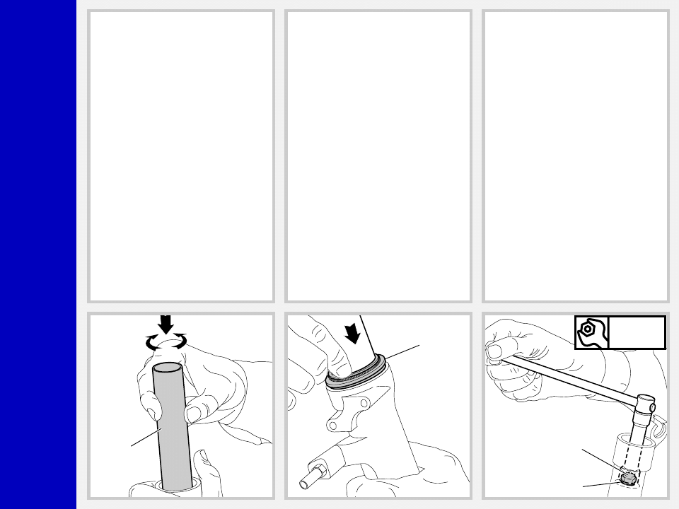
FIG. 10
Remove the foot buffer (10) from the
pumping rod (7) end.
Withdraw the pumping rod (7) and the
rebound spring (8) from the stanchion
tube opposite side. Replace the seal ring
(6) if damaged or worn out.
6
8
10
7

Z5
S
P
R
I
N
G
Q
R
2
0
REASSEMBLY
CAUTION: before reassembling,
all metal parts should be washed
carefully with inflammable, preferably bio-
degradable, solvent and dried with com-
pressed air.
PILOT BUSHING AND SEAL
ASSEMBLY
FIG. 11
Check that no dirt or debris is between
slider and bushing. Insert the pilot bushing
(18) into place so that it adheres to the
slider.
18
19
20
B
FIG. 12
Fit the upper washer (19) into the slider so
that it touches the pilot bushing.
FIG. 13
Lubricate the oil seal (20) and fit it onto the
seal press (B) with the hollow side toward
the slider.
Press the oil seal until it touches the upper
washer by using the above seal press.

Z5
S
P
R
I
N
G
Q
R
2
0
FIG. 14
Insert the stop ring (21) into the slider
making sure it is properly seated into
place.
21
7
9
8
6
10
7
PUMPING ROD ASSEMBLY
FIG. 15
After having overhauled or replaced the
pumping rod (7) and after having cleaned
the inside of the stanchion tube, reassem-
ble.
Fit pumping rod (7), seal ring (6) and
rebound spring (8) into the stanchion tube
(9) and push the rod until it comes out from
the other end.
FIG. 16
Reassemble the foot buffer (10) onto the
pumping rod (7) end.
Z5
S
P
R
I
N
G
Q
R
2
0
STANCHION TUBE ASSEMBLY
FIG. 17
Fit the stanchion tube (9) gently into the oil
seal (20).
Rotate the stanchion tube while inserting it
into the seal to facilitate installation and
reduce the chance of damaging the seals.
Turn the slider over and check that the
pumping rod thread is coming out from
slider bottom.
9
22
13
12
Nm
12
FIG. 18
Lubricate the dust seal (22) and fit it into
the stanchion.
Properly place the dust seal into its seat in
the slider.
FIG. 19
Grease the O-ring (12) on the foot nut (13)
and screw the nut onto the pumping rod
thread.
Tighten to 12 Nm.
Check to see that the stanchion tube slides
unrestricted by cycling the fork up and
down several times.
The tube should slide freely inside the seal
assembly without any side play.
In the event it is too hard or too soft, repeat
the previous steps described above check-
ing to ensure that components are not
damaged.

Z5
S
P
R
I
N
G
Q
R
2
0
HOW TO FILL WITH OIL
FIG. 20
Pour the oil little by little when the stan-
chion tube is fully down and then pump
the stanchion tube so as to have a better
filling. Check that the oil level is 48 mm/
1.89 inches from the top of the stanchion
tube, in both legs.
48
37
5
4
9
3
2
CAP ASSEMBLY
FIG. 21
Insert spring (37) inside stanchion tube.
Smear some grease on the O-ring (5) and
refit the cap (4) into the stanchion (9). Push
the cap down below the stop ring (3) seat.
FIG. 22
Refit the upper stop ring (3).
WARNING: while inserting the
stop ring (3), keep the cap (4)
pressed inside the stanchion tube using a
suitable rod, if necessary.
Refit the protection cap (2).
The brake arch can now be installed on
the fork leg, which should then be in-
stalled into the crown as specified in
section “INSTALLATION”.
Z5
S
P
R
I
N
G
Q
R
2
0
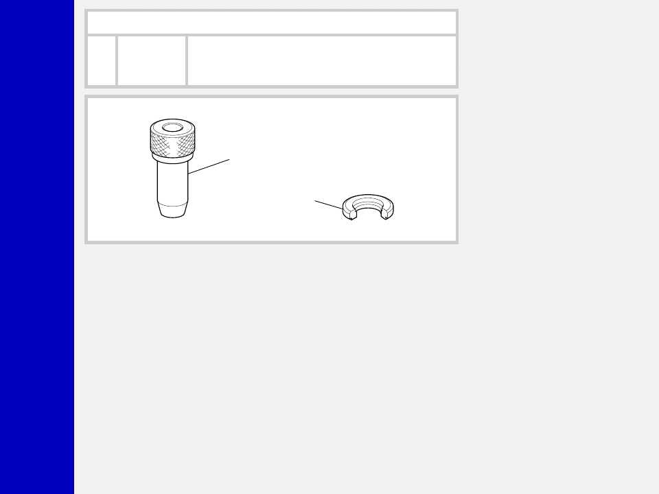
SPECIFIC TOOLS
Ref.
Item.
Description and use
A
536003 AB
Slider protector: to remove the oil seal from the slider
B
R 5068
Oil seal press: to press oil seal into the slider
A
B
Wyszukiwarka
Podobne podstrony:
2000 z5 qr20
2000 mr t qr20 service manual
2000 junior t qr20
2000 z1 qr20
2000 z5 flylight air
2000 z3 qr20
Breuer H P , Petruccione F (eds ) Relativistic quantum measurement and decoherence (LNP559, Springer
2000 z2 x fly qr20 service manual
03 2000 Revisions Overview Rev 3 1 03
Natura 2000
brzuch 1999 2000
MAZDA B3000 2000
krawiec 743[01] z5 03 u
2000
100618 podstawy ksztalcenia w zawodach z5
2000 12 03 wycena akcji, FCFF, FCFF, dźwignie finansowe, progi rentowności
więcej podobnych podstron