file:///H|/Modellismo/AFV%20Interiors/[armor]%20-%20AFV%20Interiors/afvinteriors.hobbyvista.com/vicmed/vicmed.html
British Medium Tank, Mk.I & II
The Vickers Medium Tank of the early 1920s probably best illustrates the renaissance of tank design
evolution in the British military establishment post World War I. Not only was this their first production tank
with a rotating turret, but the AFV could attain the unheard of speed of over 20mph, due to its sprung
suspension and air cooled engine. The vehicles also included a much improved internal ventilating system to
eliminate forever the high working temperatures of previous British designs. In some design aspects, the
tank's WWI ancestry still shows through, as with the hull side machine guns. Although there is little in the
general military print literature about the interior of these inter-war vehicles, we have gathered enough
information together to provide a general feel for what it was like to man one of these 15 ton AFVs. My
thanks go to Graham Matthews for helping to locate many of the illustrations for this page.
Picture 1:
The Vickers Medium Tank was simply a large armored box on tracks with a turret placed on top. Vickers-
Armstrong sent the first vehicles to the Central Tank School at Bovington for trials in early 1923. After a
brief improvement period, the first production vehicles (the Mk.I, known at that time as the Vickers Light
Tank Mark I) were provided directly to the Royal Tank Corps. They were quickly followed by improved
models Mk.IA, Mk.I*, Mk.II, Mk.II*, Mk.IIA and Mk.II**, each with slightly different armament and turret
detail changes. The production runs were made at both Vickers and the Royal Ordnance Factories.
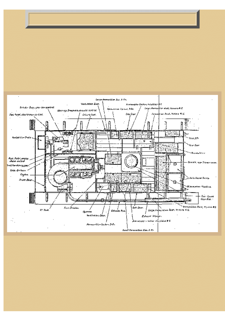
Here we see a layout drawing from the operator's manual of the Mk.I, which was the basic interior design for
all the Mediums. The bow of the vehicle is to the left, and includes the engine on the left side and driver's
position to the right, separated by a steel and asbestos wall. The engine in all the tanks is an Armstrong
file:///H|/Modellismo/AFV%20Interiors/[armor]%20-%20AF...teriors/afvinteriors.hobbyvista.com/vicmed/vicmed.html (1 di 6)07/02/2007 23.36.56
file:///H|/Modellismo/AFV%20Interiors/[armor]%20-%20AFV%20Interiors/afvinteriors.hobbyvista.com/vicmed/vicmed.html
Siddeley of 90hp, which is air cooled and developed from an aircraft engine. Drive from the engine was to a
multiple dry plate clutch and then to a 4-speed gearbox without syncromesh, proving that driving effort was
not considered in these early machines as very important design considerations. The gearbox was under the
commander's feet and the epicyclic steering mechanism, operated by levers on either side of the driver, was
mounted underneath the two fuel tanks attached to the interior rear wall (far right of the drawing). The
circular shape in the middle of the fighting compartment is a pedestal/platform for the gunner to stand on
while he attempted to aim and fire the 3pdr main weapon in the turret (there was no seat).
The other three men of the 5-man crew included the loader to the right of the gun, the radio operator/machine
gunner (when a radio was fitted) and commander/machine gunner, who viewed the world through simple
turret view slits as there was no cupola in these early machines. The three dark bins on each side of the hull
are for 3pdr and MG ammo storage, as are the three floor bins near the round pedestal.
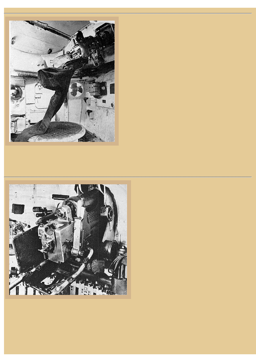
Picture 2:
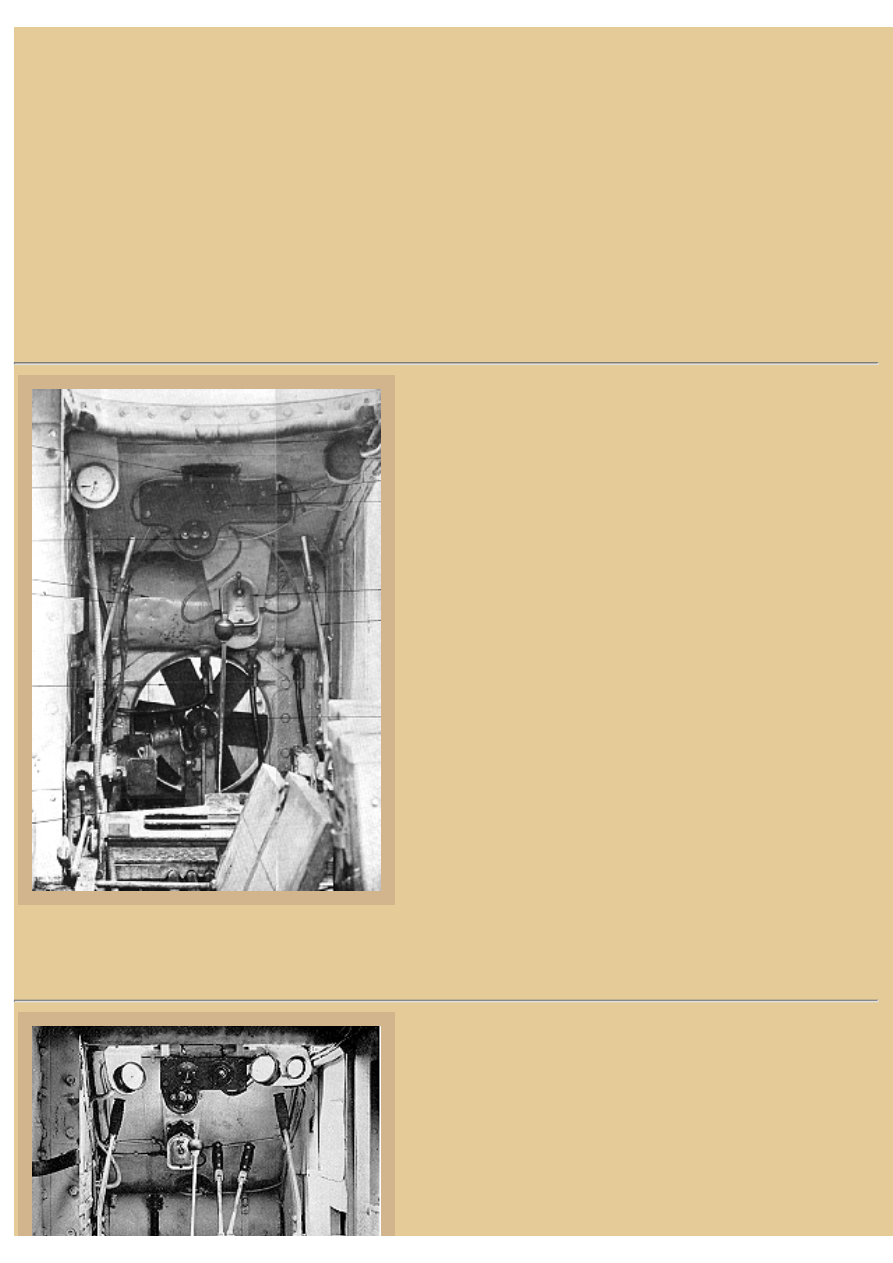
This is the driver's position in the early Mk.I, and I* series
vehicle. The driver had an excellent view through his
forward visor and overhead hatch when opened up, and a
padded bumper strip is seen at the lower edge of this
opening, at the top of the photo. To the left is a tachometer
("revolution counter") and the speedometer is off to the
right. On the small dark panel forward of us is the starter
switch, magneto switch and dimmer knob. Down below the
panel is a hand starting magneto switch while both steering
levers are seen to the right and left. The long rod with round
knob on top at the center is the gear shift lever ("change
speed lever") and the second set of dark levers well forward
and to the right are brake levers.
The large fan is part of the ventilating system that helped
make the interior of this vehicle far more pleasant for the
crew than the earlier rhomboid tanks, bringing in fresh air
from a vent in the hull above and blowing it past the driver
and into the crew compartment. To the bottom left of the fan
is a large square clutch pedal and to its right, and under the
center of the fan, is a narrow accelerator pedal. The seat
cushions have been removed for this operator's manual illustration and are seen leaning against the hull wall
to the right.
Picture 3:
This is a similar view, but of a Mk.II, IIA and II* vehicle
manual from the Imperial War Museum. The Mk.II was
very similar to the Mk.I vehicles but with a slightly
redesigned higher hull shape and thicker armor. The driver's
hood was also slightly changed, now standing proud of the
top of the hull as a separate hood with clamshell doors. The
file:///H|/Modellismo/AFV%20Interiors/[armor]%20-%20AF...teriors/afvinteriors.hobbyvista.com/vicmed/vicmed.html (2 di 6)07/02/2007 23.36.56
file:///H|/Modellismo/AFV%20Interiors/[armor]%20-%20AFV%20Interiors/afvinteriors.hobbyvista.com/vicmed/vicmed.html
other Mk.II types differed by the number and types of
machine guns in the turret and the general turret design. In
this photo the platform for the driver's seat is seen above the
connecting rods for the steering levers, which are to either
side of the compartment again. The parking brakes are now
rising from a common bracket on the floor and parting at
knee height to two black rubber grips. The tachometer is
still at the left and speedometer at the right, but an
additional gage next to the speedometer measures oil
temperature of the air cooled engine. Notice the diamond
pattern non-skid plating on the floor deck at the bottom of
the photo and the fan, barely visible behind the large clutch
pedal seems lower in the tank due to the increased height of the drivers seat. The interior of most interwar
British vehicles was painted white as WWI vehicles were. The later aluminum (silver) interior paint was not
applied until the late 1930s.
Picture 4:
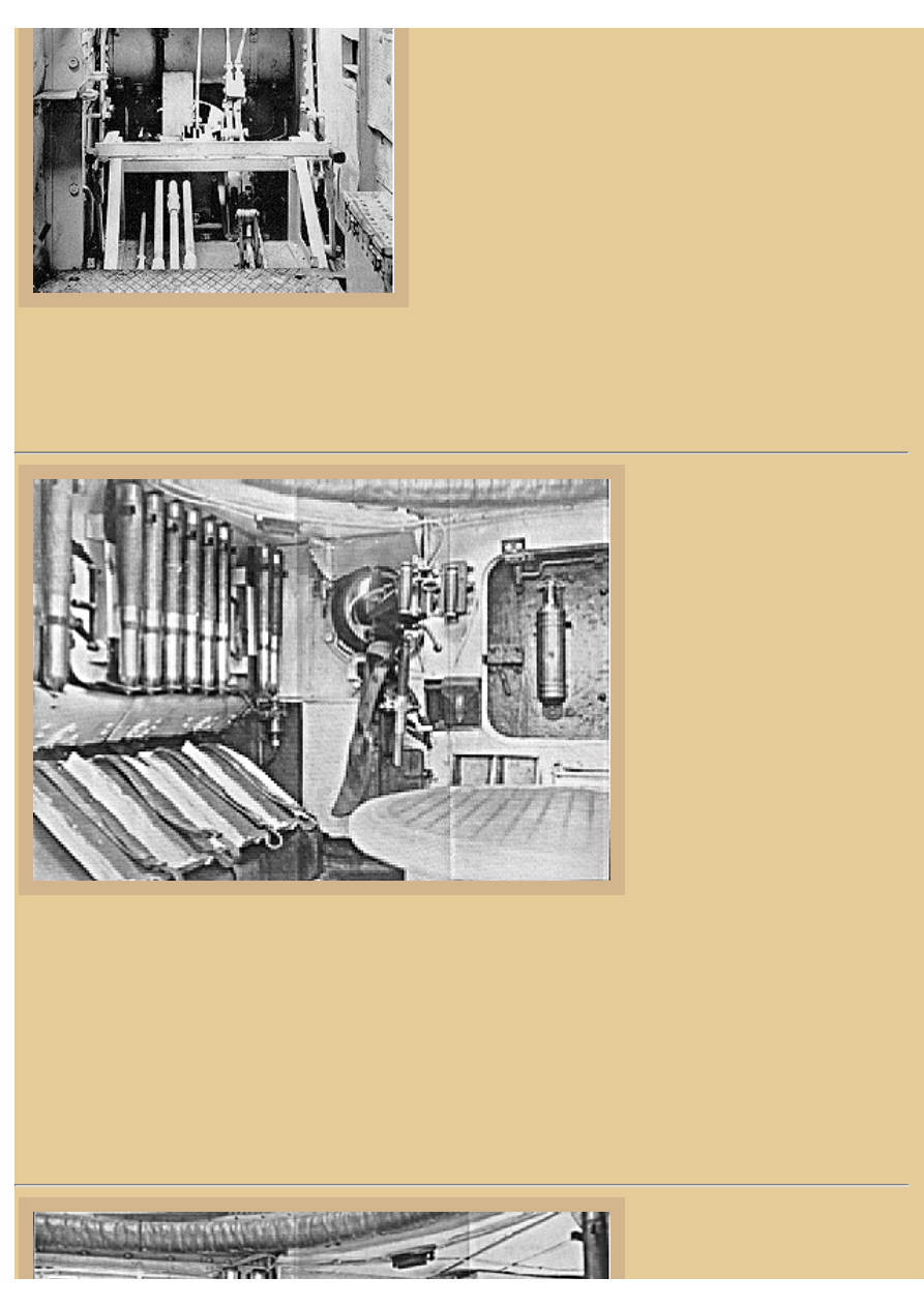
This is a photo from the
operator's manual again of the
Mk.I series, showing the left side
of the vehicle and rear wall with
3pdr shells in clips. The Mk.IA
was an improvement over the Mk.
I with a bevel at the rear of the
turret to improve fire from the
rear mounted Hotchkiss MG.
These vehicles had 4 Hotchkiss
MGs mounted in the turret, one
coaxial with the 3pdr, two at each
side of the turret, and one at the
rear. A fire extinguisher is
mounted to the left hull side door,
and one of the two hull mounted
Vickers MGs is seen behind the door in a ball mount. The Vickers .303in MGs fired around 500rpm and were
belt fed with spent shell casings falling into a long canvas bag below the gun (seen here). The twin handles of
the MG allowed a secure grip, but the weight of the gun required a screw elevation support under the
receiver, again seen here.
One of the more serious of the design flaws in this tank is the inclusion of the two fuel cells inside the
fighting compartment. They are seen here to the left of the photo, acting as the backing board for 3pdr. ammo
clips and storage. Even WWI rhomboid tanks mounted the fuel cells outside the vehicle in armored boxes at
the rear of the hull. The rear mounted transmission box access doors are seen under the fuel tanks and two
racks for Vickers MG ammo storage are seen partially hidden by the turret pedestal.
Picture 5:
file:///H|/Modellismo/AFV%20Interiors/[armor]%20-%20AF...teriors/afvinteriors.hobbyvista.com/vicmed/vicmed.html (3 di 6)07/02/2007 23.36.56
file:///H|/Modellismo/AFV%20Interiors/[armor]%20-%20AFV%20Interiors/afvinteriors.hobbyvista.com/vicmed/vicmed.html
The right side of the hull is
similar to the left seen above,
with the second Vickers MG with
armored jacket and ball mounted
is behind this side escape door
also. Again, a fire extinguisher is
mounted on the door, and the
hold open bar mechanism for the
door is seen mounted to the top.
Two 3pdr shells are clipped
between the door and Vickers
MG, and a 3-part bin for
additional ammo storage is off to
the right. At the right rear of the
hull was a full height door, just
out of view around the corner (to the right) in this photo. Notice the leather padding surround the turret ring
above. Total 3pdr storage was around 50 shells, and 6,000 rounds of MG ammo was typical. The Mk.IA*
differed from the previous models by the use of a an armored Vickers MG in the coaxial mount and the
addition of a small command post added to the top of the turret for the commander for better view. The
"Bishop's Mitre" could be rotated independently from the turret but had no glass blocks for its vision slits
located on both sides.
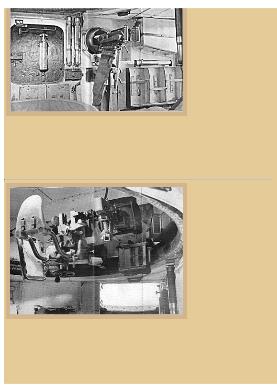
Picture 6:
This is another of the operator's
manual photos of the Mk.I series
vehicle, this time showing the
general layout of the front of the
turret. The Quick Firing 3pdr is at
the left and a Hotchkiss MG is
coaxial mounted at the right. The
3pdr has a geared traverse and
elevation, the traverse hand
wheel seen to the lower left of the
gun, and the gun itself is very
similar in design and appearance
to the 2pdr and 6pdr of WWII
vintage. A recoil shield is
mounted to the left of the gun to
protect the gunner standing on
that side and a rear shield
deflected spent shells into a long catch bag in front of the commander (the bag not mounted here). The sight
for the gun was a simple 1/1 telescope mounted to the left in the gun mantlet, and the coax. MG was fed from
the ammo rack seen below the gun. The 3pdr was fired by pressing the elevating hand wheel. Below the turret
can be seen the open driver's hatch of the early vehicle (notice it is lower than the top of the hull) and a
couple of rounds of 3pdr ammo are mounted on the hull wall at right. The Hotchkiss MGs were belt fed in
this application, and when mounted in the other positions in the turret walls had a pistol type grip mounted.
file:///H|/Modellismo/AFV%20Interiors/[armor]%20-%20AF...teriors/afvinteriors.hobbyvista.com/vicmed/vicmed.html (4 di 6)07/02/2007 23.36.56
file:///H|/Modellismo/AFV%20Interiors/[armor]%20-%20AFV%20Interiors/afvinteriors.hobbyvista.com/vicmed/vicmed.html
Picture 7:
This is the similar setup found in the turret of a Mk.II
series vehicle, this time with the long spent shell bag
attached. The Mk.IIA used a Vickers MG for the coaxial
mount and there is also a command post cupola on top of
the turret, just out of view in this photograph. An second
electrically operated ventilating fan has been added to the
left side of the hull, seen at the back of the photo. Notice
the frame for the sloping turret roof sides at the top of the
picture, and the ball mount for the Vickers in the hull side
behind the left side hull door. The hull interior was
relatively roomy in these vehicles; the driver's position
would be off to the right in the picture. You can imagine
what it must have been like for the gunner to stand on the
raised platform, bent over his sight and traversing the
turret while the tank lurched over uneven ground. There
is rubber or metal anti-slip tread on the raised platform,
but nothing more than the gun to hang on to during cross
country wild rides. Of course, tanks of this era were
required to halt before firing, which was probably of some consolation to the poor gunner and loader
balancing on the platform.
Picture 8:
This is a slightly clearer photo of a 3pdr (47mm)
weapon, this one mounted in the rounded turret of
an Independent Tank. The 3pdr is a semi-automatic
weapon with a falling vertical breech block, seen
here in the closed position. The striker is seen to the
rear of the breech as a small box with screw at the
rear. The recuperator is mounted along the top of the
gun, as it is in the 2pdr and 6pdr, and the support for
the spent shell bag is seen below and behind the
breech (bag missing here). The loader stood to the
right of the gun and pulled the breech lever, seen in
the upright and closed position here, to open the
breech to load the first round. Once it was shoved
into the breech, the block would close and the safety
switched off for the gunner to fire. After firing, the
block would open during recoil, the spent shell was
ejected and the block remained open for the next round to be loaded. In theory, the 3pdr was to have both an
AP and HE round provided, but the HE was rarely available, and as with its smaller and larger brothers the
3pdr was relegated by poor military planing to fire only the AP ammo. At that time, the machine guns were
thought to be enough to deal with infantry and lightly armored targets and the 3pdr was supposed to dispatch
any other unfortunate armored vehicles that wandered by. Unfortunately, this lack of tank battlefield
experience and foresight would plague the British Tank Corps well into WWII, with disastrous results.
file:///H|/Modellismo/AFV%20Interiors/[armor]%20-%20AF...teriors/afvinteriors.hobbyvista.com/vicmed/vicmed.html (5 di 6)07/02/2007 23.36.56
file:///H|/Modellismo/AFV%20Interiors/[armor]%20-%20AFV%20Interiors/afvinteriors.hobbyvista.com/vicmed/vicmed.html
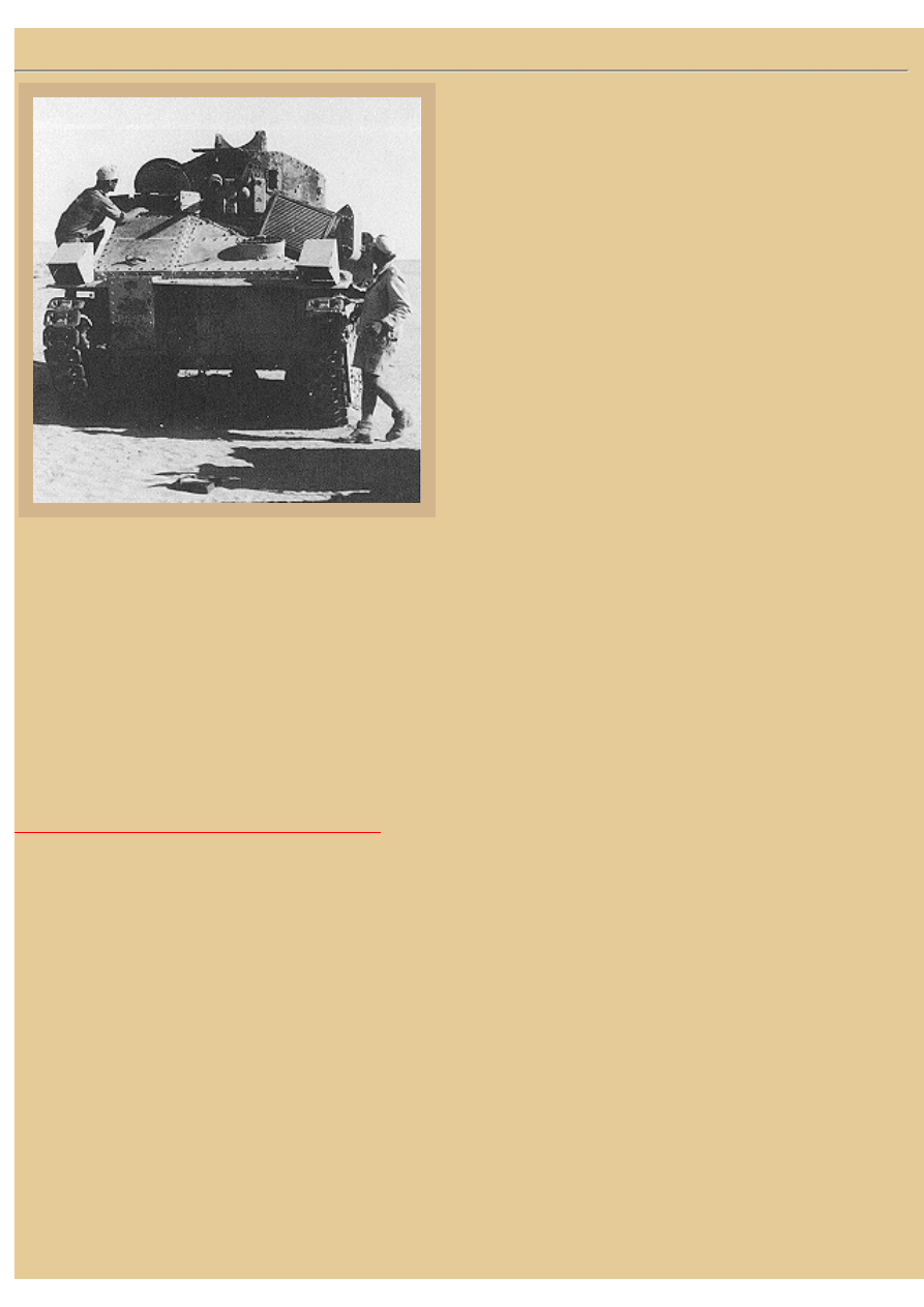
Picture 9:
Vickers Mediums were outdated and mostly used for
training by the beginning of WWII, but a few were
found in the North African desert by attacking German
troops in the early battles. I suspect that some were
attached to 6RTR early in 1939/40 while others are
known to have been used by the Australians in the
defensive battles around Mersah Matruh in '41. It is
unknown if these Mediums were actually used at that
time as maneuver tanks or were restrained to training
vehicles and static pill boxes. This photo from the
Bundesarchiv shows a Mk.II* with coaxial Vickers and
armored command post at the top of the turret (both top
hatches open), probably in the Mersah Matruh area.
Notice the driver's open 2-piece visor at the left as well
as one of the cooling grates over the engine compartment
that has been lifted at the right.
Overall, the Medium tanks built in the 1920s were experimental designs and most often used to train Royal
Tank crews battle and formation drill. Indeed, it was the speed of the vehicle that allowed field tacticians the
opportunity to practice "flying" formations. The Medium was further developed in a number of different
variations, including a close support version with a 3.7in howitzer. Of the 160 or so Vickers Mediums built,
most suffered through the financially difficult inter-war years with the Tank Corps. When finally mobilized
in 1939, the vehicle was quickly discovered to be too thinly armored to provide any real mobile armored
punch.
I am always on the lookout for further interior AFV information. If you would like to contribute any Vickers
Medium tank interior information please contact me at the e-mail address below and I will add it to the page.
BACK TO AFV INTERIORS HOME PAGE
(c) 2001, 2003 AFV INTERIORS Web Magazine
file:///H|/Modellismo/AFV%20Interiors/[armor]%20-%20AF...teriors/afvinteriors.hobbyvista.com/vicmed/vicmed.html (6 di 6)07/02/2007 23.36.56
Document Outline
Wyszukiwarka
Podobne podstrony:
AFV Interiors Czech Light Tank, LT vz 38, Pz Kpfw 38(t)
Afv Interiors Mk V
Afv Interiors Medium Tank Mark A whippet
Nissin Di866 mk II instrukcja
firearms ! Manual Sten MK II Submachine Gun
100W Guitar Amplifier Mk II
Lista V MK II
Programowanie pilota, AutoSerwis, Mondeo MK II
Lista III MK II
Montaż zimnej katody jako podświetlania zegarów w VW (na podstawie Golfa MK II), MOTORYZACJA, elektr
Lista IV MK II
Nissin Di866 mk II instrukcja
firearms ! Manual Sten MK II Submachine Gun
ebook Typy Broni i Uzbrojenia 132 Samolot mysliwski Hawker Hurricane Mk II IV
firearms ! Manual Sten MK II Submachine Gun
firearms ! Blueprint Sten Mk II Compact Submachine Gun Receiver Bond
74 ĽĘںʬ Mk IIÇ 228
akumulator do vauxhall vectra mk ii 18 16v 18 16v dualfuel 20
akumulator do vauxhall vectra mk ii 28 v6 turbo
więcej podobnych podstron