file:///H|/Modellismo/AFV%20Interiors/[armor]%20-%20AFV%20Interiors/afvinteriors.hobbyvista.com/whip/whip.html
WWI Medium Mark A Tank, "Whippet"
Picture 1:
The British Medium Mark A tank was a fast and lightly armed vehicle designed to exploit breakthroughs.
Manufactured by William Foster & Company Ltd., of Lincoln, the Mark A's crew of three included a driver,
commander, and one or two machine gunners who manned a total of four Hotchkiss MGs. It was in 1915 that the
engineering firm of William Foster & Co. Ltd. invented and produced the first tanks for Britain. Most of the
direction of that work was by the firm's General Manager, William Tritton, who was knighted in 1917 for this
work. Powered by two 45hp Tylor engines (each engine powered one track) the "Whippet", named after a popular
racing dog, could attain unheard of speeds of 9mph on roads, which was darn fast for tanks at that time. Armor
thickness ranged from 5-14mm, the armor bolted and riveted to a steel framework and purposely kept light to
allow for increased speed. The crews of the Medium Mark As saw their first combat during the battles around
Armiens in April of 1918.
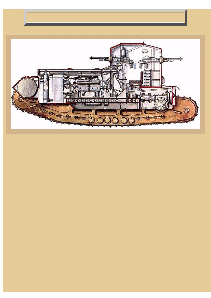
Our first illustration shows the left side view of the interior-- yes, the front of the tank is to the left. The driver's
seat is situated centrally in the taller portion of the vehicle which was called a turret (even though it did not rotate),
or cab, while the twin engines, fans, radiator, and fuel tank occupied most of the forward part of the hull. Notice
that the cylindrical fuel tank is mounted at the very front of the hull, perhaps not the best position in an otherwise
fairly well laid-out design. Directly behind the fuel tank is the radiator, and the large fan shroud lies directly
behind the radiator, the shroud housing two fans chain driven from the engines. The only other major problem
with Sir William Tritton's design, beside the forward mounted gas tank, was the use of two engines, each driving
only the track on that side of the vehicle. Internal combustion gasoline engines were not very reliable at that time,
even though these were two four-cylinder, in-line, commercial Tylor bus engines. Keep in mind that if an engine
were to stall or fail, the tank would only be able to circle, as only one track would then be powered, until the
stalled engine was restarted.
The only armament were Hotchkiss machine guns which could be mounted in the front, rear and sides of the
turret, the guns being supported in pivoting ball mounts. The sole crew access into the tank was via a door at the
back, next to the rear machine gun mount, although there was a small observation hatch on the roof that the
commander could use for observing the surroundings.
file:///H|/Modellismo/AFV%20Interiors/[armor]%20-%20AF...20Interiors/afvinteriors.hobbyvista.com/whip/whip.html (1 di 10)07/02/2007 23.31.52
file:///H|/Modellismo/AFV%20Interiors/[armor]%20-%20AFV%20Interiors/afvinteriors.hobbyvista.com/whip/whip.html
Picture 2:
We have just a few interior photographs of the Whippet, so I have reproduced them in large format so you can see
the most detail from each. This particular Whippet was photographed by Franck Soulier at the Royal Army and
Military History Museum, Brussels, Belgium. We are most fortunate that this tank has not been "reconditioned" so
it is in the same condition that it was when knocked out in 1918. As far as Franck can determine, the vehicle has
not been repaired nor repainted.
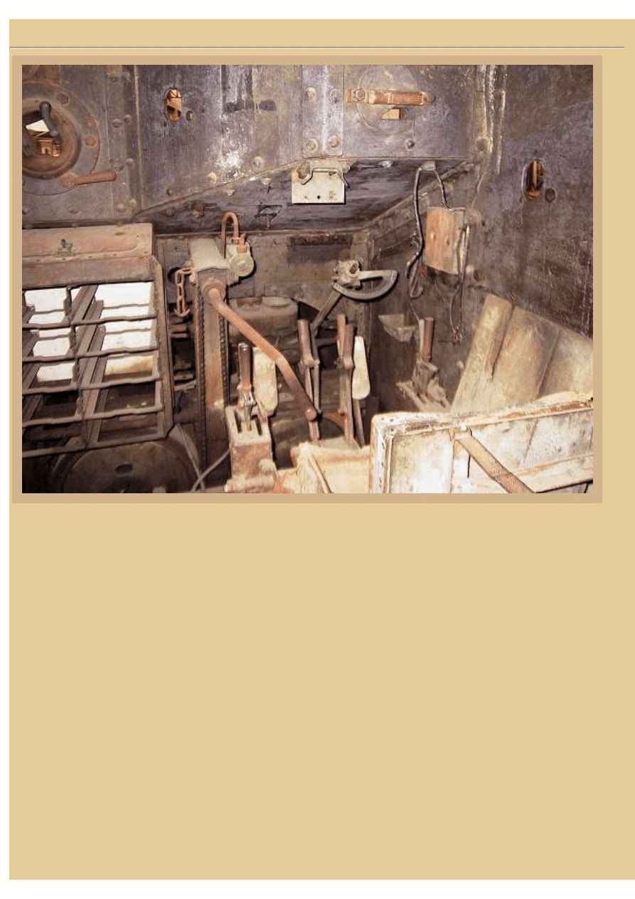
This first photo illustrates the driver's seat at the center right side of the fighting compartment as well as the
forward machine gun position to the left of the driver. The turret is not semetrical in shaped when viewed from
above. As you can see here, the left side of the front armor (where the MG is mounted) juts out forward, and the
right side of the front armor therefore is positioned further back near where the driver sits. There is a forward
vision slit for the driver with a rotating cover that is located directly in front of his face, and the cover can be
opened to any of a number of different positions depending on need and conditions. Note that the extended
forward-left side of the cab obscures the driver's view in that direction. In the photo you can see that his seat
appears to be covered in leather or a canvas fabric, and looking forward from the seat you can see the brake levers
for each sprocket as well as the handles of the gearshifts.
The driver normally steered the Whippet using a small steering wheel. Only the lower portion of the wheel is still
intact in this particular vehicle and you can see the wheel and its shaft angling up towards us, located between the
steering brake handles. The steering wheel shaft attached, via control links, to throttles on the carburetors of each
engine. By turning the wheel in one direction, you increased the speed of the opposite engine. That increased the
speed of the tracks on that side, subsequently steering the tank into the direction you turned the wheel. This
file:///H|/Modellismo/AFV%20Interiors/[armor]%20-%20AF...20Interiors/afvinteriors.hobbyvista.com/whip/whip.html (2 di 10)07/02/2007 23.31.52
file:///H|/Modellismo/AFV%20Interiors/[armor]%20-%20AFV%20Interiors/afvinteriors.hobbyvista.com/whip/whip.html
steering design, developed by Sir Tritton, was designed to avoid the loss of power found in the British heavy tanks
that occurred when a track was hand braked during a normal skid turn. However, driving the Medium Mark A was
still no picnic, first because it was one of the first British tanks with only one driver, and second because the driver
had to control both engines, while steering the vehicle with the wheel or manual braking levers. Notice the small
peephole on the right side of the hull, placed so the driver had a view (although restricted) out that side of the tank.
The oblong, rotating peephole cover is on the outside of the armor, as it is for most of these small peepholes on the
Whippet. Looking down and forward from the driver's seat, you can see twin foot pedals as well as the opening
leading to the engine compartment forward of the turret/cab area.
The ball mount for the .303in Hotchkiss MG is clear at the upper left of the photo, and a large bin for MG ammo
boxes sits directly below. These boxes were generally made of wood with handles on the ends-- you may recall
that Hotchkiss MGs used strip ammo feed, and the boxes held strips side by side, two strips wide. I suspect the
large hand crank you see was a starter handle, probably used mainly for restarting the engines after one had
stalled. There was also access for hand starting the tank outside the vehicle, from the rear of the cab.
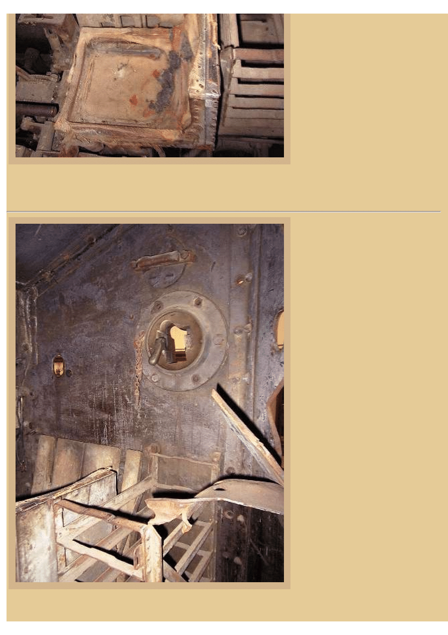
Picture 3:
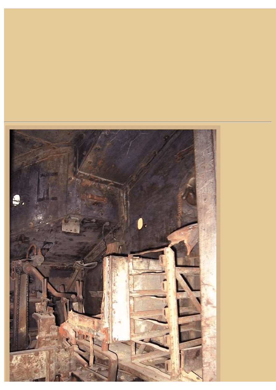
This view offers us
more detail below
the driver's seat
where the right
gearbox is located.
The gearbox for the
left engine is off to
our left, just out of
view. There was a
wood floor in the
fighting
compartment, which
is completely
missing here, and
normally the
commander stood at
this position, able to
look out of the
vehicle through a
roof hatch directly
above. Located on
the driveshaft
between each engine
and its gearbox is a
large flywheel,
located just on the
other side of the
forward partition
you see here. The
second driveshaft
that left the other
side of the four-
speed, constant
mesh gearbox then
proceeded on to a
file:///H|/Modellismo/AFV%20Interiors/[armor]%20-%20AF...20Interiors/afvinteriors.hobbyvista.com/whip/whip.html (3 di 10)07/02/2007 23.31.52
file:///H|/Modellismo/AFV%20Interiors/[armor]%20-%20AFV%20Interiors/afvinteriors.hobbyvista.com/whip/whip.html
final drive via a
worm gear. From
the final drive there
was a chain drive
that brought the
torque further to the rear of the hull to the rear drive sprockets. The chain drive is not drawn in the earlier diagram.
Again, remember that each engine is only connected to the drive sprocket on that side of the tank.
Major W. H. L. Watson was a tank commander in a Mark A Medium during WWI and following are some of his
recollections about a Whippet attack during the spring 1918 offensive. "All the tanks, except Morris's, had arrived
without incident at the railway embankment. Morris ditched on the bank and was a little late. Haigh and Jumbo
had gone on ahead of the tanks. They crawled out beyond the embankment into No Man's Land and marked out
the starting-line. It was not too pleasant a job. The enemy machine-guns were active right through the night, and
the neighbourhood of the embankment was shelled intermittently."
"Skinner's tank failed on the embankment. The remainder crossed it successfully and lined up for the attack just
before zero. By this time the shelling had become severe. The crews waited inside their tanks, wondering if they
would be hit before they started. Already they were dead-tired, for they had obtained little sleep since the long
painful trek of the night before. Suddenly our bombardment begun - it was more of a bombardment than a barrage
- and the tanks crawled away into the darkness. On the extreme right Morris and Puttock were met by tremendous
machine-gun fire at the wire of the Hindenburg Line. They swung to the right, as they had been ordered, and
glided along in front of the wire, sweeping the parapet with their fire. Serious clutch trouble developed in
Puttock's tank. It was impossible to stop since the German guns were following them."
"Money's tank reached the German wire. His men must have 'missed their gears'. For less than a minute the tank
was motionless, then she burst into flames. A shell had exploded the petrol tanks. A sergeant and two men
escaped. Money, best of good fellows, must have been killed instantaneously by the shell. Puttock's clutch was
slipping so badly that the tank would not move, and the shells were falling ominously near. He withdrew his crew
from the tank into a trench, and a moment later the tank was hit again." The quote is from Martin Gilbert's book,
"First World War" (May 1996, Henry Holt Publishers, ISBN: 0805047344).
Picture 4:
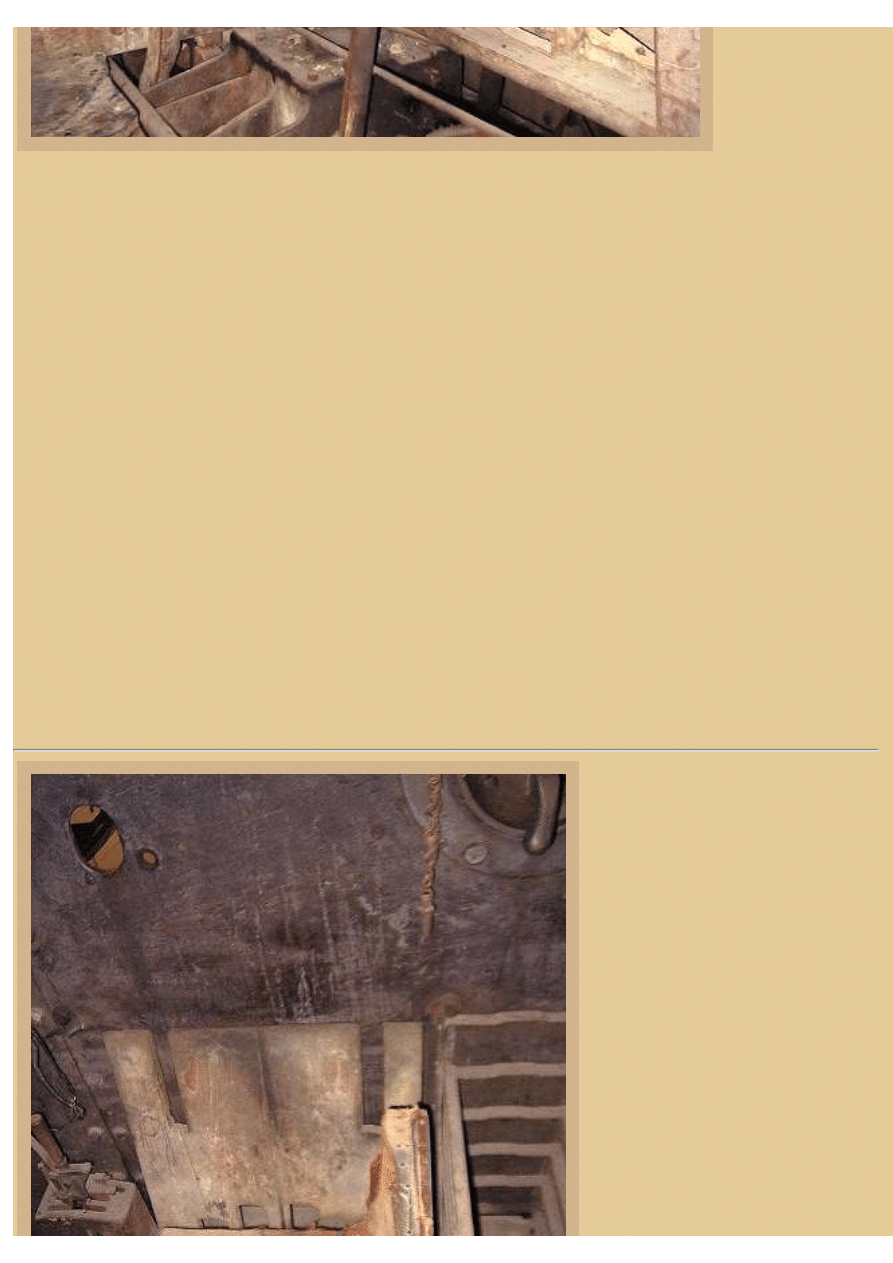
There isn't much remaining of the
driver's seat padding, but what little of
it that is left you can see in this photo.
Again, the brake levers are visible on
either side of the seat, and now the
ammo bin and MG ball mount on the
right side of the hull are also visible.
Once the Whippet saw its first action
in the spring of 1918 it was more or
less in continuous use until the end of
the war. Perhaps as many as 200
machines were constructed and those
that were not scrapped after the war
were sold to Japan and Russia.
Although turning the tank was
generally accomplished by turning the
steering wheel, straight driving was
normally accomplished by the driver
file:///H|/Modellismo/AFV%20Interiors/[armor]%20-%20AF...20Interiors/afvinteriors.hobbyvista.com/whip/whip.html (4 di 10)07/02/2007 23.31.52
file:///H|/Modellismo/AFV%20Interiors/[armor]%20-%20AFV%20Interiors/afvinteriors.hobbyvista.com/whip/whip.html
locking both output shafts by a splined
sleeve, therefore eliminating any
steering at all. All and all, the steering
system was very difficult to manage
for one man, and as I mentioned
earlier, stalled engines and constantly
circling Whippets were not rare
occurrences. On the other hand, the
Whippet was the first production
British tank with a turret (sometimes
also called a barbette), although non-
rotating. Range for the Whippet tank
that was intended as a breakthrough
exploitation machine was only 40miles (70 imperial gallons in the fuel tank). Crews liked more range, so you will
often see numerous gasoline tins strapped on the outside of the hull.
Picture 5:
Another picture of the right side of the
tank turret interior gives some
additional detail of the relatively
simple ball mount for the MG. The
pin hanging on the chain to the left of
the mount was inserted through the
mount and MG and held it in place.
Some sources record that there were
as many as 5,400 rounds of MG
ammo stored in the shelves. Viewing
of the fall of MG tracer rounds was
only possible by opening the peep you
see above the ball mount, the round
plate simply rotating out of the way.
Notice the bent armor plate visible to
our far right. The turret's right-rear
armor panel sustained a direct hit from
a large caliber artillery round that
splintered and penetrated the armor.
We will see a view of this damage
from outside the vehicle a bit later.
As I mentioned earlier, normal
steering was accomplished by using
the small steering wheel and varying
the speed of either engine/track. For
tight turns it was possible to place one
of the gearboxes in neutral and then
make a neutral turn. For an even
tighter turn, you could even apply the
hand brake to that same neutral track
if necessary. By the way, this is also
an excellent view of the angle iron
frame that supported the large armor plates, the plates either bolted or riveted in place.
file:///H|/Modellismo/AFV%20Interiors/[armor]%20-%20AF...20Interiors/afvinteriors.hobbyvista.com/whip/whip.html (5 di 10)07/02/2007 23.31.52
file:///H|/Modellismo/AFV%20Interiors/[armor]%20-%20AFV%20Interiors/afvinteriors.hobbyvista.com/whip/whip.html
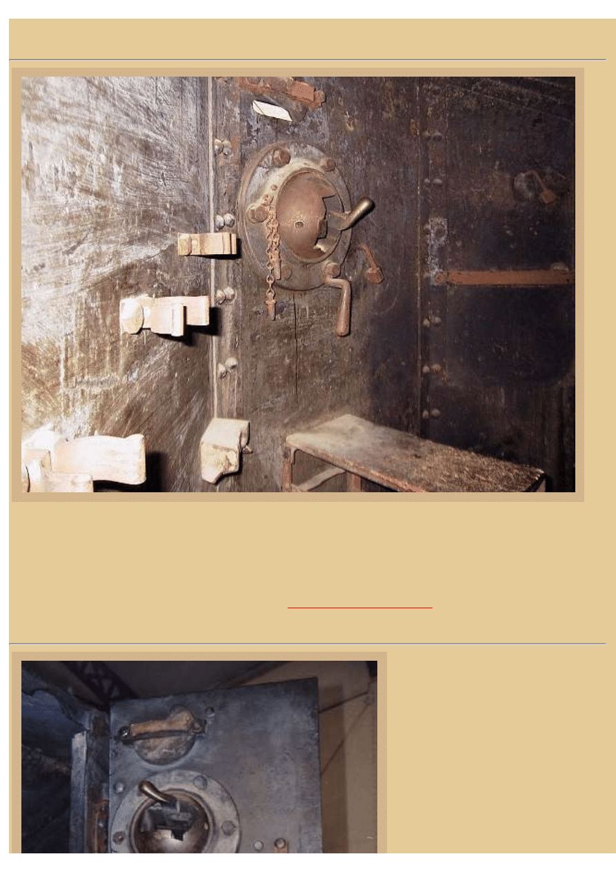
Picture 6:
The left side MG mount is identical to the others, and in this photograph is also another ammo bin as well as some
storage brackets on the angled left rear wall. In addition, the internal peep cover plate has been partially rotated
and you can see the vision slot now exposed in the armor plate. The clips you see on the wall may have been used
for storing the Hotchkiss MGs when they were not in use, but that's just speculation on my part. There is
additional information concerning the Hotchkiss MGs that were used in the Whippet in other pages of AFV
INTERIORS Web Magazine, such as the page on the
Picture 7:
The rear door is open on this museum-
preserved Whippet and this is the detail
of the inside surface. The ball mount is
missing its MG securing pin, but the
handle below the mount that helped
steady the gunner is clearly visible.
Again, there is a peep lookout above the
ball mount and it opens in the same
manner as the others we have seen.
Inside the vehicle is visible some of the
ammo bin that was bolted to the right
file:///H|/Modellismo/AFV%20Interiors/[armor]%20-%20AF...20Interiors/afvinteriors.hobbyvista.com/whip/whip.html (6 di 10)07/02/2007 23.31.52
file:///H|/Modellismo/AFV%20Interiors/[armor]%20-%20AFV%20Interiors/afvinteriors.hobbyvista.com/whip/whip.html
rear corner of the tank. Next to this bin is
a second bin used to store crew
equipment that has no shelves.
The British introduced tank warfare to
the world on the Somme battlefield,
using their Mark I tanks, on September
23, 1916. The following year the massed
tank attack at Cambrai failed partially
because the heavy tanks had been unable
to continue their breakthrough advance.
Eventually, most of the hard fought
ground was once again lost to the
Germans in counter attacks, and this was
very hard to accept by the officers that
had been involved. There was much
letter writing and finger pointing, and so
it was in December of 1917 that the
Ministry of Munitions authorized
production of the Medium Mark A
Whippet as a true exploitation tank.
Incidentally, one of the ways that you
can determine that the Whippet was
manufactured late in the war is the
presence of ball mounts for the machine
guns. MG mounts in earlier heavy tanks used a simple slit in the armor for firing access, and enemy return fire
often penetrated the openings and seriously injured the occupants.
Similar to earlier tank designs, there was no protective firewall between the engine and crew compartments in the
Medium Mark A. The cramped three or four-man crew was therefore exposed not only to the noxious gases
produced by the twin bus/truck engines and gearboxes, but also to the heat and tremendous noise, just a few feet
away. The follow-on design to the Medium Mark A "Whippet" was the Medium Mark B (also called Whippet on
occasion), and it did finally separate the engine and fighting compartment with a genuine firewall, much to the
relief of the crew.
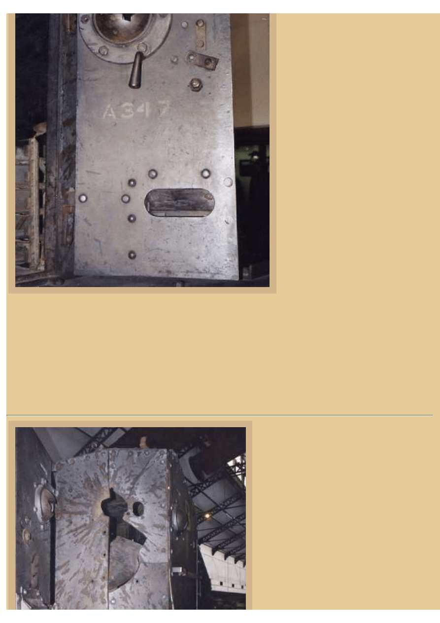
Picture 8:
This is the penetration damage I mentioned
earlier, the full impact of the piercing round
evident from the shattered plates and spalling
you see radiating out around it. This must have
been a catastrophic hit for the crew if they were
inside at the time, and the hit explains the
discoloring inside the tank. Interestingly, the
penetration does not seem to have resulted in
an internal fire. The open rear door is to our
left.
The Whippet suspension was unsprung, that is
the boogies were bolted directly to the hull and
carrier rail. The boogies consisted of twenty
rollers on the bottom run to carry the weight,
file:///H|/Modellismo/AFV%20Interiors/[armor]%20-%20AF...20Interiors/afvinteriors.hobbyvista.com/whip/whip.html (7 di 10)07/02/2007 23.31.52
file:///H|/Modellismo/AFV%20Interiors/[armor]%20-%20AFV%20Interiors/afvinteriors.hobbyvista.com/whip/whip.html
while other lighter rollers were provided on the
top run to carry the track back again. The use
of return rollers on the Whippet is in stark
contrast to the purely slide track return method
used on British heavy tanks at that time, which
was much nosier and harder on the material in
contact. The track shoes, or plates, on the
Medium Mark A were 20.5in wide and similar
in design to those of the British heavy tanks,
but they were also lighter in construction. The
tracks were designed for the addition of special
metal and wood spuds to deal with unusually
heavy going, and in some photos you will see
the wooden spuds hanging side by side on the
hull, appearing like so many wooden blocks
lined up along the hull.
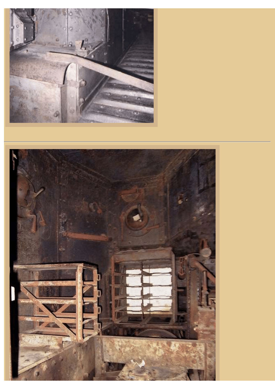
Picture 9:
Our final interior
photo of the vehicle
from the Danish
Military Museum
brings us back to the
front of the cab
again. Both forward
and left side MG
ammo bins are
visible here, as well
as the second
gearbox located
below us, visible
because the wooden
floor is missing.
From what I have
seen in period
photographs, British
tank crew uniforms
seem to have
changed a couple of
times during the
Great War. By the
time the Whippet
went into action in
1918 most crews are
seen to be wearing a
drab light brown or
perhaps tan overall,
typically with the
common steel
file:///H|/Modellismo/AFV%20Interiors/[armor]%20-%20AF...20Interiors/afvinteriors.hobbyvista.com/whip/whip.html (8 di 10)07/02/2007 23.31.52
file:///H|/Modellismo/AFV%20Interiors/[armor]%20-%20AFV%20Interiors/afvinteriors.hobbyvista.com/whip/whip.html
helmet, and
normally their dress
tunic worn over the
overall. Regulation
leather equipment
belts of the 1916
issue were also worn
throughout the war
over the tunic. In warm weather you will also see photos of tank crewmen wearing khaki shorts with puttees and
boots. Almost always present and part of the official uniform were the large gas mask satchels worn around
tankers necks, as the danger of gassing was an ever-present danger to tankers also.
Inside the satchel was a canister gas mask, which was originally developed in England to protect soldiers from
chlorine gas and other tearing agents such as xylyl bromide. These masks were not able to filter the more deadly
phosgene and diphosgene gases. And, there were no masks for any soldiers in the Great War that could protect
them from the feared mustard gas, which attacked all flesh that happened to be exposed at the time. It has been
written that in 1918 a German corporal, Adolf Hitler, was temporarily blinded by a British gas attack in Flanders.
Having suffered the agonies of being gassed himself, Hitler's fear of gas attacks may have deterred him from
deploying it as a tactical weapon on the battlefields of WWII.
Picture 10:
Although the Germans were the first to
introduce gas onto the battlefields of WWI in
1915, it didn't take long for the other
belligerents to follow suit. At that time there
were two ways to gas your enemies, either by
cylinders or by projectiles. The cylinder
attack required bringing a large number of gas
cylinders up to the line and then running pipes
from these as far forward into No-Man's Land
as possible. When the wind was just right, a
dense cloud of gas could be released that
would envelope a large section of the
defensive trenches. Of course, the wind was a
distinct disadvantage for the Germans, as
prevailing winds across France are typically
from the west to the east, against them. The
primary gasses used through the first half of
the war were phosgene and chlorine.
The second method of gas attack required
projectiles to be fired from guns or trench
mortars. This method did not require as much
reliance on the wind, and rear areas could also
be attacked, but heavy bombardments were
also generally required. By the time the Whippet came into the war, mustard gas had become the most prevalent
gas weapon. It has been estimated by British sources that as many as 160,000 of their soldiers were incapacitated
and as many as 4,000 killed by mustard gas attacks from the July 1917 to November 1918.
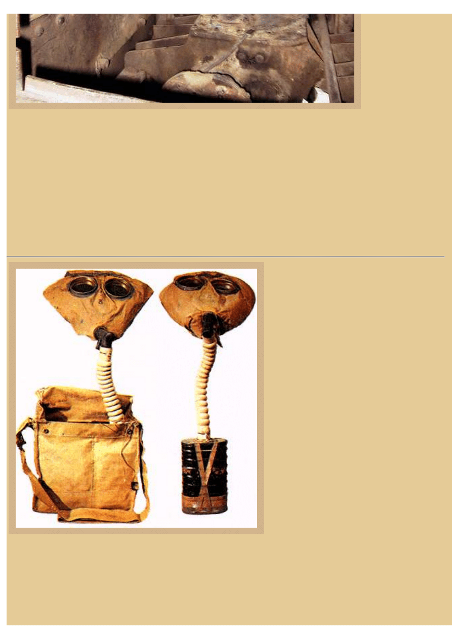
The typical British Model 1917 small box respirator and carrying satchel are on the left; it was the most common
gas mask in British use at the time, both for infantry and armor units. It had replaceable, non-splintering eyepieces
file:///H|/Modellismo/AFV%20Interiors/[armor]%20-%20AF...20Interiors/afvinteriors.hobbyvista.com/whip/whip.html (9 di 10)07/02/2007 23.31.52
file:///H|/Modellismo/AFV%20Interiors/[armor]%20-%20AFV%20Interiors/afvinteriors.hobbyvista.com/whip/whip.html
as well as a breathing outlet valve, and was therefore more comfortable to wear than its German counterpart. In
fact, the model 1917 was probably the best gas mask of the war, and it was generally proof against all gasses
except, of course, mustard. That is because mustard gas is a vesicant gas, causing blistering on skin contact, and it
does not have to be breathed into the lungs to be effective. The small box filtering unit is seen at the right, and in
this case there appears to have been a second filter added at the bottom. The design of this mask was for the user
to breath in and out normally, breathing in through the filter box and out via the valve mentioned earlier, located
where the hose attached to the mask.
Picture 11:
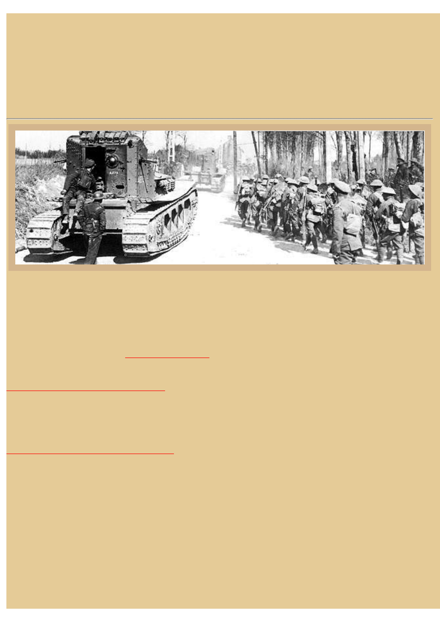
Although plagued with more than its fair share of mechanical problems due to the unique layout of the twin bus
engines and the driver's controls, the Whippet was an effective, if short-lived tank and played an important role
during the final years of WWI. Like most early tank designs, it provided a terribly uncomfortable ride for the crew
and its purposely-designed short hull (required to reduce weight) created a tendency for vertical oscillations that
was a bit like riding high waves at sea. The particular Whippets illustrated in this photograph are part of the 3rd
Battalion at Maillet Mailly, France, March 30, 1918. They are accompanying infantry of the New Zealand
Division. The photo is from the
My thanks again to Franck Soulier for loaning us his photos of the Whippet preserved in the collection of the
Royal Army and Military History Museum
in Brussels, Belgium. Should you have additional information about
the interior of the Medium Mark A, we would be interested in sharing it with out readers. There is currently not
much material available on the Whippet, and we all hope this page continues to grow over time as additional
information is added.
BACK TO AFV INTERIORS HOME PAGE
(c) 2002, 2003 AFV INTERIORS Web Magazine
file:///H|/Modellismo/AFV%20Interiors/[armor]%20-%20AF...20Interiors/afvinteriors.hobbyvista.com/whip/whip.html (10 di 10)07/02/2007 23.31.52
Document Outline
Wyszukiwarka
Podobne podstrony:
AFV Interiors British Medium Tank Mk I & Mk II
AFV Interiors Czech Light Tank, LT vz 38, Pz Kpfw 38(t)
T 64B medium tank
T 64A medium tank
T 64BV medium tank
T 64 medium tank
T 55 medium tank
T 54 medium tank
AFV Interiors Water Buffalo
Afv Interiors Isu 152
AFV Interiors CV 33 35
AFV Interiors German AFV Radio Equipment In WWII
AFV Interiors M1A2 Abrams
AFV Interiors Leopard 2
Afv Interiors Daimler Scout Car
AFV Interiors Otter
AFV Interiors B1 bis
Afv Interiors Mk V
AFV Interiors Marder III
więcej podobnych podstron