
file:///H|/Modellismo/AFV%20Interiors/[armor]%20-%20AFV%20Interiors/afvinteriors.hobbyvista.com/mkv/mkv1.html
British Mk.V* Tank
Picture 1:
The British
Mk. V* tank
was a
continuation
of British
WWI tank
development
that had begun
with the Mk.I
design of
1916. The Mk.
V* was a
lengthened
Mk.V, the
only
difference
between the
two being
additional plates that were added to the Mk.V behind the gun sponsons to lengthen the hull for improved trench crossing and
provide additional internal space for carrying troops or equipment. Except for the extra armor plates, the running gear and
other automotive components were almost identical in the Mk.V and Mk.V* tanks. This is a photo from the
the additional plates to make the lengthened chassis of the Mk.V*.
There were a number of improvements in the Mk.V and Mk.V* over their predecessors (like the famous Mk.IV) which
greatly changed the way the crew managed the tank. For instance, the Mk.V and Mk.V* tanks featured a new Wilson
epicyclic gearbox and brake that replaced the earlier change-speed gearing. The new steering system required only one
steering crewmember, rather than the two used previously, the new driver called the "operator". Another important change
was that both the Mk.V and Mk.V* were powered by the purpose-built Ricardo tank engine which required less service and
broke down less frequently than the previous engines. The Mk.V* went into production at Metropolitan Carriage and Wagon,
Birmingham, in December of 1917.
This is the first part of a two-part exploration of the interior of the Mk.V* WWI tank. This series is an improved and
expanded version of a web page first published in AFV INTERIORS in 1997.
file:///H|/Modellismo/AFV%20Interiors/[armor]%20-%20AFV%20Interiors/afvinteriors.hobbyvista.com/mkv/mkv1.html (1 di 7)25/05/2007 16.54.45
file:///H|/Modellismo/AFV%20Interiors/[armor]%20-%20AFV%20Interiors/afvinteriors.hobbyvista.com/mkv/mkv1.html
Picture 2:
As I mentioned, the Mk. V* was simply a Mk. V tank lengthened by six feet behind the side sponsons with the intention of
improving its trench crossing ability as well as providing transport space for troops or supplies. Initially, Mk. V* tanks
originated as Mk. Vs that were altered in workshops in France, lengthened by the addition of three 2ft wide plates. But later
production tanks were special made in England to this new length. Overall, roughly 580 Mk. V* tanks were produced and had
just come into service when the Armistice was signed to end WWI.
The Mk. V* proved to be a robust design and it was a very handy vehicle with its increased payload area. Some were used,
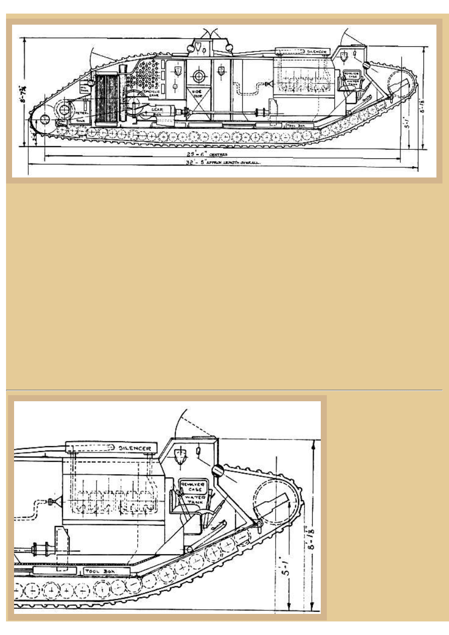
for instance, by the US 301st Tank Battalion which operated under British control at the end of the Great War. This diagram
from the Imperial War Museum shows the basic layout of the Mk. V* with driver sitting up front (our right). He is now the
sole controller of the tank, using a 4-speed gearshift lever and two steering levers to control the steering and brakes on the
epicyclic gearbox. Next to the driver (on his left) is a front hull machine gunner, and behind the driver is the new Ricardo
engine with exhaust pipes exiting the tank directly over the engine through a muffler system. Behind the engine is the
expanded cargo area, and after that is the gearbox, epicyclic gears, and the radiator and fan. In the very rear of the vehicle,
actually outside the rear plate, are the three gas tanks between the rear drive sprockets. There were gun sponsons located on
each side of the tank, and if it were mounted with 6pdr guns the vehicle was termed a male and if machine guns were the sole
armament the tank was called a female. Let's take a closer look now at this drawing and see what detail is hiding there for us
to discover.
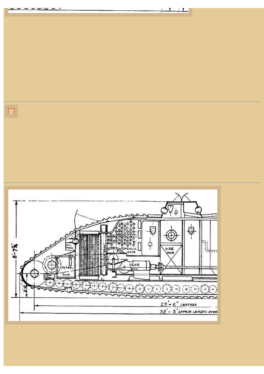
Picture 3:
This is a detail study of the front
of the tank, mainly showing the
operator's position. His seat is
just about directly in front of the
engine, and he is provided with
an opening visor flap for
forward viewing. There is also
an over-head hatch for entrance
and exit, should his way be
blocked back through the
vehicle on either side of the
engine. The engine behind his
seat is covered with a metal
shroud to protect the crew from
direct contact and a fan at the
rear of the shroud forces air
from around the engine through
a ventilation grating on the roof.
This helps to remove the heated
air around the engine that may
file:///H|/Modellismo/AFV%20Interiors/[armor]%20-%20AFV%20Interiors/afvinteriors.hobbyvista.com/mkv/mkv1.html (2 di 7)25/05/2007 16.54.45
file:///H|/Modellismo/AFV%20Interiors/[armor]%20-%20AFV%20Interiors/afvinteriors.hobbyvista.com/mkv/mkv1.html
also contain fumes. As far as I
can tell, this is the first time consideration of the crew from heat and fumes was shown by isolating the engine. There is a
water tank and revolver case for the front crewmen located in the left side wall, under the track run, to the left of the machine
gunner sitting to the left of the driver.
Some of the driver's controls are drawn here and they include his forward-reverse lever that you see rising and angling
slightly back, located on the right side of his seat. Three other levers rise on either side of his seat and here these levers are
seen angling forward. Two of them are his control levers, one at each side of the seat, and they steer the tank via the
epicyclics at the rear. The other control lever is also located to the right of his seat, but it is the "change gear" lever, the
gearshift. You can also see the location of the foot pedals mounted down on the floor; there is a clutch pedal to the left and a
brake to the right. These will be seen better in the next drawing. Notice that the engine is elevated on a shelf. Power is
transferred from the engine to the driveshaft down near the floor via gears around the flywheel and at this end of the
driveshaft.
Picture 4:
This is an overhead view of the driver's area of a Mk.V, more or less the same layout that existed in our Mk.V*. Now
the relative locations of the driver's and gunner's seats are shown in relation to the engine and its protective shroud.
Notice that the water tank and revolver case are in the sponson to the gunner's left, and the driver's seat is just about
surrounded by control levers of one type or another. The steering levers are drawn very close to his seat, while the change
speed and forward/reverse levers are a bit further away to his right. The brake and clutch pedals are also shown, as well as
something called an officer's locker in the sponson to the driver's right.
The inline design of the Ricardo engine is shown, with the carburetor on the left and the intakes curving around to the right.
Notice that a water hose is shown leaving the top of the case and turning to the rear where it travels along the ceiling back to
the radiator at the right-rear of the tank. We will see this hose later in a picture taken inside the vehicle.
Picture 5:
And this is an
enlargement of
the same sketch
showing the rear
half of the tank.
The driveshaft
arrives at the
Wilson gearbox
you see here from
the engine at the
front of the tank,
and from the
gearbox the drive
is directed
sideways to
epicyclic gears
mounted on both
sides of the hull.
These gears then
provide power
through chain
drives to
reduction gears that directly engage the drive sprockets, utilizing the same gear teeth that engage the track. The three armored
fuel tanks are shown attached to the rear of the hull, while the single oil tank is drawn above them. Also on this rear armor
wall is a ball mount for a machine gun, similar to the two others you see in the cupola, or turret, up on the roof. This cupola is
just an iron box and does not rotate, but it does provide improved vision around the tank and a good place to mount machine
guns fore and aft.
file:///H|/Modellismo/AFV%20Interiors/[armor]%20-%20AFV%20Interiors/afvinteriors.hobbyvista.com/mkv/mkv1.html (3 di 7)25/05/2007 16.54.45
file:///H|/Modellismo/AFV%20Interiors/[armor]%20-%20AFV%20Interiors/afvinteriors.hobbyvista.com/mkv/mkv1.html
The series of vertical parallel lines in front of the oil tank identifies the tall water radiator for cooling the engine. This was
composed of a number of vertical pipes with spaces between for air to flow through. Hot water from the engine was pumped
into the top of the radiator and then the radiator-cooled water was returned to the engine from the bottom. The water tank
(header) is is shown located directly in front of the radiator. On both walls, located both in and outside the sponsons, are racks
and storage tubes for many 6pdr. rounds (if the tank is a male), and the new side doors (in the lengthened section of tank) are
also identified in this sketch under ball mounts for two more machine guns.
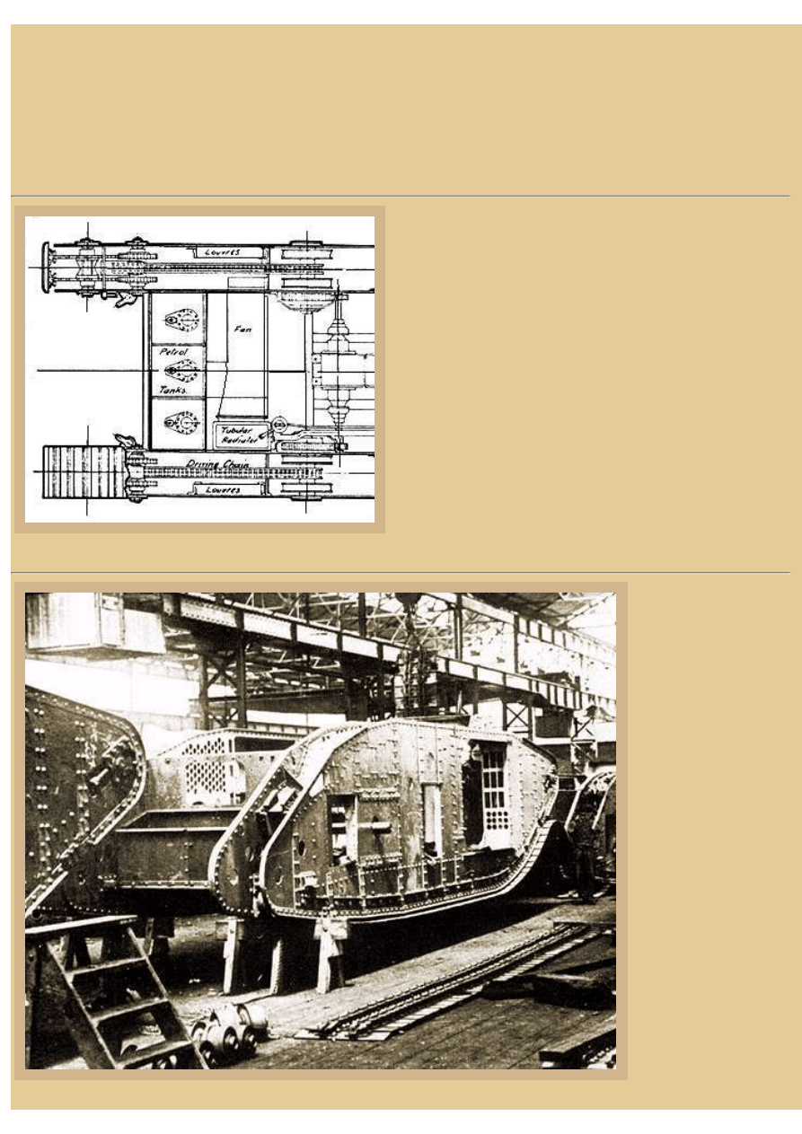
Picture 6:
The top view shows the location of the three fuel tanks at the
rear of the tank, separated from the hull interior by a steel
bulkhead. The location of the fan shroud on the left side of the
hull and the tubular radiator on the right is also clear. The
radiator is also shrouded so air drawn into the fan from the left
is blown across the radiator and exhausted through the louvers
on the right hull wall. Note that the water tank illustrated in the
last picture is a vertical tubular type that is located in front of the
radiator. The epicyclics are indicated by the metal covers that
look like bulges on the interior hull walls. The chain drive is
illustrated running from the epicyclic gears to smaller reduction
gears, which then directly engage the drive sprockets at the stern
sponsons.
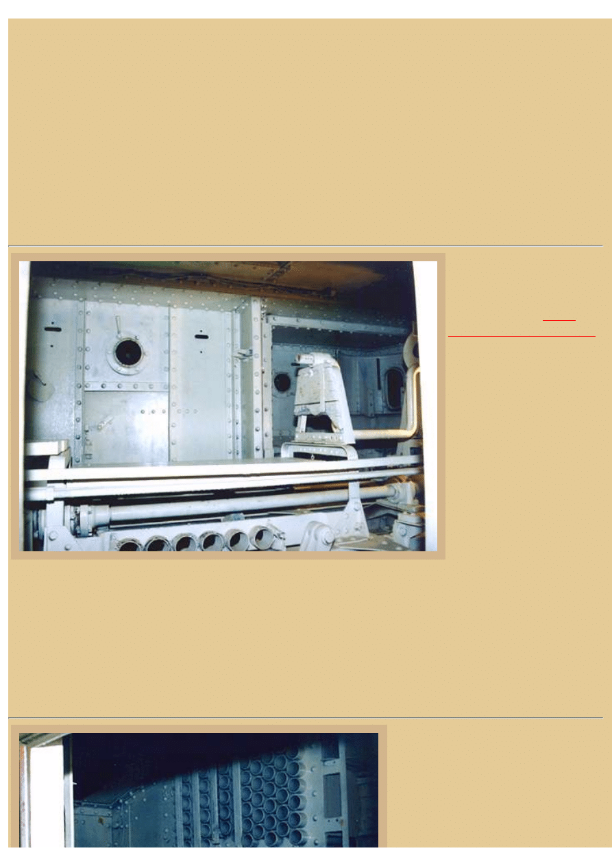
Picture 7:
A view of a Mk. V*
during construction in
the Metropolitan factory
shows a few more
interior details.
Metropolitan Carriage
and Wagon,
Birmingham, started life
in 1845 as Joseph Wright
& Sons, and in 1863
became the Metropolitan
Railway Carriage &
Wagon Company,
builders of mostly
railway cars and
equipment. By 1902 the
company had become
the Metropolitan
Amalgamated Railway
Carriage & Wagon
Company, later
shortened to
Metropolitan Carriage
and Wagon. It was a
natural fit for new tank
building and
file:///H|/Modellismo/AFV%20Interiors/[armor]%20-%20AFV%20Interiors/afvinteriors.hobbyvista.com/mkv/mkv1.html (4 di 7)25/05/2007 16.54.45
file:///H|/Modellismo/AFV%20Interiors/[armor]%20-%20AFV%20Interiors/afvinteriors.hobbyvista.com/mkv/mkv1.html
construction during the Great War, having built large iron and wood railroad cars for many years.
Visible here, toward the rear, are many of the 380 stowage tubes for 6pdr shells. Also visible is the new open side door
located in the additional side plates that are characteristic of the Mk.V*. Notice the stowage bins visible through the side
sponson openings. The gun sponsons would hold 6pdr guns in the "male" version of the tank, or additional machine guns if
the tank was constructed in the "female" form. There were roughly even numbers of both types produced by Metropolitan.
The pipe protruding out the side of the hull is where the epicyclics will be located, and the opening on our side of the pipe will
eventually be covered with louvers for air intakes/exhausts to cool the radiator/engine.
The basic Mk.V* tank weighed around 33 tons, and some of that weight is due to the double wall construction for the track
run that was typical of early British tanks of the time. Although the space was not wasted (ammo and other stowage was
placed there) the additional weight of this steel decreased the potential overall performance of all the early tanks and, added to
the additional length of the Mk. V*, decreased the maximum speed to only 4 mph. The maximum armor thickness was 12mm
(roughly 1/2in) at this time, a small improvement over the Mk.IV.
Picture 8:
This is one of my photographs
of one of the few surviving Mk.
V* tanks, this one is located in
the collection at the
at Ft. Knox, Kentucky. You are
looking forward through the
new right side door of the cargo
area toward the left sponson
(shadows off in the distance).
The 6pdr. guns have been
removed from the sponsons.
Closer to the camera is the
cargo area with the drive shaft
running close to the floor from
the engine at the front to the
gearbox behind. Off to the right
is the starter crank for the
engine, which is mounted even
further off to the right. It took
four men to crank over the
engine while the driver operated a hand-starting magneto switch.
Directly across from us is the opposite door on the left hull side and above that is one of the round ports for a ball-mounted
Hotchkiss machine gun (the ball mount missing). The innovative ball mount seen in British tanks from the late Mk.IV on
greatly improved the firing arc possible with the machine guns (from 60degrees to 90 degrees) and provided added protection
for the crew. This is because the ball mount allowed less bullet splash to enter into the interior; previously the crew fired their
MG's through open ports. This ball MG mount was invented by Mr. Skeens and it became standard production for all AFVs
by the end of the war. The ball mount design would have made Skeens a hero to the tank crews, if only they had known who
he was at the time.
Picture 9:
This is a view of the same Patton Museum
vehicle, but this time looking aft, showing
the 6pdr. ammo storage along the wall in the
rear (as we saw previously in the factory
photograph). There is a similar ammo rack
on the other side of the hull. Also visible
file:///H|/Modellismo/AFV%20Interiors/[armor]%20-%20AFV%20Interiors/afvinteriors.hobbyvista.com/mkv/mkv1.html (5 di 7)25/05/2007 16.54.45

file:///H|/Modellismo/AFV%20Interiors/[armor]%20-%20AFV%20Interiors/afvinteriors.hobbyvista.com/mkv/mkv1.html
here is the large round epicyclic gear
housing (also known as planetary gears)
mounted in the sidewall, and the large
shroud around the fan is visible on this left
side of the tank. There is a second epicyclic
housing on this side of the hull, but instead
of a fan, there is the radiator. The metal
shroud curves down after the fan before
curving up again around the radiator in order
for there to be room above the shroud to
mount a rear-facing MG ball mount on the
rear armor wall. Once power was transferred
from the gearbox to these two epicyclic
gears, chain drives brought power to small
reduction gears, which in turn then powered
the two drive sprockets. All the epicyclic
gears do is convert the high revolutions of
the drive shafts coming from the gearbox
into low revolutions and high torque to drive
the sprockets, due to the size difference of the two meshed gears.
To steer the tank left or right, the driver pulled back the corresponding control (steering) lever, which in turn released a pinion
in the epicyclic gear allowing it to idle and the corresponding track to slow, and eventually, stop. As the track slowed, the tank
would slowly turn in that direction. The driver could make a sharper turn in the same direction by adding some brake pedal
pressure and stopping the track more quickly. Also down near the floor are some of the control rods attached to the driver's
levers and foot pedals up front and stretching all the way back to the gearbox and steering linkages in the rear. Notice the
elevated wooden platform used to stand on by the machine gunners while using their MGs in the weapons ports in the over-
head cupola. You can just imagine the noise and smell inside one of these beasts in action when the machine guns were
rattling, the engine roaring, and an occasional 6pdr firing, all within the echoing confines of this hot, dark, gyrating metal box.
What a nightmare it must have been to work inside one of these tanks.
Picture 10:
A drawing of the left side
drive train from the gearbox
at the lower right to the drive
sprockets at the far left
shows the layout of the
epicyclic gears, the chain
drive, the reduction gear, and
the sprockets. Most of this
was protected inside the
sponson.
Picture 11:
This photo shows the same general
location in the tank again. This time we
have moved up to the right-hand 6pdr
sponson, and we are looking through the
front of the sponson back toward the rear
of the interior. Above can be seen the
gunner's top cupola mentioned earlier
and one of the ports for a rear facing
MG, and to the right is another port for
the left side MG located over the cargo
file:///H|/Modellismo/AFV%20Interiors/[armor]%20-%20AFV%20Interiors/afvinteriors.hobbyvista.com/mkv/mkv1.html (6 di 7)25/05/2007 16.54.45

file:///H|/Modellismo/AFV%20Interiors/[armor]%20-%20AFV%20Interiors/afvinteriors.hobbyvista.com/mkv/mkv1.html
door. Four additional machine guns were
added to the Mk.V series from the
previous Mk.IV, the two in this over-
head cupola "turret" and one in each of
the side sponsons. Again, off in the
distance, you can see storage racks for
ammo, and nearer to us is the engine
starting crank.
To the far left of the photo is the latch
for the door in the sponson we are
looking through; there was a door
located in the rear section of both side
sponsons. The entire 6pdr mount has been removed from this sponson and its absence allows our view. The interiors of these
early vehicles were generally painted white to improve visibility, but they probably did not stay that way for long with hard
use. This particular photograph shows the interior of the Patton vehicle to be yellow, but the color is due to the film
processing and incandescent lighting, not the actual color (white) the museum has painted the interior.
This consludes Part 1. Part 2 will continue or examination of the interior of the Mk.V*.
BACK TO AFV INTERIORS HOME PAGE
(c) 2002, 2003 AFV INTERIORS Web Magazine
file:///H|/Modellismo/AFV%20Interiors/[armor]%20-%20AFV%20Interiors/afvinteriors.hobbyvista.com/mkv/mkv1.html (7 di 7)25/05/2007 16.54.45
file:///H|/Modellismo/AFV%20Interiors/[armor]%20-%20AFV%20Interiors/afvinteriors.hobbyvista.com/mkv/mkv2.html
British Mk.V* Tank, Part 2
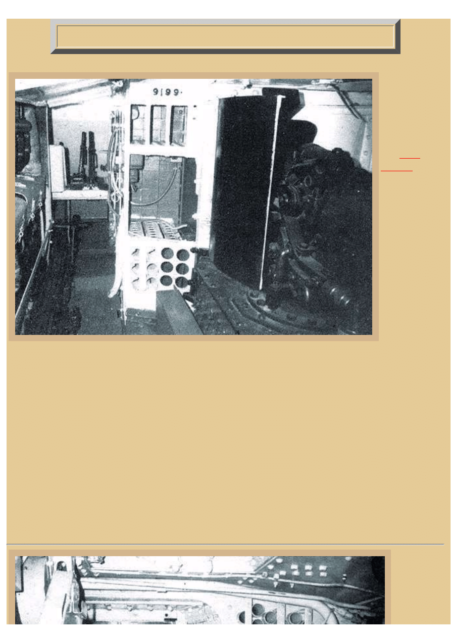
Picture 1:
This is Part 2 of
a two-part series
exploring the
interior of the
British WWI
tank Mk.V*.
This
photo
was taken inside
their preserved
Mk.V tank in
the early 1960's.
The photo
shows the view
looking toward
the front of the
AFV along the
right side of the
hull. You can
see the intact
Ricardo engine
off to our left;
the protective
metal shroud
has a flat hinged cover on this side that has been completely removed to reveal the engine inside. Up forward on the
right are shelves for ammunition and other stores, but the partitions have been lost that would separate the bins for
each MG ammo box.
Up at the very front of the AFV is the elevated crossbeam platform for the driver and front hull machine gunner. We
can see the driver's change speed lever (gearshift) close to his seatback and the forward-reverse lever further to the
right. The driver's right steering lever is mostly hidden by the seatback, except for the very end of the handle. The
driver's seat was just slightly to the right of being directly in front of the engine, while the front gunner's seat to his left
was almost touching the left sponson wall. The driver's seatback was actually touching the front shroud of the engine
and very close to the front armor of the tank. There was not much room for his seat in these tight quarters.
Personal accounts indicate that starting the engine in cold weather required priming of each engine cylinder through
its priming cock, having first warmed the spark plugs (two each cylinder) on a pile of burning cotton waste. When the
engine was really cold, crews are said to have warmed the priming petrol outside the tank by lighting it in a tin. Once
the fuel had warmed, a tight fitting lid was placed over the tin to extinguish the flames and the fuel then used to prime
the engine. Off to the right is a very dark 6pdr and mount that unfortunately does not show up very well in this light.
Picture 2:
This photo
was taken
inside the
same Mk.V
16.54.56
file:///H|/Modellismo/AFV%20Interiors/[armor]%20-%20AFV%20Interiors/afvinteriors.hobbyvista.com/mkv/mkv2.html (1 di 7)25/05/2007

file:///H|/Modellismo/AFV%20Interiors/[armor]%20-%20AFV%20Interiors/afvinteriors.hobbyvista.com/mkv/mkv2.html
vehicle at
Bovington
and shows
the
components
looking
toward the
right side of
the hull from
the left gun
sponson.
Again, the
characteristic
6pdr. ammo
rack is on
the wall near
the rear of
the
compartment,
and the epicyclic gear housing is seen below. We can look across to the right sponson and see the rear door that is
painted a darker shade of paint, and also the ball mounting for the MG.
To our left is the rear of the engine shroud and engine, visible only because this is a short Mk.V, not a Mk.V*. The
ducting on this end of the shroud is the fan exhaust that pulls air surrounding the engine out through louvers in the
ceiling. If this was an extended Mk.V*, we would not see the engine and shroud here, but instead see the additional
hull wall plates directly across from us; the engine would be further off to the left. Up on the ceiling is the radiator
hose leading back toward the radiator, which is out of our view to the right. The roof cupola is just about directly
above us, and the machine gunner's raised wooden platform is at the bottom of the picture.
Picture 3:
This is a well-known photo from the
Imperial War Museum (as many of
these photos are) of tank gunners and
instructors examining the 23cal 6pdr
Hotchkiss naval gun and mount
typically found in male Mk.IV and Mk.
V/Mk.V* tanks. Earlier marks had used
the original longer barreled version of
the naval 6pdr, but its length had
caused problems so this shorter version
was developed especially for these
tanks. Half of the Mk. V* tanks built
were female types, armed only with six
Hotchkiss machine guns, while the
other half were males, armed with two
of these 6pdr naval guns (one in each
side sponson) and four Hotchkiss MGs
in ball mounts. The short 23cal 6pdr
was used in both Mk.IV and Mk.V
tanks, so these photos are applicable to
both marks. There was normally an
eight-man crew in these Mk.V* tanks: commander, driver, two machine gunners, and two 6pdr gunners (male tanks)
16.54.56
file:///H|/Modellismo/AFV%20Interiors/[armor]%20-%20AFV%20Interiors/afvinteriors.hobbyvista.com/mkv/mkv2.html (2 di 7)25/05/2007
file:///H|/Modellismo/AFV%20Interiors/[armor]%20-%20AFV%20Interiors/afvinteriors.hobbyvista.com/mkv/mkv2.html
or 4 total machine gunners (female tanks), and two loaders. There were basic telescopic sights for the main guns and
loopholes and peep slots for the machine guns. Unfortunately, due to the distance the machine gunners stood from
their sights, the field of view outside was extremely limited.
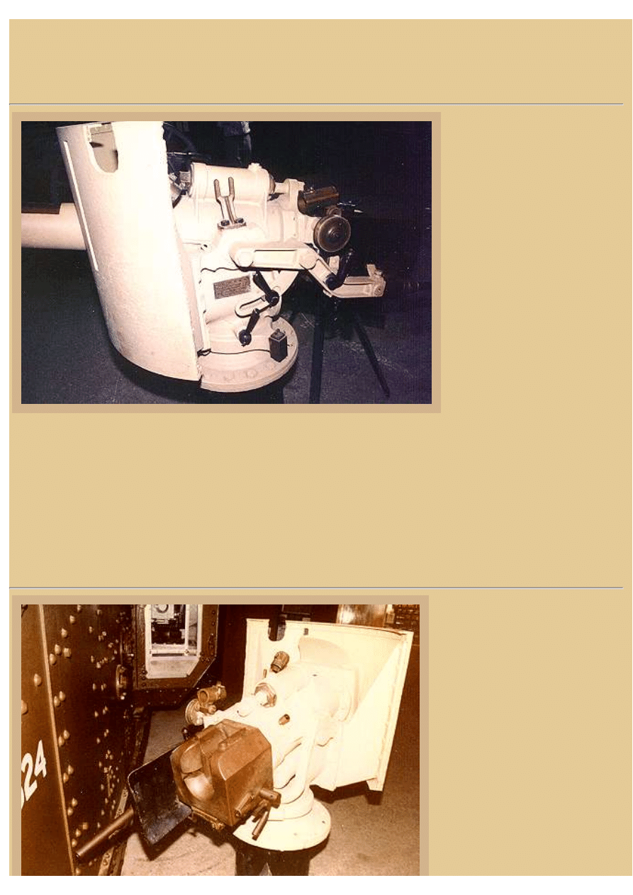
Picture 4:
This is a view of a preserved 6pdr
gun preserved at The Tank
Museum in Bovington, England.
The main recuperator is the
cylinder you see on top, two
recoil springs are mounted
underneath, and the copper
colored breech is mostly lost in
the shadows to the right.
Typically, the gun cradle was
mounted on its pintle on top of an
armored box, which also
contained storage holes for 20 or
so 6pdr. rounds. Approximately
380 of these rounds were carried
inside the Mk.V* and over 7,000
machine gun rounds were also
available, stored in wooden
boxes.
On this left side of the gun mount you can see the elevation and traverse locks and two brackets to hold the telescopic
sight. The bracket at the rear is a cylinder shape and the one at the front, bolted to the mount at its pivot, looks like a
Y. Field of view for these short 6pdr guns was only 20 degrees through the telescope. Range was estimated by eye and
a drum was then adjusted on the side of the mount, which depressed the line of sight in relation to the gun axis. This
gave the necessary additional elevation to compensate for gravity effects on the shot when the telescopic sight was
laid on the target. It was a fairly simple system, but effective enough for these early tanks. The gun had a manual hand
crank for traverse and was elevated by shoulder pad control. We have not been able to find much about the telescopes
used with these 6pdrs. in tanks. If you can shed some light on this subject, we would be eternally grateful....
Picture 5:
This is the right side and breech of
the naval 6pdr. The breech block is
of the vertical falling type and is
worked by the hand crank on the
side of the breech ring. Visible here
is the left recoil shield and aiming
handle (minus its padded grip), and
the cylindrical rear mount for the
telescopic sight is also visible.
There were three types of ammo
that could be carried-- AP, HE and
case shot (called "K-shot") for anti-
personnel work. This was made of a
sheet metal case containing steel
balls and a small bursting charge
inside set to detonate on contact.
16.54.56
file:///H|/Modellismo/AFV%20Interiors/[armor]%20-%20AFV%20Interiors/afvinteriors.hobbyvista.com/mkv/mkv2.html (3 di 7)25/05/2007
file:///H|/Modellismo/AFV%20Interiors/[armor]%20-%20AFV%20Interiors/afvinteriors.hobbyvista.com/mkv/mkv2.html
The AP ammo wasn't developed
until 1918 and was then provided
for the Mk.IVs and Vs that were still in service. It has been written that the sighting telescope had only a slight
magnification, perhaps 2x.
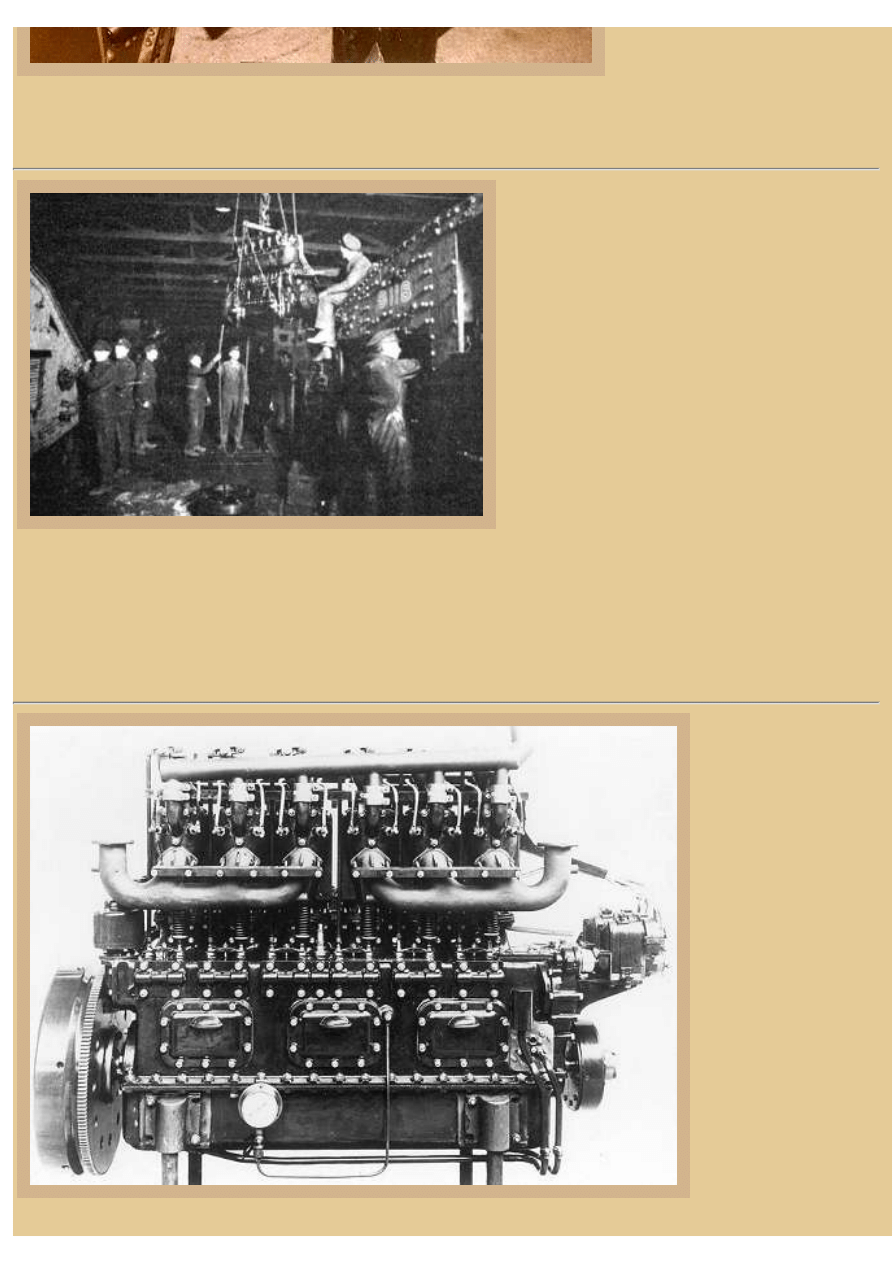
Picture 6:
This photo shows the Ricardo engine designed for
the new tanks, in this case being pulled out of the
vehicle for maintenance. For its time, the Ricardo
was a light-weight and powerful engine, producing
a minimum of 150bhp at 1200 rpm. It was a
straight 6-cylinder type with removable panels on
the crankcase allowing most maintenance to be
performed without having to lift the engine like
this. Twin oil scavenge pumps, crosshead design,
and pressure lubrication helped cut down on oil
smoke in the exhaust which was so prominent with
the Daimler 105hp sleeve-valve gasoline engines
used in earlier Mks. Two carburetors and magnetos
helped to reduce engine faults and the pistons were
lubricated by oil splash. Unfortunately for the
crew, cooling air for the large tube water radiator at
the rear of the vehicle was drawn from outside the tank, rather than being supplied from the interior and then being
blown out which could have cooled the interior air considerably. This made the interior of the Mk.V and V* tanks
hotter and more unbearable than they had to be. And yet, on the whole, the Mk.V was still fairly popular with crews,
primarily due to the improved driving ease of the beast and the fact that the engine was relatively trouble free
compared to earlier designs.
Picture 7:
The Ricardo engine used
in the Mk.V and Mk.V*
was designed by the
gifted engineer Harry
Ricardo, the engine
having to meet difficult
requirements established
by Albert Stern (then
Commissioner for
Mechanical Warfare) for
tank use. The new
engine was required to
develop at least 150hp
and operate at great
angles without burning
oil. Neither aluminum
nor high tensile steel
could be used, due to
their need in other
armaments.
So like the Daimler
16.54.56
file:///H|/Modellismo/AFV%20Interiors/[armor]%20-%20AFV%20Interiors/afvinteriors.hobbyvista.com/mkv/mkv2.html (4 di 7)25/05/2007
file:///H|/Modellismo/AFV%20Interiors/[armor]%20-%20AFV%20Interiors/afvinteriors.hobbyvista.com/mkv/mkv2.html
engine it replaced, Harry Ricardo designed his powerplant as an in-line 6-cylinder type, but he increased the cylinder
capacity by building the engine taller with longer cylinders and subsequent longer throws and displacement. You can
see how the engine is fairly simple in design with its tall exposed cylinders bolted vertically above the long crankcase.
The exhaust valves are all exposed on this right side; the exhaust is routed away via two exhaust pipes, which turned
up and exited through the roof of the Mk.V*. Also clearly visible in this photo are three of the access plates along the
engine case that simplified repair and eliminated the need to remove the engine for minor maintenance problems. The
large geared flywheel is to the left (rear of the engine) and you can see the dual magnetos at the right.
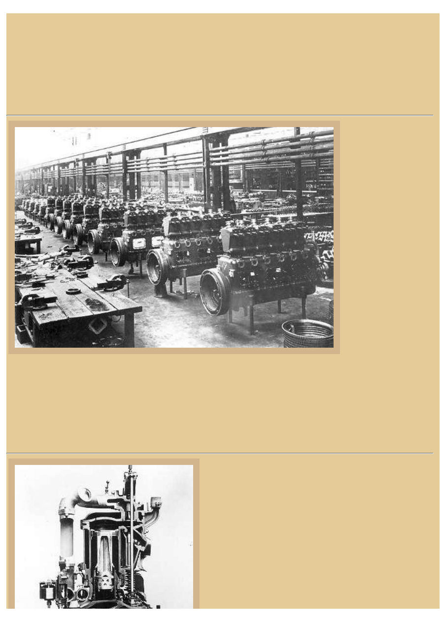
Picture 8:
This photo shows 225 B.
H.P. Ricardo tank
engines under
construction at Messrs.
Gardner's Works, in
Manchester, during
World War I. Sir Harry
Ricardo was born in
London in 1885 and was
educated at Rugby and
Cambridge where he
studied at Trinity
College. Harry Ricardo
certainly knew engines,
and the one he designed
to be used in the Mk.V*
employed four
horizontal valves
operated by push rods
and bell cranks,
something no one else
had ever tried. They also introduced a new design known as a crosshead piston, and the results were so successful that
Ricardo Consulting Engineers produced around 8000 of these engines for tanks, with many more powering generators
in workshops, hospitals, and military camps. Some were even used in railway shunting locomotives and in marine
propulsion. The success of the engine venture led to Harry Ricardo buying the land and setting up a laboratory on its
present company site in 1919. Many other successes were credited to Ricardo over the years, including the Octane
Rating Scale. Harry Ricardo invented a unique variable compression ratio engine dedicated to fuels research, and that
is what led him to devise the fuel rating index known today as the Octane Rating.
Picture 9:
So what is a crosshead piston design anyway? In short,
crosshead-type pistons can use the lower side of the piston
crown as a supercharger, and the crown of the piston is
therefore isolated from the crankcase chamber and very
effective oil control can be maintained with little visible
exhaust smoke. The word "crosshead" comes from earlier steam
engine designs were a crosshead connected a steam engine's
piston to the rotating wheel, allowing movement from the up
and down moving piston to be changed to a circular movement
to rotate drive wheels. Sir Ricardo used this principle by
attaching a pivoting crosshead to connect the piston rod to the
connecting rod of his engine. Crosshead piston rod assemblies
16.54.56
file:///H|/Modellismo/AFV%20Interiors/[armor]%20-%20AFV%20Interiors/afvinteriors.hobbyvista.com/mkv/mkv2.html (5 di 7)25/05/2007
file:///H|/Modellismo/AFV%20Interiors/[armor]%20-%20AFV%20Interiors/afvinteriors.hobbyvista.com/mkv/mkv2.html
transmit the reciprocating piston motion into rotational
crankshaft motion, and since the vertical piston motion
provides no side thrust on the cylinder walls, the rings last
longer and there is very little oil burned, producing very little if
any smoke during the running of the engine.
This is a sectional model of a Ricardo tank engine and shows
some of the features of this engine. Unfortunately, the
crosshead connections of the piston rods are lost down behind
the handwheel that rotated the crankshaft in this working
model. But you can see that both the intakes and exhaust valves
are on the same side of the combustion chamber, intake from
the top and exhaust from the sides.
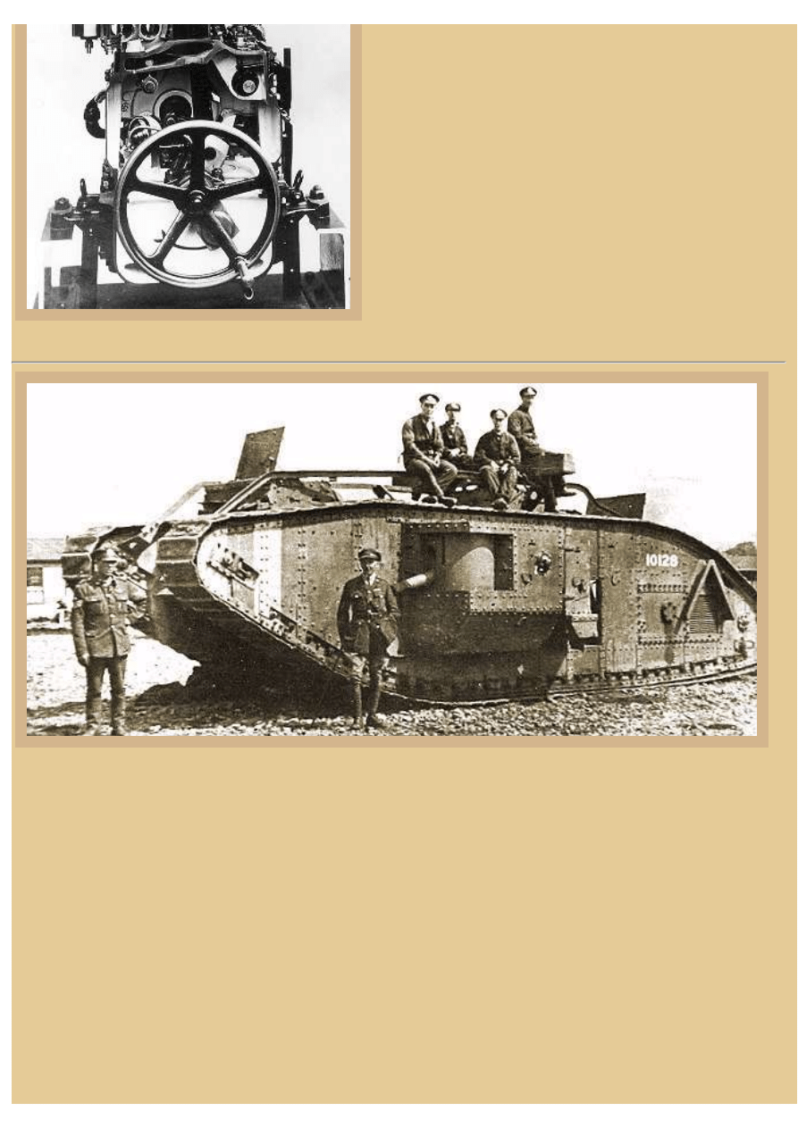
Picture 10:
In this IWM photograph, notice the front hull machine gunner's open over-head hatch (which the driver could also
use) and another other open roof hatch further back on this tank. Many British tanks were lost due to the mud during
combat at Messines, so in the summer of 1917 rails were added across the top of tanks like this Mk.V* for attachment
of an unditching beam. When the tank became bogged down in mud, the beam could be chained to the tracks on the
roof, and the beam would be pulled down the front and underneath, where the additional traction it provided might
assist the tank to extract itself. The rear roof hatch was helpful in getting access to the beam to attach the chains and so
were the two hatches in the roof turret. Recall that there are no track rollers along the top of the track run; the tracks
slide along rails until they drop over the front of the tank. The sliding and screeching of the track shoes along the roof
of the vehicle probably added considerably to the noise level inside.
Unfortunately, because the British Home Office insisted on using the same Ricardo engines in the larger Mk.V* as
were fitted in the Mk.V tanks, the lengthened vehicles were under-powered and difficult to steer with so much track
on the ground. But, the Mk.V* design was a further step in the right direction of armored vehicle design. It provided
increased armor protection, a simplified steering system for one-man driving, and an armored troop/cargo carrier to
accompany the tank corps, eventually leading to the development of armored personnel carriers in future years. Notice
the red-white-red recognition markings on the front horns of the tank. These were used to identify British tanks from
16.54.56
file:///H|/Modellismo/AFV%20Interiors/[armor]%20-%20AFV%20Interiors/afvinteriors.hobbyvista.com/mkv/mkv2.html (6 di 7)25/05/2007

file:///H|/Modellismo/AFV%20Interiors/[armor]%20-%20AFV%20Interiors/afvinteriors.hobbyvista.com/mkv/mkv2.html
those that had been captured and were in use by the Germans. The US 301st Tank Battalion also used a similar
marking system, but it may have been oriented to identifying battalions and the order of colors changed accordingly.
With so few available documents about the interior of the Mk.V* tanks, and with only a few surviving vehicles, there
is very little in the way of reference material available about these fascinating AFVs. Should you have additional
information concerning the interior of these vehicles, please do not hesitate to contact us and we will add appropriate
information to these web pages as time goes by. I am grateful to the Ricardo archives for use of their engine
photographs. Except where indicated, the bulk of the images in these pages originated from the library archives of the
Tank Museum and the Imperial War Museum, both in England.
BACK TO AFV INTERIORS HOME PAGE
(c) 2002, 2003 AFV INTERIORS Web Magazine
16.54.56
file:///H|/Modellismo/AFV%20Interiors/[armor]%20-%20AFV%20Interiors/afvinteriors.hobbyvista.com/mkv/mkv2.html (7 di 7)25/05/2007
Document Outline
Wyszukiwarka
Podobne podstrony:
AFV Interiors British Medium Tank Mk I & Mk II
AFV Interiors Water Buffalo
Afv Interiors Isu 152
AFV Interiors CV 33 35
AFV Interiors German AFV Radio Equipment In WWII
AFV Interiors M1A2 Abrams
AFV Interiors Czech Light Tank, LT vz 38, Pz Kpfw 38(t)
AFV Interiors Leopard 2
Afv Interiors Daimler Scout Car
AFV Interiors Otter
AFV Interiors B1 bis
AFV Interiors Marder III
AFV Interiors M113 Toa
AFV Interiors Fahrpanzer
AFV Interiors Semovente Da 75 18
AFV Interiors LVT
AFV Interiors IS 2
AFV Interiors Flakpanzer 38t
Afv Interiors Medium Tank Mark A whippet
więcej podobnych podstron