file:///H|/Modellismo/AFV%20Interiors/[armor]%20-%20AFV%20Interiors/afvinteriors.hobbyvista.com/rads/germrads.html
German AFV Radio Equipment in
WWII
Picture 1:
German World War II armored vehicle
radio sets were typically composed of one
or more radio components that were cabled
together. The receiver and the transmitter
were generally in separate cases, and both
components had to be included in the set if
the radio could both send and receive
messages. The radio component boxes in a
typical set might include a transmitter
("Sender"), a receiver ("Empfanger"),
power transformers ("Umformer"), and any
of a number of accessories, and each
component was usually given a shortened
letter designation for that type. A
transmitter could be cabled to different
receivers in a number of ways, depending
on the combat requirements of the time.
This general radio design created a very
flexible, but confusing, system of radio
component combinations that might be
found inside German armored vehicles.
Once component boxes were combined into a radio set, the name of the set was typically designated by
the letters "Fu" (short for "Funk", or radio) or "FuG" (short for "Funk sprech Gerate", or radio speech
device) followed by a number. I normally use the Fu designation because it is easier to type and
because the FuG is more typically used for designating aircraft radio sets. So, for example, the primary
radio set used in German panzers for the majority of the war was the Fu.5. This set included a 10watt
transmitter (designated "10 W.S.c.", with the name printed on the face of the unit), an ultra short wave
receiver "e" ("UKw.E.e."), a power transformer for each of the two component boxes, and various
accessories, such as headphones, microphones, a key pad for Morse Code, etc. The only major
exception to this simple Fu. nomenclature system is the common voice transmitter radio set used in
many combat support vehicles. This set was known as the Fu.Spr.f. and used in self-propelled guns,
armored cars, and most halftracks. Below is a table listing the most common radio sets and the vehicles
they were typically mounted in.
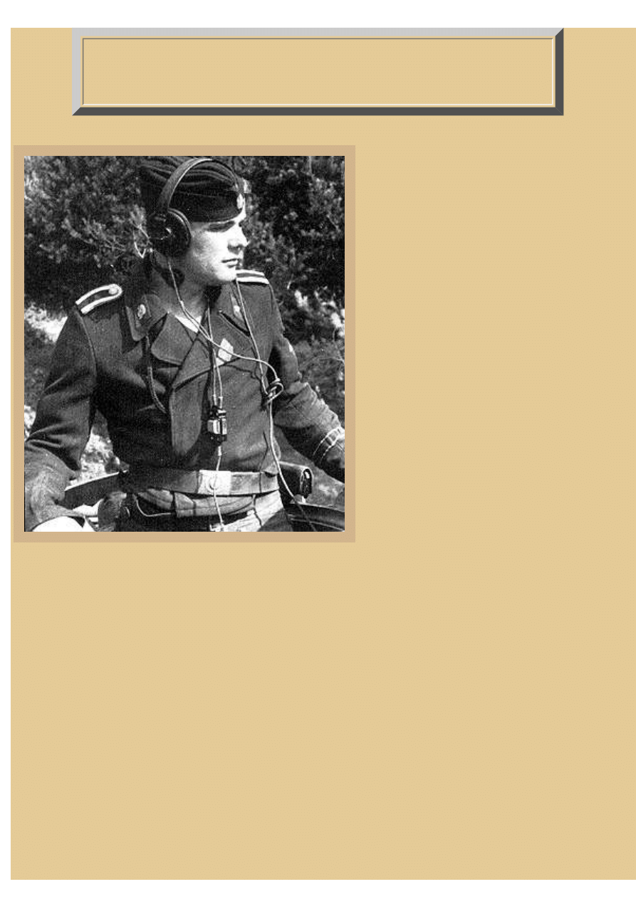
The Totenkopf tank commander illustrated here is wearing the typical German armored vehicle radio
communications gear. This includes headphones, a throat microphone (Kehlkopf), and the
microphone's on/off control switch hanging on his chest. Most German tank radio sets required a
separate intercom switching device ("Bordsprech Schaltkasten"), which was a small box normally
file:///H|/Modellismo/AFV%20Interiors/[armor]%20-%20AF...teriors/afvinteriors.hobbyvista.com/rads/germrads.html (1 di 10)25/05/2007 17.06.05

file:///H|/Modellismo/AFV%20Interiors/[armor]%20-%20AFV%20Interiors/afvinteriors.hobbyvista.com/rads/germrads.html
operated by the radio operator in the right front seat. This intercom system allowed the tankers inside
to talk with one another, except, in most cases, the hard-working loader who was not provided with
any radio equipment.
COMMON RADIO SETS USED IN GERMAN WWII AFVs
Vehicle
Radio Set
Unit commander's tank
Fu.5 and Fu.8, or Fu.5 and Fu.7
Squad leader and typical tank
Fu.5 and Fu.2, or Fu.5 only
Subordinate armor vehicles
Fu.2 (receiver only)
Assault guns, armor formations
Fu.5 and Fu.4, or Fu.8 and Fu.4 and Fu.Spr.
f.
Assault guns artillery
Fu.8 and Fu.16 and Fu.15, or Fu.16 and
Fu.15, or Fu.16 only
Armored OP artillery vehicles
Fu.8 and Fu.4, or Fu.8 and Fu.4 and Fu.Spr.
f.
SP antitank guns (light and med)
Fu.5 and Fu.8, or Fu.5 only
SP antitank guns (heavy chassis)
Fu.5 and Fu.8, or Fu.5 and Fu.7, or Fu.5
and Fu.2
Antitank assault guns
Fu.5 and Fu.8, or Fu.5 only
Lynx (recon)
Fu.12 and Fu.Spr.f or Fu.Spr.f. only
Antiaircraft tanks (Flakpanzer)
Fu.5 or Fu.2
SP heavy infantry gun
Fu.16
Wasp and Bumble Bee and Marder
Fu.Spr.f.
Armored cars (except 8 wheeled vehicles)
and semi-tracked vehicles with armament
Fu.Spr.f.
Armored cars
Fu.12 and Fu.Spr.f.
8 wheeled armored cars
Fu.12 and Fu.Spr.f. or Fu.Spr.f. only
Early in the war, the typical German panzer was provided only with a receiver, generally a Fu.2, and
the crew could therefore not transmit any messages, they could only receive them. Only later did most
tanks receive the Fu.5 set with both transmitter and receiver included. So, what component boxes were
actually included in each radio set? If we can identify the component boxes, we can then identify the
radio set by knowing which components are included in each radio set. Below is a chart with the radio
component boxes for each of the main radio sets used in German WWII AFVs that I have seen inside
panzers over the years. Again, the letter designations in parenthesis are usually printed on a label on
the front face of the radio component boxes, and also sometimes on a cover plate that protected the
unit when not in use. I've also included the antenna length and type that was used.
file:///H|/Modellismo/AFV%20Interiors/[armor]%20-%20AF...teriors/afvinteriors.hobbyvista.com/rads/germrads.html (2 di 10)25/05/2007 17.06.05

file:///H|/Modellismo/AFV%20Interiors/[armor]%20-%20AFV%20Interiors/afvinteriors.hobbyvista.com/rads/germrads.html
COMMON RADIO SET COMPONENTS
Radio Set
Components
Aerial
Comment
Fu.2
Ultra short wave receiver
"e" (Ukw.E.e)
2 meter rod
receiver only,
standard tank set
Fu.4
Med. wave receiver "c" (MW.
E.c)
2 meter rod
receiver only,
standard artillery
set
Fu.5
10 watt trans. (10 W.S.c.)
and Ultra short wave receiver
"e" (UKw.E.e)
2 meter rod
standard squad
leader's tank radio
set
Fu.7
20 watt trans (20 W.S.d)
2 meter rod
ground-air coord
set
Fu.8
30 watt trans "a" (30 W.S.a)
and Med. wave receiver
"c" (Mw.E.c)
roof aerial
8 meter winch
mast and star
aerial increased
range
Fu.12
80 watt trans. "a" (80 W.S.a)
and Med. wave receiver
"c" (Mw.E.c)
roof aerial
8 meter winch
mast and star
aerial increased
range
Fu.15
Ultra short wave receiver
"h" (UKw.E.h)
2 meter rod
receiver only,
Sturmartillerie
Fu.16
10 watt trans "h" (10 W.S.h)
and Ultra short wave receiver
"h" (UKw.E.h)
2 meter rod
sim. to Fu.5 but
different
frequency range
Let's test the chart system now with an example. If we are interested to know what radio was used in a
typical 8-wheeled armored car, we can refer to the above reference tables and find that these vehicles
most often carried an intervehicle voice set Fu.Spr.f., and sometimes an additional radio set, like a
Fu.12 (which would require two more component boxes, an 80 W.S.a and a Mw.E.c.). As far as
receiver and transmitter identification, the component cases and their faces were very similar in
appearance on the outside, as long as they were of the same type. Most of the German cast metal radio
cases seem to have came from the manufacturers painted black, and the radios had a lighter gray face
plate with black knobs. But, you will also find black painted radio face plates, and both faces and cases
that have been painted the primary interior vehicle color, depending on the vehicle (open topped AFVs
had a greater chance of repainted radios). I suspect radios were also repaired fairly frequently in the
field, and the faces and cases might be repainted at that time.
file:///H|/Modellismo/AFV%20Interiors/[armor]%20-%20AF...teriors/afvinteriors.hobbyvista.com/rads/germrads.html (3 di 10)25/05/2007 17.06.05
file:///H|/Modellismo/AFV%20Interiors/[armor]%20-%20AFV%20Interiors/afvinteriors.hobbyvista.com/rads/germrads.html
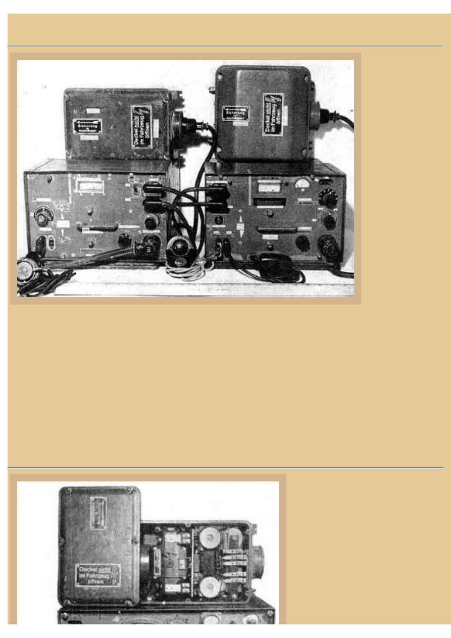
Picture 2:
This is the most
common panzer
radio set in use by
mid-war, the
Fu.5. The
receiver, Ukw.E.
e., is on the left
and the
transmitter, 10 W.
S.c., is on the
right, with the
power
transformers
(sometimes called
"dynamotors") for
each component
sitting on top of
the cases. The
transformers were
necessary to
convert the vehicle battery voltage to that necessary for the radios. Notice how cables connect the
receiver and transmitter together, running from the right side of the receiver to the left side of the
transmitter. Typically, if the radio set was mounted on a single shelf and the two cases placed side by
side like this, the receiver was placed on the left and the transmitter on the right. As I mentioned
earlier, there was a power transformer required for each radio receiver or transmitter, and these
transformers were typically mounted below or to the side of the cases, but always very close by. Also
in this image you can see on the right, sitting on the table, a black teletype (Morse) key, while in the
center on the table is a voice microphone, and on the far left a set of headphones. Each of these
transmitters/receivers weighed only around 20lbs, which was a very reasonable weight for a radio at
this time.
Picture 3:
Here's the 30 W.S.a. transmitter
found in a Fu.8 set, these sets
typically mounted in Sturmartillerie
vehicles (StuG assault guns, for
instance). If you were examining a
StuG III with a Fu.8 set, you would
expect to find one of these
transmitter boxes sitting next to a
Mw.E.c. receiver, the second part
of the Fu.8 set. The 30 W.S.a.
file:///H|/Modellismo/AFV%20Interiors/[armor]%20-%20AF...teriors/afvinteriors.hobbyvista.com/rads/germrads.html (4 di 10)25/05/2007 17.06.05
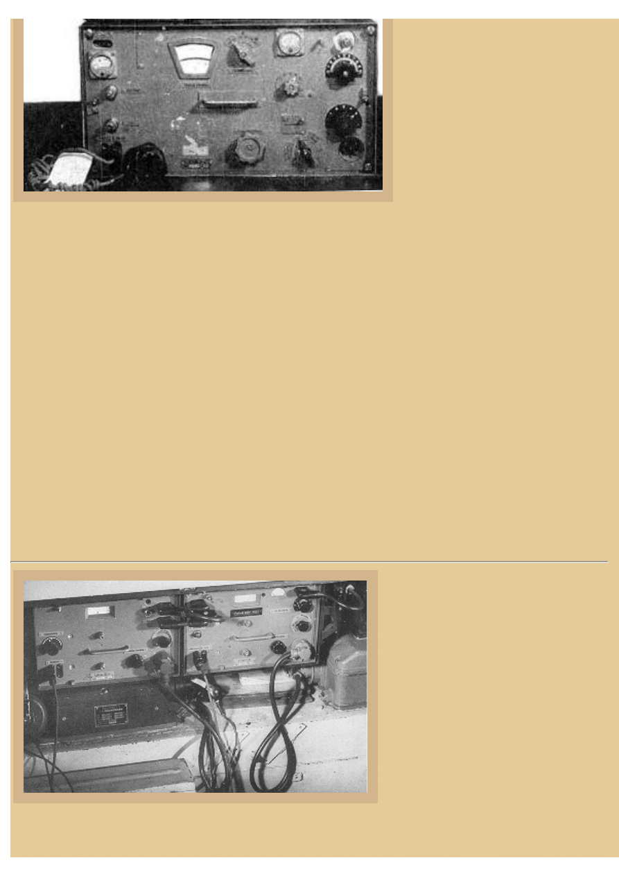
file:///H|/Modellismo/AFV%20Interiors/[armor]%20-%20AFV%20Interiors/afvinteriors.hobbyvista.com/rads/germrads.html
transmitter was also used in
commander's tanks and SP antitank
gun vehicles, particularly in signal
troop units that were required to
stay in communication with their
infantry assets. Like the Fu.5 sets,
the Fu.8 set was capable of
transmitting both
"Telegraphie" (telegraph key, also
known as CW or Morse Code) and
"Telefonie" (voice) amplitude-
modulated (AM) signals. If these vehicles were stationary and were equipped with a frame roof aerial,
the 30 W.S.a. transmitter had a voice range of over 15km. This could be doubled with the use of a big
9-meter winch mast with star aerial on top. The 30 W.S.a. transmitter had 6 tubes inside and was
rugged and extremely well constructed.
Looking at the front of the unit, the sidetone (speaker) cable was connected to the upper left corner
post mount, while the two receptacles on the left of the face are for the receiver antenna binding post
and ground. The two bottom-left receptacles are for the key and microphone leads and you can see that
they are both connected. At the upper right of the radio face is the post for the antenna attachment,
while the bottom right connection is for power input from the dynamotor (transformer). The
transformer is shown above the transmitter with the cover removed to illustrate its internal
components. One of the cover screws has been left in place and the cover simply pivoted open. The
decal on the cover reads "Deckel nicht im Fahrzeug offnen", which means something like "Do not
open covers in the vehicle". This makes sense, as the unit produced a lot of current and it could be a
shocking experience if you happened to touch something inside the box that you shouldn't while the
juice was still on! The transformer provided 12volts at 2.7amps for the filaments, and 400volts for the
plate supply. If you know about such things, you can also see both the starting relay and noise filter
components inside the box.
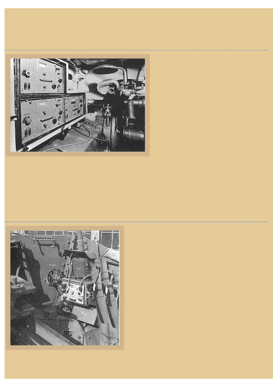
Picture 4:
This is a Ukw.E.h. receiver (left), next
to a 10 W.S.h. transmitter-- combined
they make up a Fu.16 radio set. This
set looks almost exactly like the Fu.5
set-- indeed the cases and controls are
almost identical except for the ID
label on the radio faces and frequency
range markings on the dials. The
major difference between these two
sets was the difference in frequency
bands. Combat tank units and support/
assault/artillery units were required to
use different frequency ranges in order
to keep from interfering with one another-- tanks normally used 27.2 to 33.3 mc, while support
file:///H|/Modellismo/AFV%20Interiors/[armor]%20-%20AF...teriors/afvinteriors.hobbyvista.com/rads/germrads.html (5 di 10)25/05/2007 17.06.05
file:///H|/Modellismo/AFV%20Interiors/[armor]%20-%20AFV%20Interiors/afvinteriors.hobbyvista.com/rads/germrads.html
infantry vehicles used 23 to 24.95 mc. Most likely, this StuG III was part of an assault gun artillery
unit that was supporting an infantry battalion.
Remember that there are some vehicles that will have different radio sets aboard than you would
expect (tanks that were used as forward artillery observation vehicles, for instance) and you cannot
determine what radio set resides inside a vehicle by the type of antenna that is mounted on the vehicle.
Also notice that in this StuG III, one of the power transformers (EUa2) is mounted below the receiver.
The transmitter's transformer (U.10a) is sitting off to the right and obviously is much thicker. It is
connected to the lower right corner of the transmitter. The headphones are barely visible, hanging up at
the far left side of the photo.
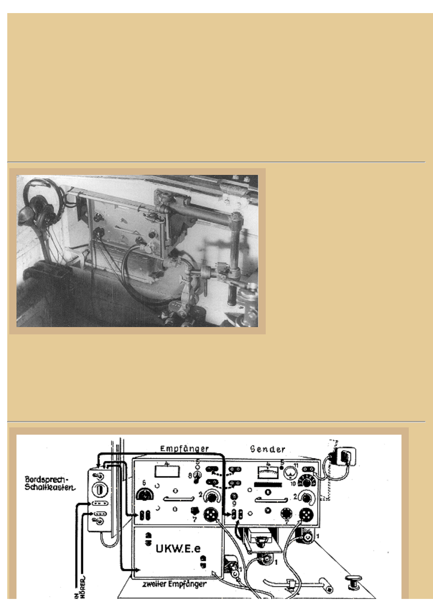
Picture 5:
This same StuG III vehicle also had
an additional Ukw.E.h. receiver
(Fu.15 when it's all alone like this) on
the opposite (right) wall of the hull.
By now you can probably figure out
the general location of the cables and
how they connected. Notice the
headphones hanging at the left, next
to a more primitive communication
device, a speaking tube, that was also
used for inter-vehicle
communications. I find this a
particularly interesting contrast of the
new and old (new at least for the 1940's). The use of a Fu.15 and Fu.16 in the same vehicle might
indicate that this was a platoon leader's vehicle-- he was required to communicate with his own platoon
assets as well as receive orders from upper levels of command on another wave length (thus the need
for the second receiver). All StuG IIIE vehicles had a pannier added on the right sponson just for this
extra Ukw.E.h. receiver.
file:///H|/Modellismo/AFV%20Interiors/[armor]%20-%20AF...teriors/afvinteriors.hobbyvista.com/rads/germrads.html (6 di 10)25/05/2007 17.06.05
file:///H|/Modellismo/AFV%20Interiors/[armor]%20-%20AFV%20Interiors/afvinteriors.hobbyvista.com/rads/germrads.html
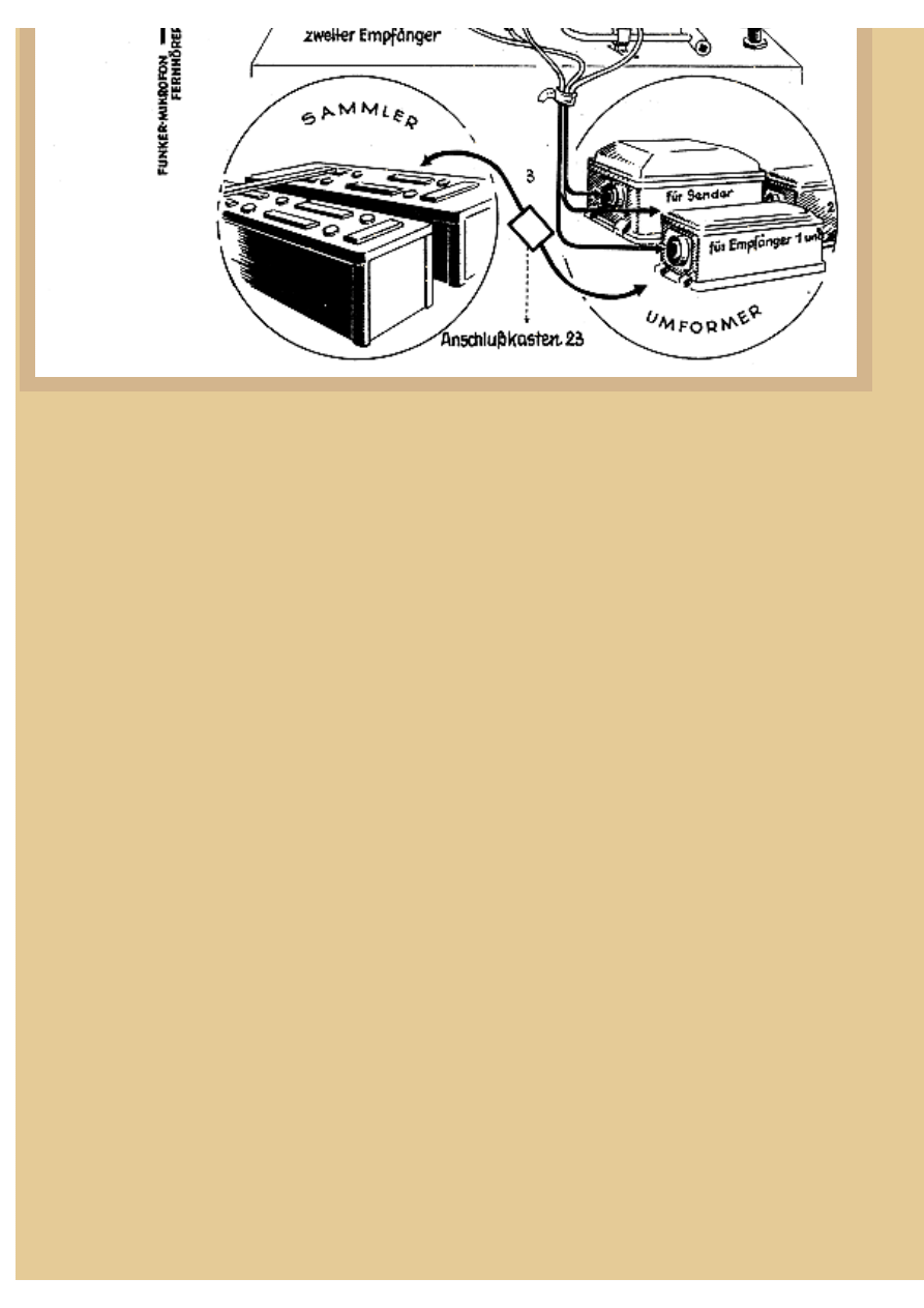
Picture 6:
From the "Tigerfibel" for Tiger I crews comes this drawing of the principal radio set in that tank, the
radios being mounted in a sturdy bracket hanging from the roof and located between the driver and
hull machine gunner, just above the transmission. On the top shelf of the bracket unit is a Fu.5 set
again, with the UKw.E.e. receiver on the left and the 10watt W.S.c. transmitter on the right. In
addition, there is another receiver below the first (another Fu.2 box), this time with its cover shown in
place.
There is a telegraph key on a small shelf below the transmitter; remember these radio sets could send
both voice and key transmissions. Morse Code key transmissions traveled farther over the air, but, of
course, they were a bit slower to send, transcribe, and therefore understand. A small nut wrench is also
shown stored below the radios; it was used to connect wire leads to the screw connectors on the front
of the radios. As we've see here, each of these steel radio cases had attachments for a protective cover,
and on occasion you may see a vehicle with all or some of the covers in place, particularly if the tank
and radio were not active. Most of the covers were held in place with clips on each side of the case, but
later in the war they fit down into the case and were held on by a few thumb screws. The protective
cover is usually stenciled with the radio type, which you will also find stamped on the faceplate of the
radio. Many previously published pictures of Pz.III and IV interiors show the 10 W.S.c. transmitter
mounted forward of the hull machine gunner with the protective cover in place. You will also usually
see a small shelf to the lower right of the transmitter where the telegraph key is stowed, in a similar
location to this drawing of the Tiger I set.
Notice a few details of the installation. First, the common antenna lead is at the upper right, attached to
the tank ceiling. Second, notice that there are three power transformers, one for each radio case. Notice
also the Bordsprech Schaltkasten (intercom box) at the upper left, the radio operator's control for the
intercom inside the tank. Along with the controls, there are two receptacles on the face of this intercom
box Nr.24, one for the radio operator's headset and one for his throat microphone. Cables from the top
of this box lead to the radio boxes while other cables on the bottom lead to the commander and driver's
smaller radio connection boxes, located near their positions. And lastly, notice that the three
transformers are not mounted in the shelf bracket with the radios. It can sometimes be a bit of a
challenge to locate the transformers in photographs of German AFV interiors, but they are usually
someplace near the rack, or to the right and behind the radio operator in a tank, and secured in place on
their own unique mounting racks, not seen here. These racks come complete with power connectors so
file:///H|/Modellismo/AFV%20Interiors/[armor]%20-%20AF...teriors/afvinteriors.hobbyvista.com/rads/germrads.html (7 di 10)25/05/2007 17.06.05
file:///H|/Modellismo/AFV%20Interiors/[armor]%20-%20AFV%20Interiors/afvinteriors.hobbyvista.com/rads/germrads.html
the transformers just plug into the rack. Each transformer rack can be connected to another one in a
series, so you only require one cable from the vehicle power source (usually the batteries) to operate a
number of transformers for your radio sets.
Picture 7:
Here is the radio setup for a platoon or
company commander in a Panther A. Look
familiar? There is the now familiar Fu.5 set
on the bottom shelf, with an additional Ukw.
E.e. receiver sitting up on the top, just like
we saw in the previous illustration of the
Tiger I setup, but with top and bottom
shelves reversed. In this illustration the
interconnecting wiring between the
component boxes has been removed,
providing us with a much cleaner looking
installation than would normally be the case
during actual operation. Most combat tank
platoon and company commanders would have a setup in their vehicles like this, regardless of which
vehicle it was mounted inside (tank, halftrack, truck, etc.). The Morse key and other accessories would
be carried on the empty self up on the right, or in a storage box, and in this same area you can barely
make out the lead and connection for the antenna mounted on the roof. This is also a nice photo
reference for the hull machine gun ball mount in the Panther A, along with its monocular sight and
head pad.
Picture 8:
This is the only radio set typically carried in a Marder
III anti-tank gun. It is the small intervehicle radio set I
mentioned earlier, the 8 watt Fu.Spr.f., as you will find
in the radio chart above for Marder SP guns. The wire
at the upper right of the face panel leads out to the
antenna that is mounted above. The large wire at the
lower left leads, in this application, to the Fu.Z.
transformer box. The cables from the upper left lead
over to the microphones, and just below this plug is
another one for the loudspeaker/headphones. You can
see the tangle of microphone and headset wires
hanging on the bracket to the left, and also the speaker,
laying on the gun mount in the shadows below.
Although the radio case is still painted black here, the
special bracket for the radio has been painted the
interior paint color of the vehicle and the bright
sunlight makes the radio face seem much lighter than the normal gray shade. This particular radio
support bracket will turn up often in your examinations of German AFV interiors, especially in
file:///H|/Modellismo/AFV%20Interiors/[armor]%20-%20AF...teriors/afvinteriors.hobbyvista.com/rads/germrads.html (8 di 10)25/05/2007 17.06.05
file:///H|/Modellismo/AFV%20Interiors/[armor]%20-%20AFV%20Interiors/afvinteriors.hobbyvista.com/rads/germrads.html
museum vehicles where the radio is missing, and the bracket mount is only used for the Fu.Spr.f. radio.
Once again, this is an amplitude modulation (AM) radio, as were most German WWII AFV radios, and
the antenna type was the typical 6.5ft (2meter) rod. There were seven radio tubes crammed into the
little radio box, and its range was approximately 3.5 miles, normally enough for this type of vehicle.
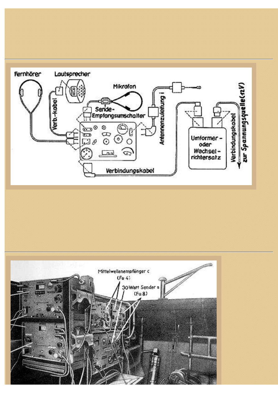
Picture 9:
Here is a schematic for the Fu.Spr.f. radio, providing us with some additional information about the
connections on the face. The headphones, speaker, and throat microphone connect at the upper left
corner, and the power at the lower left corner. Up at the right corner is the connection for the antenna.
Off to the right in the drawing is the transformer with its hookup to the vehicle batteries, usually
12volt. "Spannungsquelle" means voltage source.
Picture 10:
To illustrate just
how messy this
whole German
AFV radio
business can get,
here is a picture
from the operator's
manual for a Sd.
Kfz. 251/3
Funkpanzerwagen.
This was one of
the larger German
halftracks that was
specifically
file:///H|/Modellismo/AFV%20Interiors/[armor]%20-%20AF...teriors/afvinteriors.hobbyvista.com/rads/germrads.html (9 di 10)25/05/2007 17.06.05

file:///H|/Modellismo/AFV%20Interiors/[armor]%20-%20AFV%20Interiors/afvinteriors.hobbyvista.com/rads/germrads.html
configured as a
command vehicle.
The two units on
the upper right
shelf are identified
as Fu.4 units (Mw.
E.c.). And, as you can see, the big 30 W.S.a. on the bottom shelf, combined with one of the upper Fu.4
units, makes up a Fu.8 set. Are you still with us?
The upper unit on this end rack (to the left) looks like a transmitter Ukw.E.e., and the lower unit is
probably a receiver 10 W.S.c., which when combined would make up a Fu.5 radio set. So, the question
is, what's this vehicle communicating with? As you know, the Fu.5 was used for armored unit
communications, and the Fu.8 for assault/antitank unit communications. So,a good guess would be that
this is a commander's vehicle for a large armored unit of some kind that had to communicate with both
armor and infantry assets, probably on the divisional level (due to the two Fu.4 sets on board). These
vehicles equipped with this type of radio setup were generically called "Kommando Panzerwagen", or
command armored vehicles.
Much of the radio data information in this page comes from an excellent reference work titled "U.S.
War Department Handbook on German Military Forces", which includes a short introduction by
Stephen E. Ambrose. The book is a compilation of previously published War Department documents,
and has been republished by Louisiana State University Press. It is chock-full of very useful, although
sometimes inaccurate, material and it is highly recommended. Additional illustrations used in the page
come from the Bundesarchiv and US Army photo files. This web page is a revision of an earlier AFV
INTERIORS page, previously published in 1997.
BACK TO AFV INTERIORS HOME PAGE
(c) 2002, 2003 AFV INTERIORS Web Magazine
file:///H|/Modellismo/AFV%20Interiors/[armor]%20-%20AF...teriors/afvinteriors.hobbyvista.com/rads/germrads.html (10 di 10)25/05/2007 17.06.05
Document Outline
Wyszukiwarka
Podobne podstrony:
German only, language rule in German schools
FORTYFIKACJE (GERMANY) INVENTAR DER FESTUNGEN IN POLEN
Hitler and Nazi Germany (Questions and Analysis in History)
Our Chances Were Zero The Daring Escape by Two German POW s from India in 1942 by Rolf Magener
(Ebook German) Schwarzpulver (43 Mischungen In 9 Tabellen)
AFV Interiors Water Buffalo
Afv Interiors Isu 152
AFV Interiors CV 33 35
AFV Interiors M1A2 Abrams
AFV Interiors British Medium Tank Mk I & Mk II
AFV Interiors Czech Light Tank, LT vz 38, Pz Kpfw 38(t)
AFV Interiors Leopard 2
Afv Interiors Daimler Scout Car
AFV Interiors Otter
AFV Interiors B1 bis
Afv Interiors Mk V
AFV Interiors Marder III
AFV Interiors M113 Toa
AFV Interiors Fahrpanzer
więcej podobnych podstron