file:///H|/Modellismo/AFV%20Interiors/[armor]%20-%20AFV%20Interiors/afvinteriors.hobbyvista.com/m113toa/m113toa1.html
M113-based Mortar Carriers, Part 1,
Revised April 26, 2002
Picture 1:
Some time
ago, Cesar
de los
Bueis
from
Spain sent
us some
interesting
images of
a vehicle
he had
spotted
and
photographed.
Known to
him as the
M113
TOA
120mm
Mortar
Carrier, I
thought it
was about time for us to take a closer look at this particular vehicle. I also thought it might be interesting
to compare it to M113-based mortar carriers used in the USA over the past few years, including the M125
81mm Mortar Carrier, the M106 107mm Mortar Carrier, and the M1064 120mm Mortar Carrier. We will
first explore the Spanish 120mm carrier in Part 1, and then in Part 2 we'll take a quick look inside the
three main US carrier vehicles.
The basic chassis for this Spanish vehicle is a FMC M113A1 and it has the typical driver's equipment at
the front left corner of the hull. It also has the engine installed to the right of the driver, a rear cargo
compartment with stowage bins along the side sponsons, and an internal fuel tank on the left-rear
sponson, all customary for the M113A1. The changes made inside this vehicle to convert it to the Spanish
mortar carrier version are centered around a Spanish-produced ECIA 120mm Mortar System, consisting
of a cannon assembly, bipod assembly, and baseplate. The weapon can be fired from inside the vehicle as
there is a pivot base mounted directly to the floor panels. Of course, the upper cargo compartment doors
must be opened during operation. Since we already have a comprehensive web page in AFV INTERIORS
about the basic M113, we will spend most of our time in these two pages comparing the interior of this
vehicle with the mortar carriers used by the US Army during the past few years.
file:///H|/Modellismo/AFV%20Interiors/[armor]%20-%20AF...iors/afvinteriors.hobbyvista.com/m113toa/m113toa1.html (1 di 6)25/05/2007 16.47.17
file:///H|/Modellismo/AFV%20Interiors/[armor]%20-%20AFV%20Interiors/afvinteriors.hobbyvista.com/m113toa/m113toa1.html
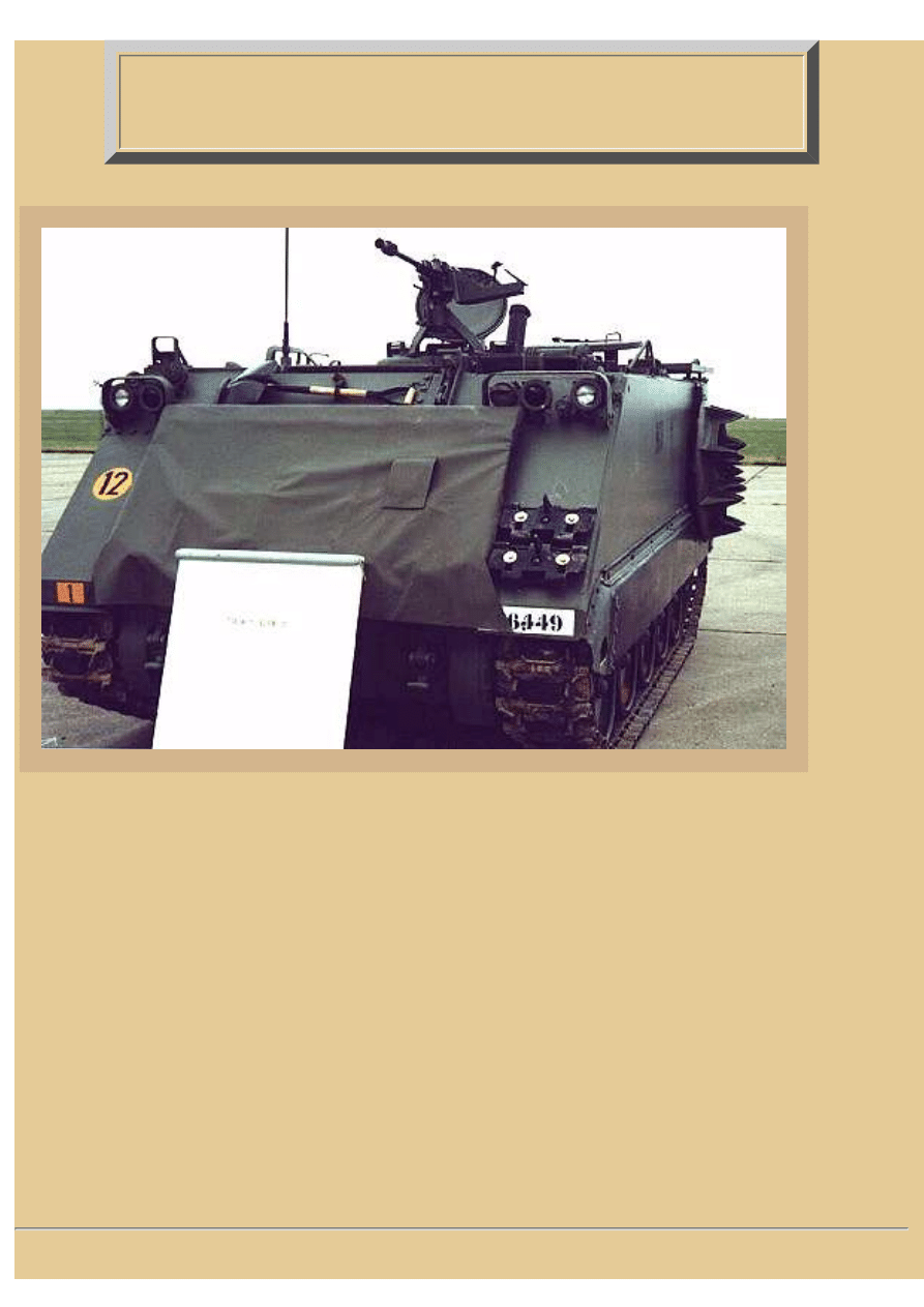
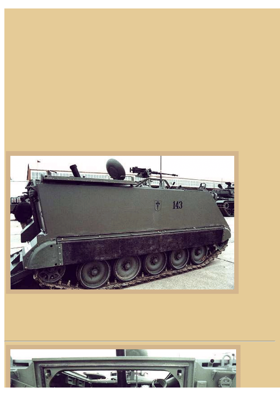
Picture 2:
From outside
the Spanish
120mm
mortar
carrier you
can clearly
see the
characteristic
lines of the
simple
aluminum
box hull of
the FMC
M113
design. Up
on top are
the open
commander
and driver's access hatches, the commander's hatch ring mounting a flexible .50cal Browning HB
Machine Gun. Notice that there are no external fuel tanks on the rear of the hull, one of a number of
indications that this vehicle is based on the M113A1 when the fuel tank was still located inside the cargo
compartment, not on an A2 or later vehicle.
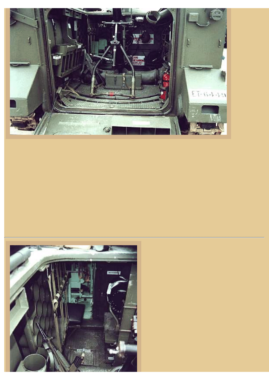
Picture 3:
The first
thing I
noticed
file:///H|/Modellismo/AFV%20Interiors/[armor]%20-%20AF...iors/afvinteriors.hobbyvista.com/m113toa/m113toa1.html (2 di 6)25/05/2007 16.47.17
file:///H|/Modellismo/AFV%20Interiors/[armor]%20-%20AFV%20Interiors/afvinteriors.hobbyvista.com/m113toa/m113toa1.html
when
looking at
this image
of the
interior of
the rear
compartment
is that this
ECIA
120mm
mortar has a
completely
different
base setup
than any I
have seen
inside a
M113
mortar carrier before, certainly different than the US M106A1 (107mm), M125A1 (81mm), and M1064
120mm Mortar Carriers. In all the US M113-based mortar carriers, the mortar tube is mounted on a fully
rotating turntable and can theoretically traverse to fire in any direction. The 120mm mortar tube setup
seen in this Spanish vehicle does not have that ability. It is mounted in such a way that the mortar
traverses through a limited arc, approximately 70 degrees, and only when the weapon is pointed toward
the rear. You can clearly see where the bottom of the forked tube support runs along a track that arcs
gently across the floor. You can also see that the lower end of the mortar tube is attached to ball socket on
a tunnel support (that runs across the floor from sponson to sponson), again different than all the US
carrier platforms I am familiar with. It is clear that the stowage along the both sidewalls is also different
here, the ammo stored vertically and horizontally in different locations and in different bin designs than
on the US vehicles.
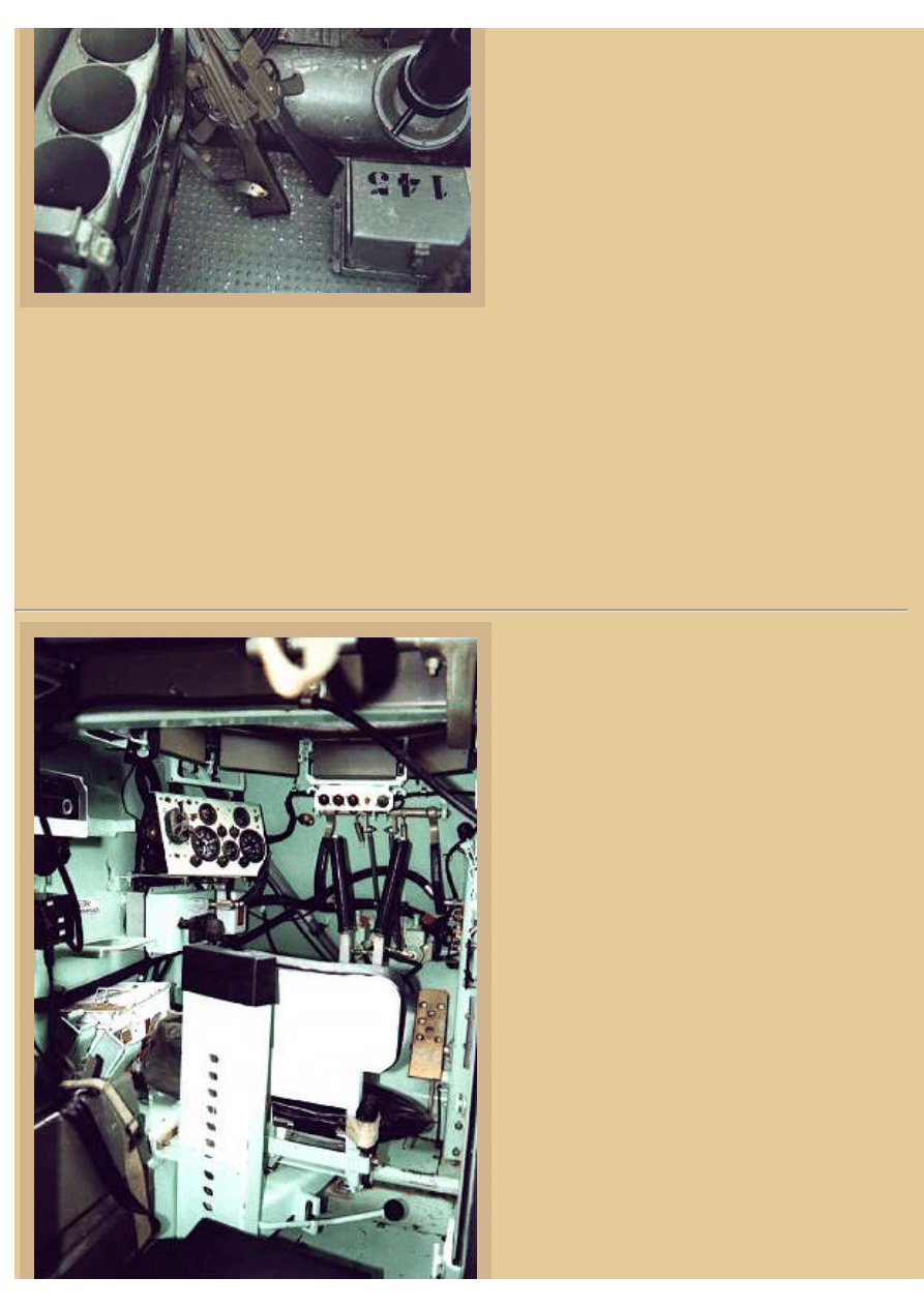
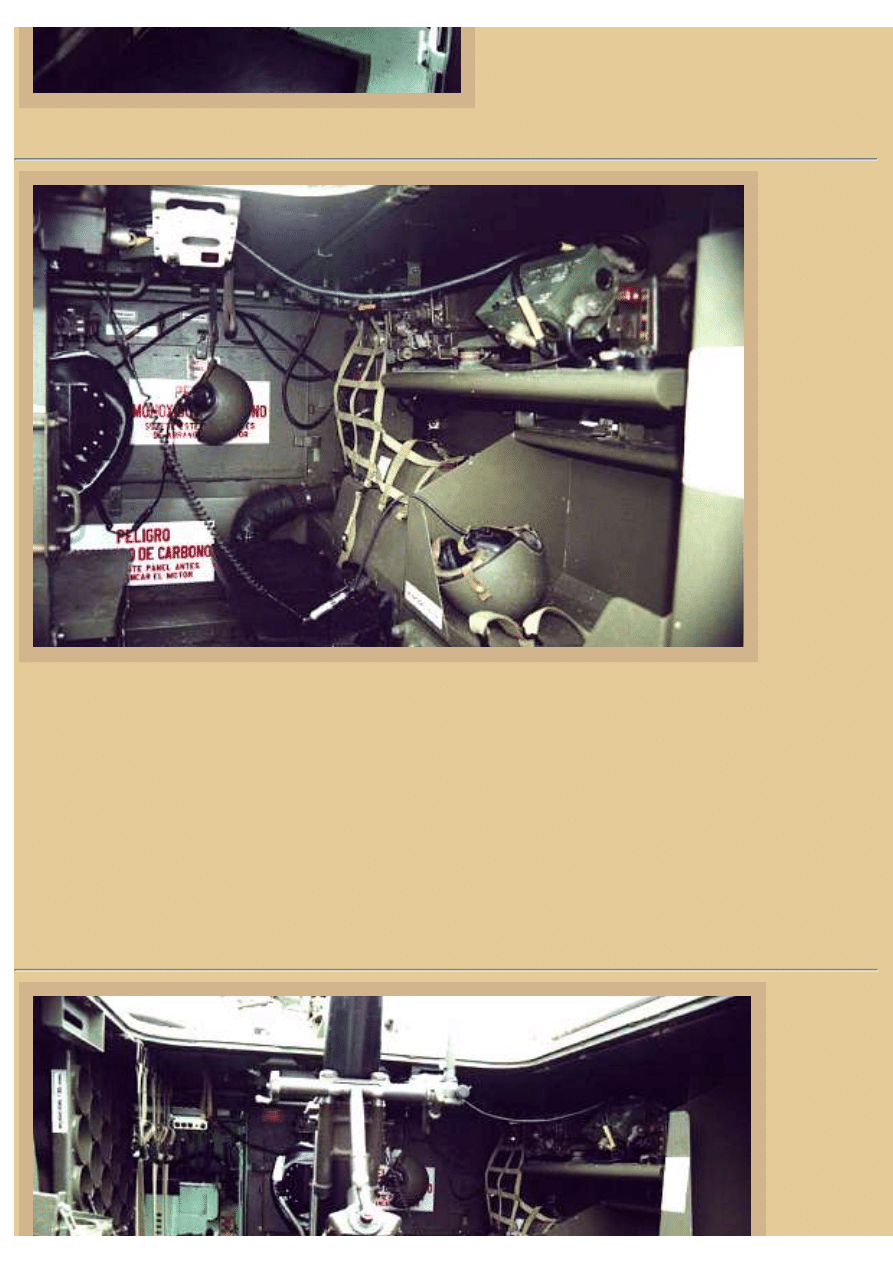
Picture 4:
A closer view of the left side of the hull interior
shows the ammo storage on the side wall of the
Spanish hull next to the 120mm mortar tube (the
tube is also called a "cannon" on occasion). The
tube support tunnel that runs from side to side is
clearer in this image. On the left hull wall are
vertical ammo storage tubes bolted to the floor
next to the fuel cell (that sits up on the sponson).
You can also just barely see a number of
horizontal ammo storage tubes on the left
sponson, forward of the fuel cell. Further
forward are some shelves with webbing straps
and then further forward still are the driver's
controls. The mortar crew apparently carry
assault rifles inside the vehicle, the weapons
appearing to be Spanish CETME Modelo L
file:///H|/Modellismo/AFV%20Interiors/[armor]%20-%20AF...iors/afvinteriors.hobbyvista.com/m113toa/m113toa1.html (3 di 6)25/05/2007 16.47.17
file:///H|/Modellismo/AFV%20Interiors/[armor]%20-%20AFV%20Interiors/afvinteriors.hobbyvista.com/m113toa/m113toa1.html
assault rifles.
At the upper right is the commander's seat and
seat support rising from the floor to the ceiling,
the same setup as seen in most M113 series
vehicles. The seat allows the commander to ride
low in the hull under armor using periscopes to
view the surroundings, or high, with his head out
of his over-head hatch. Down below the mortar
is an equipment box with the vehicle track
number 143.
About those assault rifles.... After WWII, the core of the Mauser team which designed the German
Sturmgewehr 44 went to work for the Spanish CETME (Centro de Estudios Tecnios de Materials
Especiales) and developed a new assault rifle based on its original layout. The resulting weapon was made
of low-grade steel and was built with the emphasis on cheapness and reliability rather than good looks.
The Spanish army adopted the resulting CETME B, or 58, as its standard rifle in 1958, the weapon
chambered for a unique light 7.62mm round. In 1964, Spain decided to adopt the more powerful 7.62mm
NATO cartridge and CETME modified their rifle design to make the Modelo 58 C. The most recent
version of the rifle was first produced in 1984 to use the NATO 5.56mm round, and that CETME Model
L is what we see here (thanks Javier Hueso and Gorka L. Martinez Mezo).
Picture 5:
This shot of the driver's compartment in the
Spanish vehicle is pretty much stock M113A1,
with the steering tillers in front of his seat, the
periscopes over his head around his roof hatch,
and his primary instrument panel to the left of
the driver, angled slightly for improved viewing.
The shelves to our immediate left are usually
reserved for radios, but I can see only an
intercom connect box here, the radios have been
moved over to the other side of the hull, out of
our sight. Again, you might want to compare
this photo with others in the M113 web page in
AFV INTERIORS to see what minor
differences you can find between the vehicles.
file:///H|/Modellismo/AFV%20Interiors/[armor]%20-%20AF...iors/afvinteriors.hobbyvista.com/m113toa/m113toa1.html (4 di 6)25/05/2007 16.47.17
file:///H|/Modellismo/AFV%20Interiors/[armor]%20-%20AFV%20Interiors/afvinteriors.hobbyvista.com/m113toa/m113toa1.html
Picture 6:
Here is the
view of the
right side of
the Spanish
hull interior.
The upper
shelves are
filled with
radio gear
and the lower
ones are
empty right
now, with the
exception of
a "bone
dome"
helmet.
Further
forward is
another
armored vehicle crew helmet, hanging from the rear engine compartment access hatch. Notice that the
typical warning signs about carbon monoxide poisoning are in the same place as in the US vehicles, but
now they are in Spanish. Down to the lower right of the access hatch is the large black duct for the crew
heater, again the same as in US vehicles. The white dome light on the ceiling is the same, and even the
radio gear looks familiar to me, although I am no expert on modern vehicle radios. One of our readers,
Mr. Alastair Bowie, wrote to reminded me that the set is either an AN/VRC 160 (with AN/PRC 77) or
AN/VRC 125 (with AN/PRC 25). Both sets are externally just about identical, except the ID plate. By the
way, the AN/PRC 77 is being replaced by the PR4G family of radios but still survives in second line
units. All Spanish first line units have converted to the digital PR4G family of vehicular sets (thanks again
Al and Gorka for your help here).
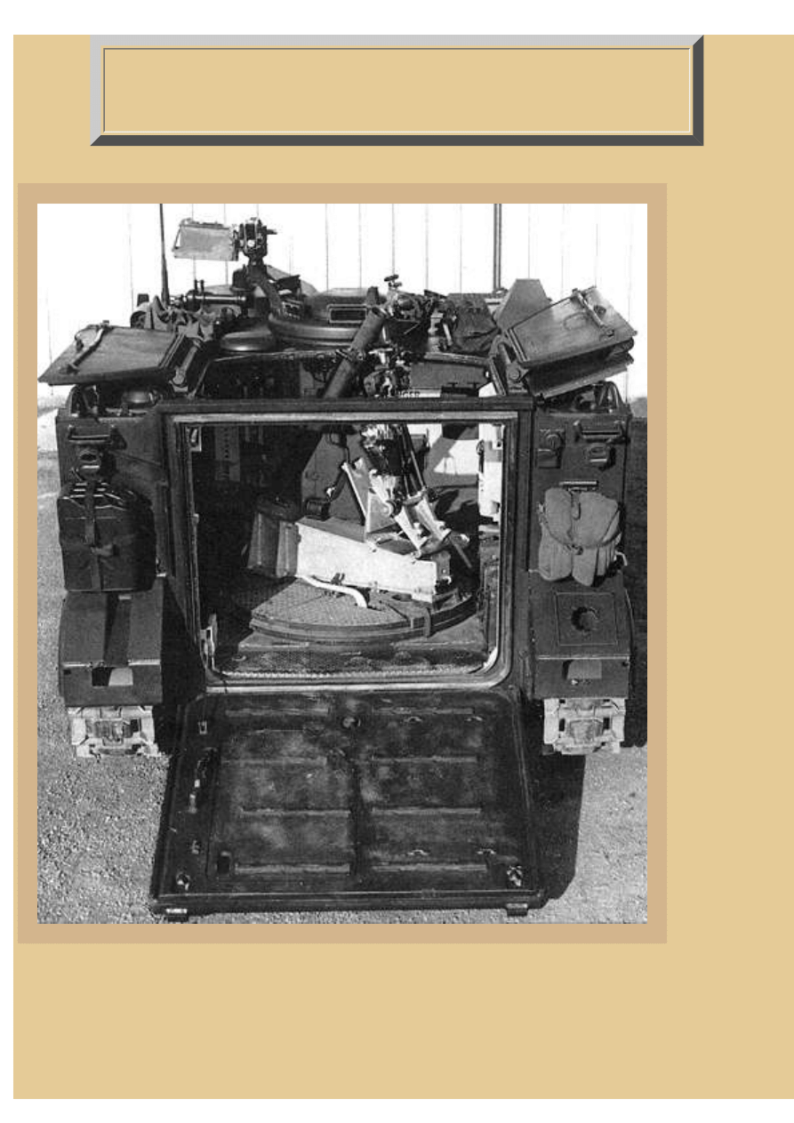
Picture 7:
Stepping
back down
the lowered
rear ramp
we once
again have
an excellent
overall view
file:///H|/Modellismo/AFV%20Interiors/[armor]%20-%20AF...iors/afvinteriors.hobbyvista.com/m113toa/m113toa1.html (5 di 6)25/05/2007 16.47.17

file:///H|/Modellismo/AFV%20Interiors/[armor]%20-%20AFV%20Interiors/afvinteriors.hobbyvista.com/m113toa/m113toa1.html
of the
Spanish
120mm
mortar
carrier
compartment
and mortar.
The forked
support
brace for the
tube can be
adjusted to
elevate or depress the weapon, the mechanism to do this seen directly in front of us. This forked support
brace is also used on a portable base which is normally hung on the side of the hull, so the tube probably
releases from its pivot on the tunnel support so it can be removed from the vehicle and set up
independently. The support tubing is very similar to the design used on the US M1064 120mm Mortar
Carrier, except this one has the support legs bent into angles to fit the track on the floor, and the US
support legs are straight. Again, notice how massive the tunnel support appears in this photo, especially
how the ends are bolted to the side hull sponsons with cast plates and numerous bolts.
The cargo doors are open over-head and provide more than enough clearance for the limited rear traverse
of the big mortar. Having to open up an armored vehicle in order to fire its main weapon like this is one of
the main drawbacks of using the M113 as a mortar carrier. When used like this, the crew is very exposed
when setting up and firing the mortar, for the crew is exposed not only to over-head shell bursts, but also
to any NBC contamination. Some countries (those with deep enough pockets) are gradually converting
their open mechanized mortar carriers to enclosed and turreted types for this reason. One example of the
newer enclosed type that comes to mind is United Defense's 120mm Armored Mortar System (AMS)
120mm mortar turret, which can be mounted on a number of different chassis. But there are others now
available and currently in trials.
That concludes Part 1. In Part 2 we will take a look inside the three American vehicles based on the M113
that have been used over the past few years, and compare them to this Spanish version.
TO M113 MORTAR CARRIERS PART 2
BACK TO AFV INTERIORS HOME PAGE
(c) 2002, 2003 AFV INTERIORS Web Magazine
file:///H|/Modellismo/AFV%20Interiors/[armor]%20-%20AF...iors/afvinteriors.hobbyvista.com/m113toa/m113toa1.html (6 di 6)25/05/2007 16.47.17
file:///H|/Modellismo/AFV%20Interiors/[armor]%20-%20AFV%20Interiors/afvinteriors.hobbyvista.com/m113toa/m113toa2.html
M113 Mortar Carriers, Part 2, Revised
April 26, 2002
Picture 1:
This is the
second part
of a two-part
series on
M113-based
mortar
carriers. In
Part 1 we
looked inside
a modern
Spanish
carrier with a
120mm
mortar, and
now, for
comparison,
we will
briefly
explore the
three M113-
based carriers
that have
been used by
the US over
the past few
years.
This is a US
Army photo
of the view
inside a US
M125A2
with its
81mm M29
Mortar installed. Notice the fully rotating turntable on the floor with the mortar elevated on a
platform that is centered on the turntable. The elevated platform was necessary because the mortar
tube was short and the platform ensured the blast from firing the mortar was directed completely
outside the vehicle. Notice that the roof hatches over the mortar are now circular instead of
rectangular as seen on the various versions of the basic M113.
file:///H|/Modellismo/AFV%20Interiors/[armor]%20-%20AF...iors/afvinteriors.hobbyvista.com/m113toa/m113toa2.html (1 di 9)25/05/2007 16.47.18
file:///H|/Modellismo/AFV%20Interiors/[armor]%20-%20AFV%20Interiors/afvinteriors.hobbyvista.com/m113toa/m113toa2.html
As I mentioned, the mortar used in the M125 series of vehicles was the well-known and trusted
81mm M29, with roots going all the way back to the French and WWI, but best known when used by
the US Army as the 81mm Mortar M1. As the M1, the 81mm Mortar tube weighed only 44lbs and
was less than four feet long. While muzzle velocity was only 700ft/sec, it could lob rounds over a
mile and a half, at the rate of 18 to 30 per minute, depending on the crew and local conditions. With a
few minor modifications, including beefing up the tube from low to medium pressure, the M1 Mortar
was renamed the M29 Mortar in the late 1950's. As carried inside the M125 Mortar Carrier, the M29
Mortar could be dismounted and deployed away from the vehicle using a portable base plate that you
can see here stowed on the roof to the left of the commander's cupola.
There were stowage bins for 114 mortar bombs and fuzes carried inside and, as you can see, a .50cal
Browning M2 HB was also mounted on the commander's cupola ring. Over the past twenty years or
so the US Army has been in the process of converted these vehicles to the 120mm Mortar Carrier
M1064, or other similar configurations, and to the best of my knowledge this has now been
completed. There are very few, if any, M125 81mm Mortar Carriers in the US inventory now, but at
one time it was a dedicated part of many armor and infantry unit assets.
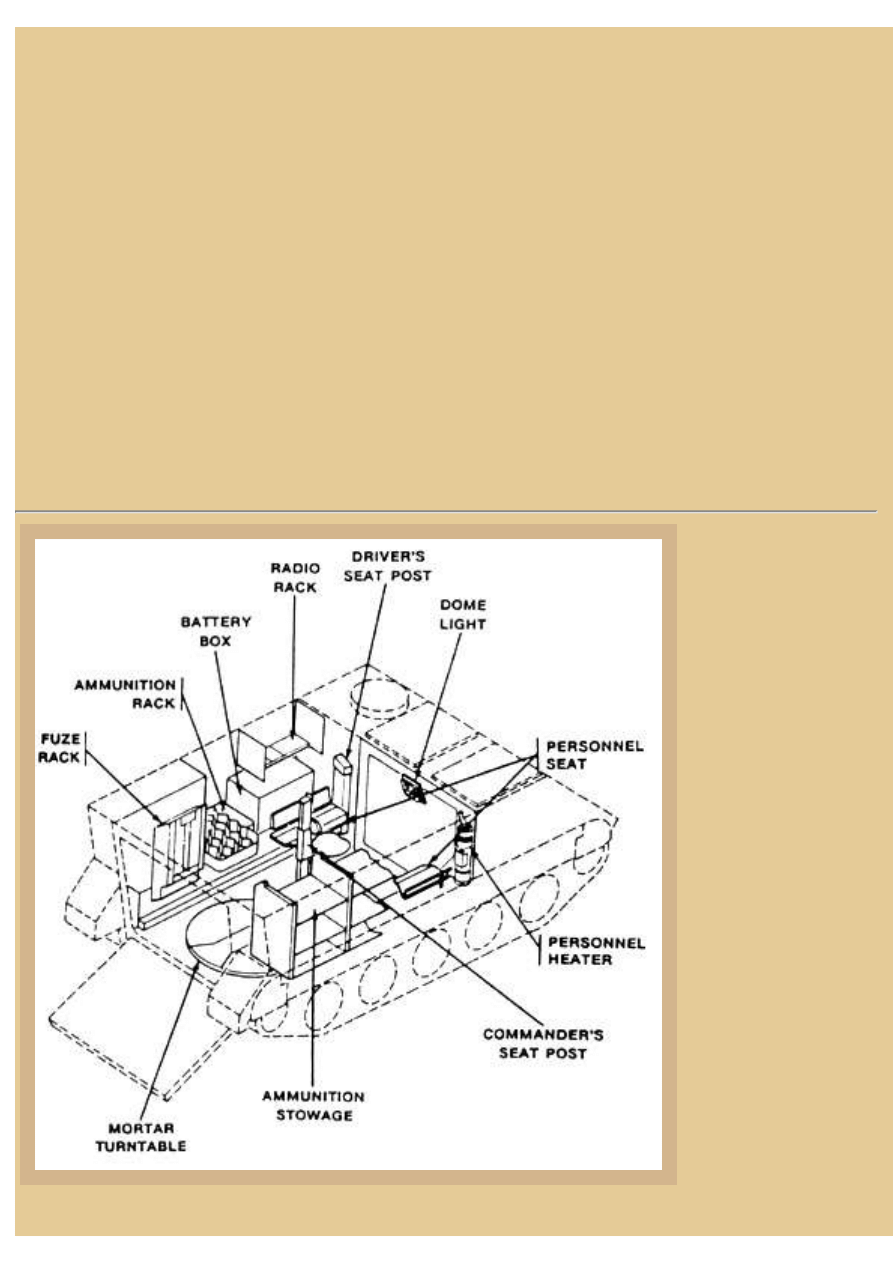
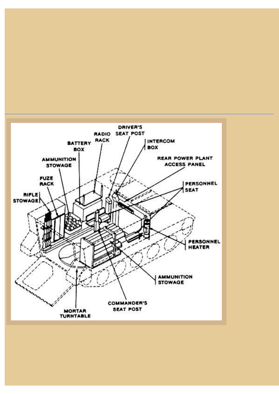
Picture 2:
This is the interior
stowage drawing for
the M125A2 carrying
the 81mm M29
Mortar. Beginning at
the left rear, you can
see a fuze rack located
next to the fuel cell (in
its typical position up
above the left track).
Further forward on the
left track sponson is a
vertical stowage rack
for ready round
mortar bombs, and
further forward still is
the large battery box
with a radio rack shelf
above. Mounted next
to the battery box and
radios is a crew seat,
and a similar seat is
seen across the
vehicle on the
opposite side.
file:///H|/Modellismo/AFV%20Interiors/[armor]%20-%20AF...iors/afvinteriors.hobbyvista.com/m113toa/m113toa2.html (2 di 9)25/05/2007 16.47.18
file:///H|/Modellismo/AFV%20Interiors/[armor]%20-%20AFV%20Interiors/afvinteriors.hobbyvista.com/m113toa/m113toa2.html
The crew heater occupies this forward right corner of the track while further back from the second
crew seat along this side are two more bins for mortar bombs, this time the bombs stowed
horizontally. Typically, at the time the M125A2 was in use, mortar bombs were stowed in their own
protective tubes, and the black tubes would be seen lying on these shelves when the vehicle was fully
stowed and ready for action.
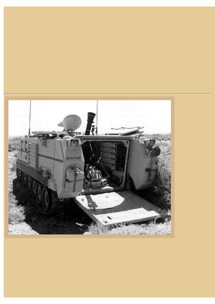
Picture 3:
Also
recently
phased out
of US
Army
service is
the M30
107mm
(4.2inch)
mortar.
Most of
these
weapons
were
removed
from
active and
reserve
units
during the
1980s, in
favor of
the NATO
standard
M120
120mm
Mortar.
However,
the old
M30
107mm
mortar can
still be
found in
some
NATO
countries. This is the M113-based carrier for the mortar, known as the M106 series of Mortar
Carriers. Like the M125 Carrier with the 81mm mortar, the M106 Carrier had to stop first in order to
file:///H|/Modellismo/AFV%20Interiors/[armor]%20-%20AF...iors/afvinteriors.hobbyvista.com/m113toa/m113toa2.html (3 di 9)25/05/2007 16.47.18
file:///H|/Modellismo/AFV%20Interiors/[armor]%20-%20AFV%20Interiors/afvinteriors.hobbyvista.com/m113toa/m113toa2.html
setup before the weapon could be fired from inside the carrier. Like most other mortars that were
mounted inside US carriers, the 107mm mortar could be dismounted from the M125 carrier and used
away from the vehicle. In this case, the large base plate is stowed hanging on the left side of the
vehicle hull; only part of it is visible at the far left.
Known to many who used it as the 4.2in (more about this later), the M30 107mm mortar was
designed a bit differently from others in the US inventory, in that it had a rifled tube which stabilized
the bomb by spinning it rapidly while in flight. Again, notice that the weapon is mounted on a fully
rotating turntable, similar in design to the one used in the M125, although the tube support is quite
different in appearance, consisting of a single tube while the support for the 81mm M29 mortar is
forked.
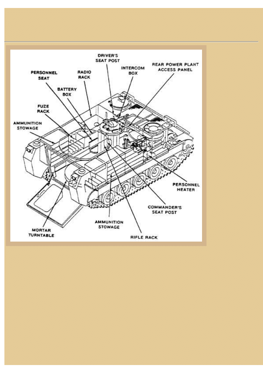
Picture 4:
And here we
have the interior
storage sketch
from the manual
for the M106A2
Mortar Carrier
with the 4.2in
(107mm) inside.
The original
M106A1 was
first produced in
September of
1964 and for
many years was
the standard
Mortar Carrier
for the US
Army. The
interior setup is
similar in some
respects to what
we saw in the
M125A2. Again,
beginning at the
left-rear, there is
a fuze rack next
to the fuel cell, but now there is also a rifle rack next to the fuze rack. Further forward from the fuel
cell on the sponson is the same vertical ready round storage rack we saw previously, and further yet
along the sponson is the battery box with radio rack above and crew seat along side.
Another crew seat is across the isle next to the crew heater, and then there are two bins with shelves
again for mortar bomb storage, very similar in most respects to the interior arrangement of the
file:///H|/Modellismo/AFV%20Interiors/[armor]%20-%20AF...iors/afvinteriors.hobbyvista.com/m113toa/m113toa2.html (4 di 9)25/05/2007 16.47.18
file:///H|/Modellismo/AFV%20Interiors/[armor]%20-%20AFV%20Interiors/afvinteriors.hobbyvista.com/m113toa/m113toa2.html
M125A2. Both vehicles also have the commander's seat support post and seat in the typical location
toward the front of the fighting compartment so he is located directly under his cupola.
The US M30 4.2in Mortar (also known as the "four-deuce") originated as the M2 Chemical Mortar
and was first designed to fire white phosphorus, smoke, Lewisite (an organic arsenic gas compound),
choking gas, mustard gas, and two types of tear gas back in the days of the Great War. In 1951 it was
modified slightly and renamed the M30 4.2in Mortar, officially only later becoming the M30 107mm
Mortar in order to conform with standard NATO criteria. As the M30 107mm Mortar, the weapon
was said to have elevation limits of 45 to 85 degrees with a traverse of 16 degrees without having to
move the base. The most common bombs in use at this time were high explosive, white phosphorus,
chemical, and illuminating, with a range of around 3.5 miles. Rate of sustained fire was said to be
around 20 to 25 rounds per minute, with a muzzle velocity of around 960 ft/sec.
Picture 5:
And finally, this
is the current US
M1064A3
Mortar Carrier
with its 120mm
M121 mortar
(also known as
the Battalion
Mortar System--
BMS), the
mortar looking
suspiciously like
an Israeli
120mm Soltam
mortar. Not only
does this vehicle
have the two
rear external
fuel tanks, but it
is also fitted
with the RISE
powerpack
(275hp Detroit
Diesel 6V53T turbocharged diesel engine driving through an Allison X200-4 cross-drive
transmission).
Also, you may have noticed that unlike the Spanish vehicle in Part 1, the US 120mm Mortar Carrier
still uses a fully rotating turntable. The M1064A3 vehicle has the same general silhouette as the
M113A3 personnel carrier, but there are structural differences, including a welded-in cross beam,
additional floor support structures to withstand mortar reaction forces, and an enlarged three-piece
over-head firing hatch. And although the 120mm weapon seems to have a 90 degree traverse
file:///H|/Modellismo/AFV%20Interiors/[armor]%20-%20AF...iors/afvinteriors.hobbyvista.com/m113toa/m113toa2.html (5 di 9)25/05/2007 16.47.18
file:///H|/Modellismo/AFV%20Interiors/[armor]%20-%20AFV%20Interiors/afvinteriors.hobbyvista.com/m113toa/m113toa2.html
potential on the turntable, the vehicle still has to be positioned so the mortar is fired to the rear.
Typically, all the M1064s have a four-man crew and a total of 69 mortar bombs stowed onboard.
Picture 6:
The stowage
diagram from the
manual shows how
this interior is very
different than the
two earlier
designed M113-
based vehicles we
have seen. Since
the fuel cells are
now outside, there
is more room for
ammo storage
inside. A large
shelved bin at the
left-rear corner of
the compartment
takes the place of
the fuel cell, and
further forward is a
revised rack for the
fuzes. The battery
box is in the same
location in the A3,
and the typical
location for the
radio shelf is still above the battery box. Crew seats are again next to the battery box and also across
the isle, but now there is a rifle rack mounted directly behind the commander's seat, partially
obscuring his position when you look into the vehicle from the open ramp. On the right side of the
hull are additional horizontal storage racks for additional bombs while a second fuze rack takes the
remaining space at the right rear.
Lockheed Martin Ordnance Systems was selected in 1988 as the primary contractor for R&D and
initial production of the US 120mm mortar and ammunition. Lockheed Martin teamed with Soltam
Limited of Israel (thus the similarity in appearance of the two 120mm systems) for the design.
Subsequently, the U.S. Army awarded Watervliet Arsenal the primary contract for weapon
production under the Arsenal Act competition, along with Martin Marietta. Approximately 1,190 of
the earlier M1064 carriers were to be converted to the M121 BMS systems (M1064A3) and the same
number of M121 Mortars were to be produced, for a total cost of around 108 million dollars.
Conversion of the earlier vehicles ran to June of 1998, and production of the M121 Mortars ended in
October of 1996.
file:///H|/Modellismo/AFV%20Interiors/[armor]%20-%20AF...iors/afvinteriors.hobbyvista.com/m113toa/m113toa2.html (6 di 9)25/05/2007 16.47.18
file:///H|/Modellismo/AFV%20Interiors/[armor]%20-%20AFV%20Interiors/afvinteriors.hobbyvista.com/m113toa/m113toa2.html
Current enhancements to the system include an improved sight unit, improved smoke round,
conventional and infrared illumination rounds, a full-range training round, and the M30 mortar
ballistic computer. Proposed long-term enhancements include extended range precision guided
munitions and a digital fire control system; a few of the guided munitions are currently under test and
could provide some very interesting options for the mortar system.
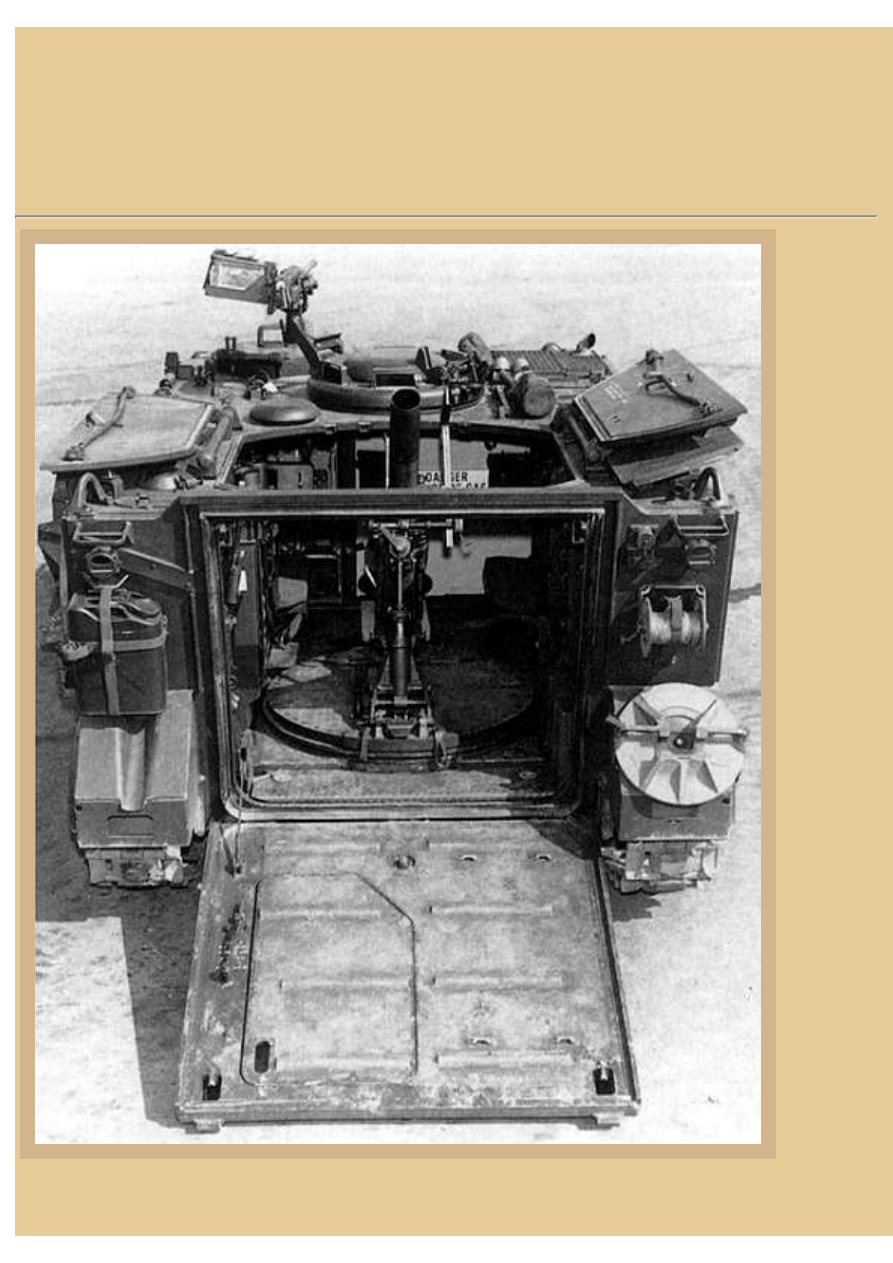
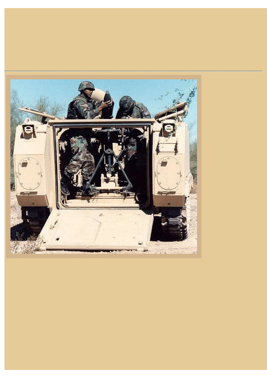
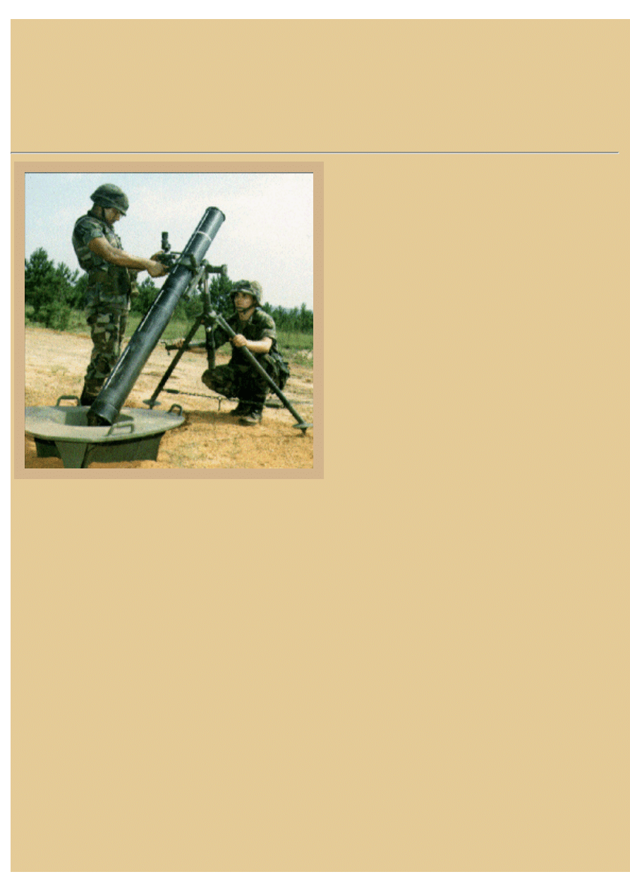
Picture 7:
Another US Army
photo of a M1064A3
120mm Mortar Carrier
compares the relative
size of the vehicle and
a typical 120mm
round to the size of the
crew members. It is
hard to believe that
any crew would want
to be inside this thing
when the huge mortar
is fired, the blast
effects on surrounding
troops are world
famous. The mortar,
especially when fired
inside the carrier,
produces a blast
overpressure (impulse
noise level) in excess
of allowable limits.
Crew members that
are subjected to this
blast overpressure must wear properly fitted E-A-R brand disposable earplugs, and soldiers in the
immediate vicinity of the mortar firing (within 200 meters) must have properly fitted hearing
protection. When firing in the carrier-mounted mode, a Blast Attenuation Device (BAD) is attached
to the muzzle of the M298 cannon to reduce the blast effects on the mortar crew. You can see this
device in this photo as well as others, the device is the funnel-shaped addition at the end of the mortar
tube.
According to the US Army's published Basis Of Issue Plan (BOIP), provisions are made inside the
M1064A3 for three M16A2 rifles, a sight extension, and an extractor rod directly to the rear of the
commander's platform seat. Other modifications beyond the A2 version include improved driver
controls, a shock-mounted driver's seat, collapsible driver's footrest, and mounting provisions for a
bolt-on armor kit. The vehicle complements other battalion organic weapon systems by transporting
the mortar in order to provide a high rate of high angle support to engage defilade targets and fill in
file:///H|/Modellismo/AFV%20Interiors/[armor]%20-%20AF...iors/afvinteriors.hobbyvista.com/m113toa/m113toa2.html (7 di 9)25/05/2007 16.47.18
file:///H|/Modellismo/AFV%20Interiors/[armor]%20-%20AFV%20Interiors/afvinteriors.hobbyvista.com/m113toa/m113toa2.html
areas of dead space for direct fire weapons. As I mentioned, the M1064A3 Carrier is currently
replacing the earlier versions on a one to one basis, primarily in Armored and Mechanized Infantry
Battalions (six or four each), Armored Cavalry Squadrons (three per troop) and in Motorized Infantry
Battalions (six each). Typically, the crew consists of a squad leader, gunner, assistant gunner, and
ammo bearer/operator/driver.
Picture 8:
Our final image illustrates the US 120mm
mortar, designated as the M121 when carrier
borne, and M120 when towed. Range with
current munitions is approximately 7,240m and
rate of fire, depending on crew, is stated to be
16 rounds/min for the first minute and then four
rounds/min sustained. Weight of the mortar,
support and base is 319lbs and ammunition now
consists of high explosive, smoke, illumination
(visible light and infrared), and full-range
practice. A Mortar Fire Control System (MFCS)
is currently in development for coordinating fire
missions and should be available in the near
future. When towed behind a M998 HMMWV,
the mortar is transported on its own M1100
trailer and a five man crew is required.
Elevation is from 710 to 1510 mils (40 to 85
degrees) while deflection is approximately 272 mils total, right to left. Each turn of the traversing
handwheel equals approximately 5 mils.
The major components consist of the M298 Cannon, which is a smooth bore type with a crew
removable base cap. When fired from a M1064 Mortar Carrier, a Blast Attenuator Assembly is
mounted on the muzzle end as we saw earlier. Weight of the tube alone is 110lbs (50 kg). The mortar
mount is either the M190 or M191 Mortar Mount, allowing cross-leveling, traversing, and elevating
adjustments. The M190 has straight legs (as you see here) and the M191 has removable leg
extensions to allow mounting in the M1064 Mortar Carrier. The mortar mount is equipped with a
buffer mechanism and traversing extension. Weight of the M191 is 78lbs (35.5 kg). The sight being
adjusted here is a M67 Sight Unit, which includes a mount assembly and a 4X elbow telescope with
radioactive tritium used to illuminate scales, indices, level vials, and reticle. Weight of the sight is
2.25lbs (1.02 kg). 120mm smoothbore mortars are also used by France, Germany, Denmark, and
other allied armies. The Russian-developed counterpart is the M43 120mm mortar, which has a range
of 5,700m, weighs roughly 600lbs, and has a six-man crew. All of them are roughly equivalent in
firepower, although western designs have advanced ammunition research ongoing.
And that concludes our brief exploration of a special Spanish Army 120mm Mortar Carrier and the
various modern US M113-based mortar carrier vehicles used over the past 20 years. My thanks again
go to Cesar de los Bueis from Spain for the use of his interior photos of the Spanish Army vehicle.
Thanks also to Javier Hueso, Alastair Bowie, and Gorka L. Martinez Mezo for their comments, which
file:///H|/Modellismo/AFV%20Interiors/[armor]%20-%20AF...iors/afvinteriors.hobbyvista.com/m113toa/m113toa2.html (8 di 9)25/05/2007 16.47.18

file:///H|/Modellismo/AFV%20Interiors/[armor]%20-%20AFV%20Interiors/afvinteriors.hobbyvista.com/m113toa/m113toa2.html
greatly improved the pages. The other illustrations used in these two web pages are mainly FMC or
US Army photographs and diagrams, coming either from their publicity packets or directly from the
operator's manuals in my own library.
TO M113 MORTAR CARRIERS PART 1
BACK TO AFV INTERIORS HOME PAGE
(c) 2002, 2003 AFV INTERIORS Web Magazine
file:///H|/Modellismo/AFV%20Interiors/[armor]%20-%20AF...iors/afvinteriors.hobbyvista.com/m113toa/m113toa2.html (9 di 9)25/05/2007 16.47.18
Document Outline
Wyszukiwarka
Podobne podstrony:
AFV Interiors Water Buffalo
Afv Interiors Isu 152
AFV Interiors CV 33 35
AFV Interiors German AFV Radio Equipment In WWII
AFV Interiors M1A2 Abrams
AFV Interiors British Medium Tank Mk I & Mk II
AFV Interiors Czech Light Tank, LT vz 38, Pz Kpfw 38(t)
AFV Interiors Leopard 2
Afv Interiors Daimler Scout Car
AFV Interiors Otter
AFV Interiors B1 bis
Afv Interiors Mk V
AFV Interiors Marder III
AFV Interiors Fahrpanzer
AFV Interiors Semovente Da 75 18
AFV Interiors LVT
AFV Interiors IS 2
AFV Interiors Flakpanzer 38t
Afv Interiors Medium Tank Mark A whippet
więcej podobnych podstron