file:///H|/Modellismo/AFV%20Interiors/[armor]%20-%20AFV%20Interiors/afvinteriors.hobbyvista.com/leop2/leop2a.html
Leopard 2 Main Battle Tank, Part 1
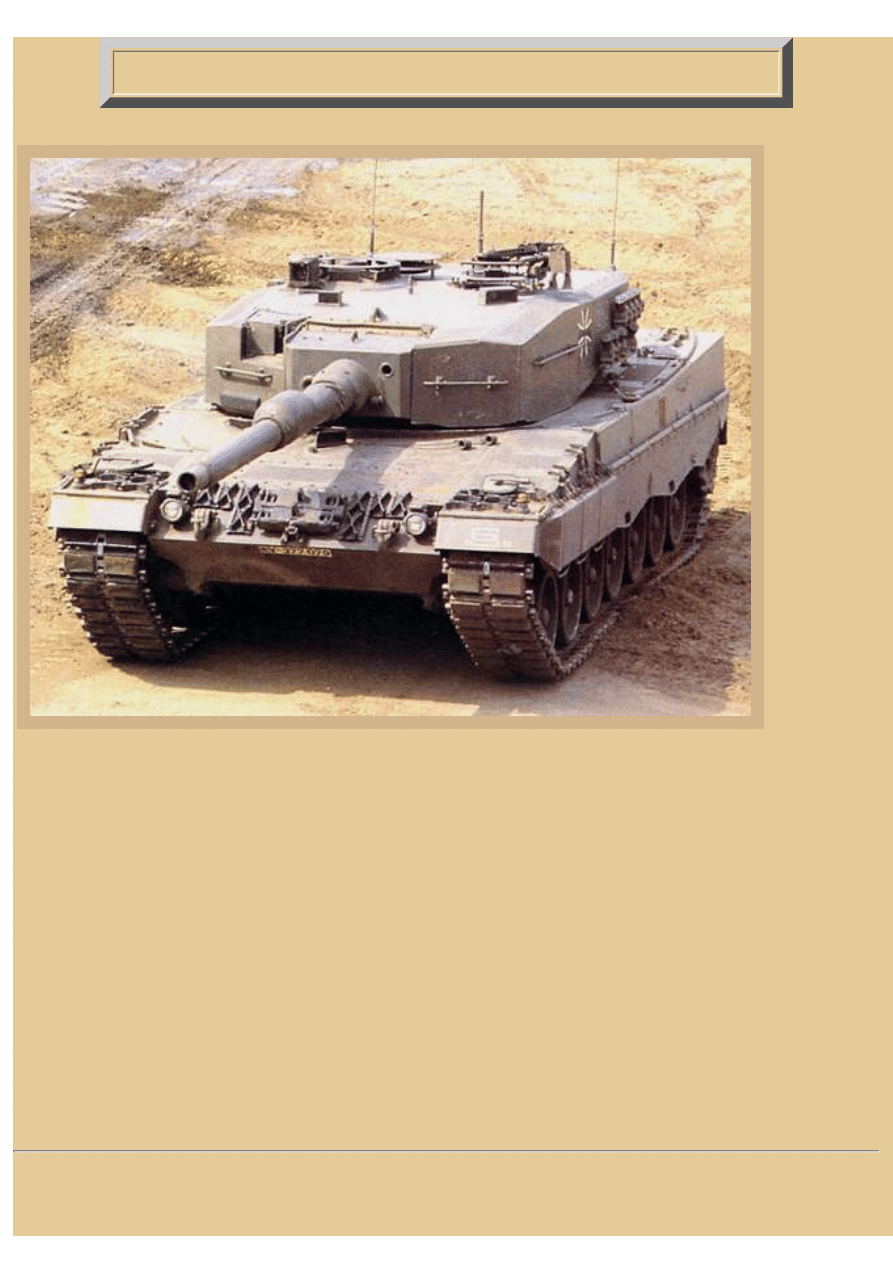
Picture 1:
As Leopard 1
was arriving
for
Bundeswehr
service in
1965, Porsche
engineers
were already
planing its
replacement
on their
drawing
boards. This
new tank was
envisioned
having greater
and more
accurate
firepower
with a bigger
main gun and
improved fire
control. At
about this
same time,
West
Germany and the USA combined their talents and efforts in the hopes of designing and producing a common NATO
MBT (the MBT70 program).
But the MBT70 program did not pan out for either side, and the West German government then decided to return to
their original Leopard 2 design. It was re-evaluated in the light of their extensive MBT70 experience, and with the
hopes of still attracting the Americans with their new tank, some changes were made and the first prototypes tested.
By the time the first batch of new tanks was ready for production at Krupp MaK and Krauss Maffei AG in the late
1970s, the Leopard 2 was armed with the brand new and potent Rheinmetall BK 120mm smoothbore gun, the first to
be mounted on any NATO tank. The Americans, on the other hand, had seen such problems, both military and
political, with the MBT70 program, they decided it would be best for them to start all over with a new more austere
design, the XM1, and part ways with Germany. In the end, both countries did agree on some basic design
similarities, but their designs matured in a number of different ways.
Over the intervening years, the Leopard 2 has been improved through Upgrade Level I and Level II programs, and
the current version, A6, has been clad in a new "third generation composite armour" shell. Most of our effort in this
web page will be centered on examining the original Level I vehicle with its block-shaped turret, but we do have
some basic interior information on the more recent versions that have been fielded.
file:///H|/Modellismo/AFV%20Interiors/[armor]%20-%20AFV...Interiors/afvinteriors.hobbyvista.com/leop2/leop2a.html (1 di 7)07/02/2007 22.17.17
file:///H|/Modellismo/AFV%20Interiors/[armor]%20-%20AFV%20Interiors/afvinteriors.hobbyvista.com/leop2/leop2a.html
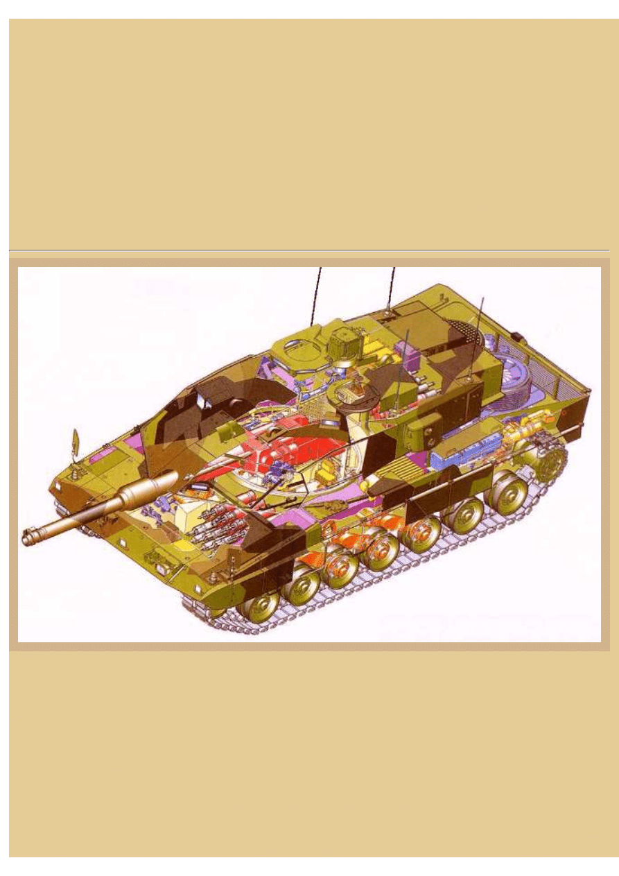
Picture 2:
The AFV's general layout is typical of vehicles of the time with three main compartments. The driver is seated in the
forward hull to the right, and there is a three-man turret crew that consists of a gunner at the front right, commander
at the rear right, and a loader on the left. The hull and turret are both of welded steel with some additional armor
plating mounted on the front surfaces, probably a combination of Chobham and spaced armor. The designers
originally described the layered armor protection as a combination of steels (with various hardness) and elastic
materials in multi-layered sheets. The turret ammunition is stowed in a protected bin at the turret rear, and much of
the hydraulic gun control system packages are also located there.
The driver is provided with a single piece hatch cover that swings open to the right, along with three observation
periscopes, the center of which can be replaced by a passive night periscope. The remainder of the ammunition
supply is stowed to the left of the driver in a large bin, similar to what we have seen in the Leopard 1 tank.
file:///H|/Modellismo/AFV%20Interiors/[armor]%20-%20AFV...Interiors/afvinteriors.hobbyvista.com/leop2/leop2a.html (2 di 7)07/02/2007 22.17.17
file:///H|/Modellismo/AFV%20Interiors/[armor]%20-%20AFV%20Interiors/afvinteriors.hobbyvista.com/leop2/leop2a.html
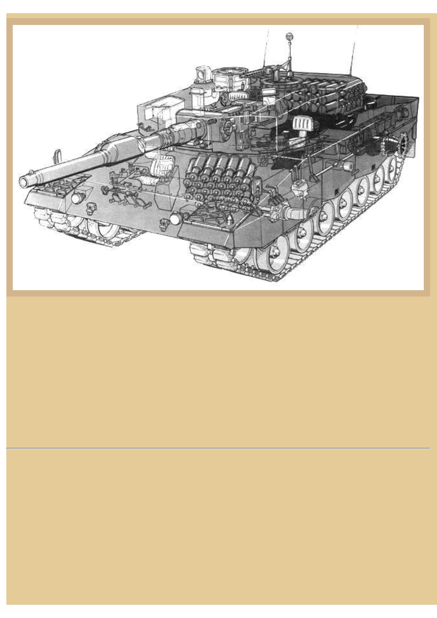
Picture 3:
A simple drawing of the hull identifies many of the main components. The remainder of the front hull not taken by
the driver is filled with the main ammo storage bin (21), and the driver's heater (20). Working our way back along
the left hull side, we find the left hull fuel tank occupying the space above the track sponson and extending all the
way back to a point even with the center of the turret. The same is true on the other side of the hull, with another fuel
tank extending back along the top of the right track sponson. Just behind the left fuel tank on the sponson are the
main components of the NBC collective filtration and protection system, and further back there is a small side
grating for the engine compartment ventilation. Next to the ventilation grate is a line of four batteries (18), and
behind the batteries (and near the rear of the hull) are some of the primary components of the heating system (14).
At the rear of the hull is the air inlet grill (11), the Toroidal cooling system (12) with circular radiator, and the
primary air outlet grill (13) discharging engine cooling air out the back of the compartment. The actual engine
exhausts also exit out the rear plate, but lower down on the hull. Up on the engine deck are two dome-shaped covers
for engine combustion intake air, but only the right cover is seen here as the left side of the deck has been drawn cut
away. Below both the covers are the air filters for the engine, and with the left deck cover removed you can see the
rectangular air filter box below. The right hull side batteries are also drawn in the picture as well as some of the
details of the top of the engine. Inside the turret ring you can see the main hull electrical circuit box on the crew's
side of the firewall, separating two large fuel tanks tucked into the rear corners. A pair of torsion bars crosses the
floor under the turret basket floor, and four 9kg Halon fire extinguisher bottles are clearly seen located along the
right hull wall, just behind the driver's position.
Picture 4:
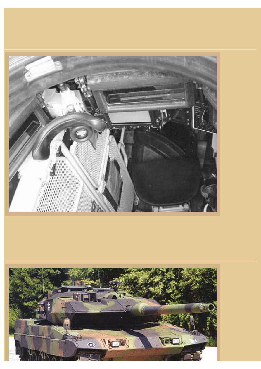
The driver's
area is
surprisingly
file:///H|/Modellismo/AFV%20Interiors/[armor]%20-%20AFV...Interiors/afvinteriors.hobbyvista.com/leop2/leop2a.html (3 di 7)07/02/2007 22.17.17
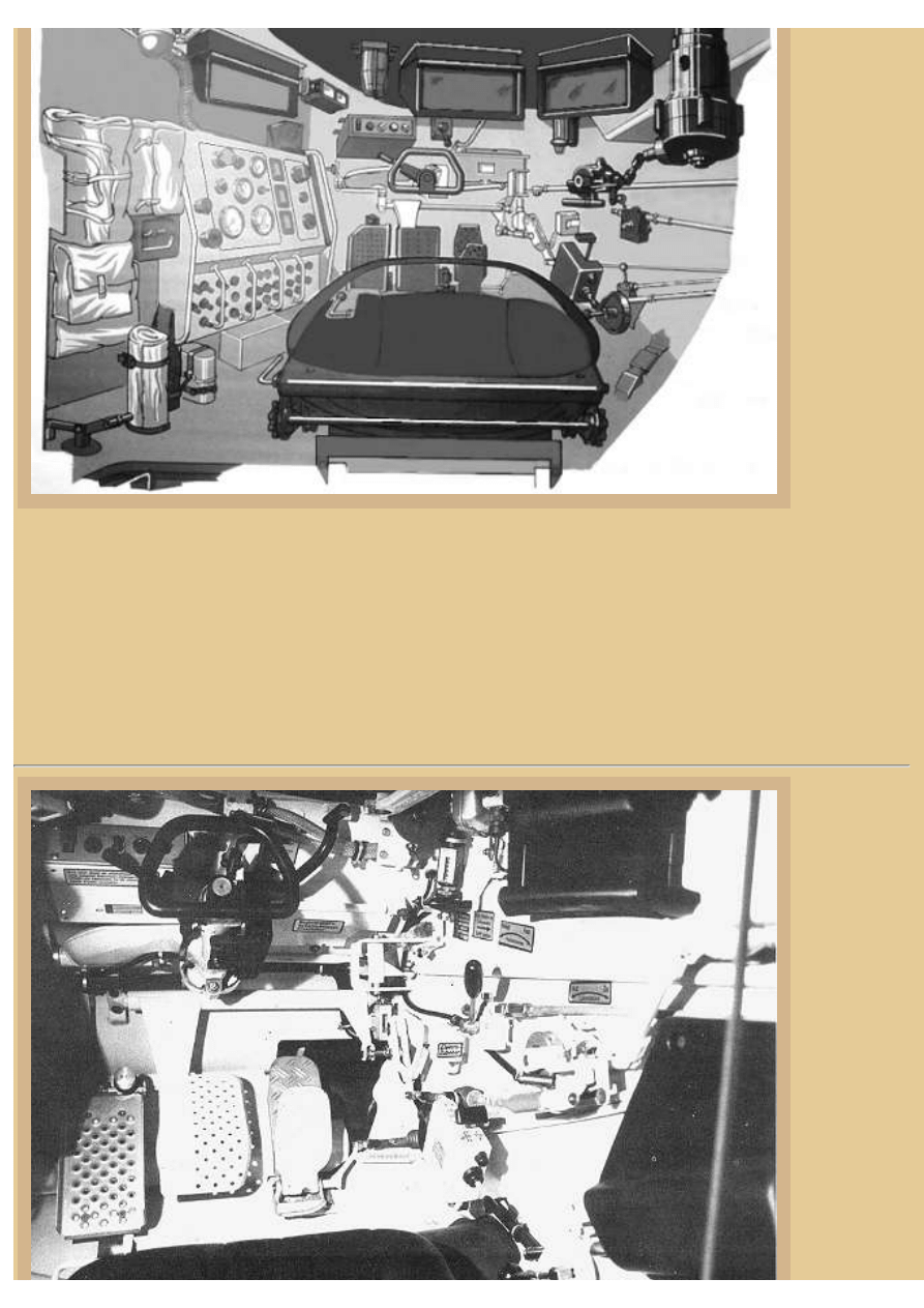
file:///H|/Modellismo/AFV%20Interiors/[armor]%20-%20AFV%20Interiors/afvinteriors.hobbyvista.com/leop2/leop2a.html
roomy and
looks similar
to many other
modern
Western MBT
suites. The
black seat sits
low on the
floor (shown
here with the
backrest
pushed
forward) and
very close to
the right track
sponson. As I
mentioned
before, a large
ammo storage
bin occupies
most of the
rest of the area to the left of the driver, but between the bin and the driver is his large main instrument panel,
containing a tachometer, speedometer, oil and water pressure gages, and electrical control switches.
Overhead are three periscopes; two are mounted in his over-head hatch, and the third is placed to the left and further
forward than the others to improve the view over the top of the left-front hull. A passive night periscope can replace
the center periscope for night observations. The black seat is well padded and the black steering wheel is easily
reached and very comfortable. Down below you can see that the clutch, brake (Teves Hydraulic servo disc), and
accelerator pedals are in their traditional positions. Most of the controls are power assisted in order to ease the
workload of the driver in combat, including the gearshift.
Picture 5:
This Krauss-
Maffei photo
(Krauss-
Maffei AG is
now Krauss-
Maffei
Wegmann
(KMW), of
Munchen,
Germany)
shows a bit
more detail of
the right side
of the driver's
station. The
small
gearshift box
is just a bit
low and to the
right of
file:///H|/Modellismo/AFV%20Interiors/[armor]%20-%20AFV...Interiors/afvinteriors.hobbyvista.com/leop2/leop2a.html (4 di 7)07/02/2007 22.17.17
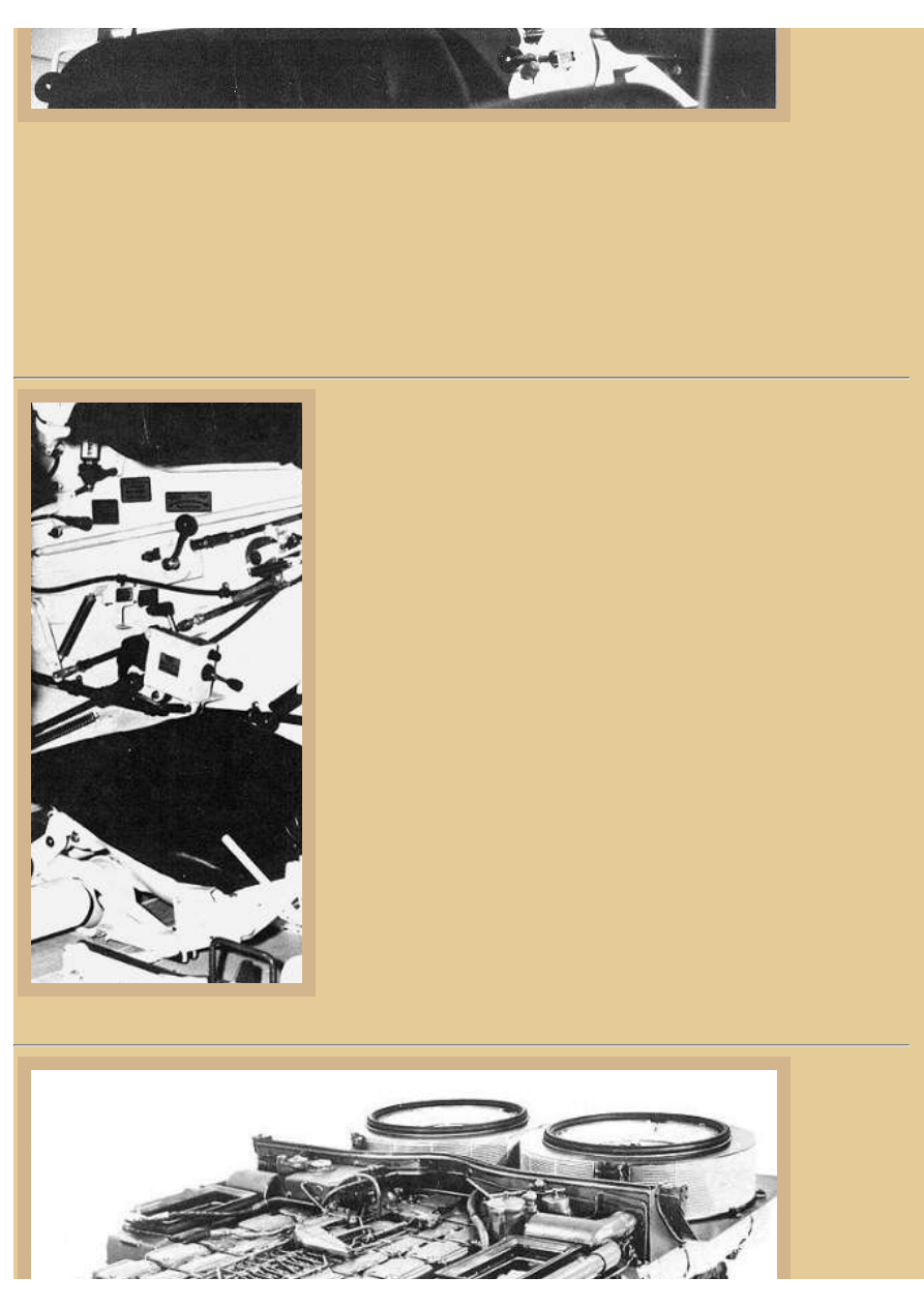
file:///H|/Modellismo/AFV%20Interiors/[armor]%20-%20AFV%20Interiors/afvinteriors.hobbyvista.com/leop2/leop2a.html
center,
between the
seat and the
hull wall, and
it has a black selector knob on the top and gear range selector button on the side. Just above it is a lever with a long
black knob that is used for locking the parking brakes. To the upper right is the right periscope holder and below is a
tangle of mechanical levers that operate the driver's overhead hatch.
In most later Leopard 2 vehicles (although not seen here), there is a television monitor to the left of the driver that is
connected to a camera mounted on the vehicle's rear plate. The camera has a 65-degree horizontal and vertical field
of view towards the rear, allowing the driver to monitor his backing progress. Also not visible here is a floor escape
hatch located immediately behind the driver's seat. The primary interior color throughout the vehicle is gloss white,
with black used for the instrument faces and most of the accessory equipment.
Picture 6:
A slightly different angle of the equipment on the right side of the driver's
area gives some additional detail. His electric gearshift control box with its
two levers is mounted directly on the sponson wall at about knee height, and
above is the parking brake lever, this time with a large ball-shaped handle.
At the top of the picture are the black shapes of the two periscope mounts
with padding around the front edges. Down below you can make out some
of the details of the driver's seat and its connecting hardware that attaches it
to the floor. Note that the seat is mounted above one of the pairs of torsion
bars running from one side of the hull to the other. The seat back has been
reclined all the way flat and can not be seen in the picture. In this position,
the driver may crawl back into the turret if absolutely necessary.
The suspension on the Leopard 2 provides some of the smoothest rides of
any main battle tank. The suspension includes the torsion bars and on each
side there are seven dual rubber-tired road wheels, with the idler at the front,
the drive sprocket at the rear, and four track support rollers. Advanced
friction dampers are provided at the first, second, third, sixth, and seventh
road wheel stations, and combined with the Diehl rubber-bushed tracks with
removable rubber pads, the suspension system provides the smooth and
controlled driving.
So, you may be asking yourself, what kind of a monster engine powers the
Leopard 2, making it one of the best performing MBTs?
Picture 7:
A 12-cylinder
MTU MB873
multi-fuel
engine
provides the
power behind
the Leopard 2,
file:///H|/Modellismo/AFV%20Interiors/[armor]%20-%20AFV...Interiors/afvinteriors.hobbyvista.com/leop2/leop2a.html (5 di 7)07/02/2007 22.17.17
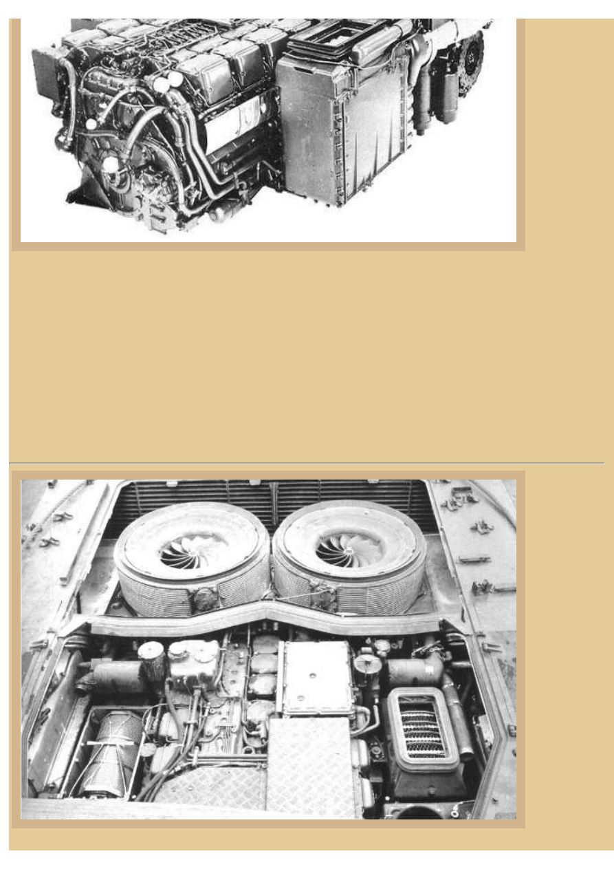
file:///H|/Modellismo/AFV%20Interiors/[armor]%20-%20AFV%20Interiors/afvinteriors.hobbyvista.com/leop2/leop2a.html
with diesel
being the
normal fuel of
choice. The
original
engine design
harkens back
to one
designed for
the aborted
US/German
MBT 70
program, and
it has been
compacted
into a quick-change powerpack that can be removed in about 15 minutes out in the field with the help of a crane. The
MTU MB873 is rated at 1,500hp and provides a power to weight ratio of 27hp/ton, better than most main battle
tanks in operation today. Some of the additional horsepower comes from two exhaust gas turbochargers, located on
the sides between the two air filter boxes and the gearbox at the rear.
The two large circular cooling radiators/fans dominate the rear of the pack, located directly over the gearbox (recall
that there was only one fan over the gearbox on the Leopard 1). These fans draw air into the engine compartment,
cooling the transmission and steering boxes, pulling fresh air through the radiators as it enters. The cooling air is
exhausted out the rear louvers on the back plate, directly above the engine exhaust exits. Total fuel capacity is
around 1,300 liters, allowing a radius of action of around 400km on roads and 220km cross-country. The
transmission at the rear includes a Renk HSWL-354/5 unit with steering unit combined in the same case. To control
the Leopard 2 tank, the driver uses a four-speed planetary gearbox with a bypass clutch and two reverse gears.
Picture 8:
Another
picture of the
engine shows
its appearance
while still
installed in
the Leopard 2.
In the original
color photo,
the rubber
gaskets
around the
fans, across
the center of
the engine
compartment,
and around
the air intakes
were all pink!
The gaskets
seal the
engine
compartment
file:///H|/Modellismo/AFV%20Interiors/[armor]%20-%20AFV...Interiors/afvinteriors.hobbyvista.com/leop2/leop2a.html (6 di 7)07/02/2007 22.17.17
file:///H|/Modellismo/AFV%20Interiors/[armor]%20-%20AFV%20Interiors/afvinteriors.hobbyvista.com/leop2/leop2a.html
when the radiator compartment is allowed to flood during river crossings. Unprepared fording depth is for the
Leopard 2 is 2.2m, and when prepared with a commander's cupola "schnorkel" attached and fully sealed, fording
depth increases to 5.5m.
The air filter boxes are clearly seen on either side of the engine, with the filter element cover installed on the box at
the right and removed on the other. Tread plates are installed over some of the engine to allow mechanics and crew
to climb on without damaging the more delicate components of the fuel injection system located there. If you look
closely, you will see the radiator hoses on this side of the two radiators-- these hoses perforate the sheet metal wall
between the engine and the radiators, bringing coolant back to the engine.
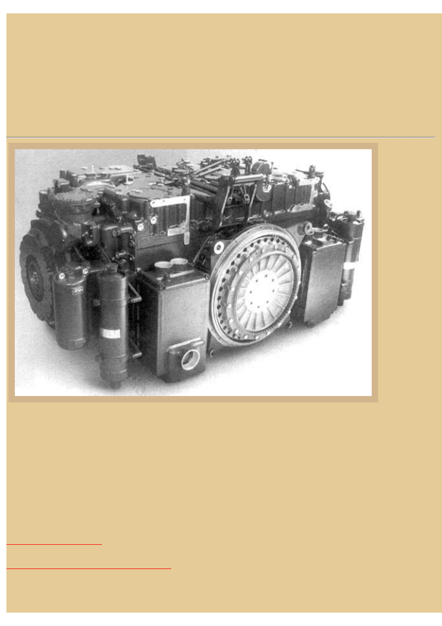
Picture 9:
The Renk
HSWL 354
Transmission
is a monster
itself,
particularly
when
disconnected
from the
powertrain
and setting on
the floor like
this.
Operation is
full and semi-
automatic,
and
mechanical
brakes are
built on the
output shafts,
which are
transverse to
the input, as you see here. Steering drive is infinitely variable by a hydrostatic-hydrodynamic superimposed steering
system. The transmission brake is a combined hydrodynamic-mechanical brake system as service brake, without
parking and auxiliary brakes. Most of the components you see on this front end are concerned with the central oil
supply, consisting of built-in reservoirs, pumps, filters, and valves. There is also a connection for the oil heat
exchanger. Keep in mind that the control for gear shifting and reversing is electrical, the driver's control box is the
remote control unit. On the other hand, mechanical actuation is necessary for steering, service brake, and emergency
drive second gear forward and reverse, when the electrical current fails. Weight of the unit alone is around 70,000kg
Both the Dutch and Swiss also have used the Leopard 2 as their MBT. With its strong combination and balance of
excellent mobility, tremendous firepower, and armor protection, the Leopard 2 is clearly one of the finest main battle
tanks fielded today.
BACK TO AFV INTERIORS HOME PAGE
(c) 2003, AFV INTERIORS Web Magazine
file:///H|/Modellismo/AFV%20Interiors/[armor]%20-%20AFV...Interiors/afvinteriors.hobbyvista.com/leop2/leop2a.html (7 di 7)07/02/2007 22.17.17
file:///H|/Modellismo/AFV%20Interiors/[armor]%20-%20AFV%20Interiors/afvinteriors.hobbyvista.com/leop2/leop2b.html
Leopard 2 Main Battle Tank, Part 2
Picture 1:
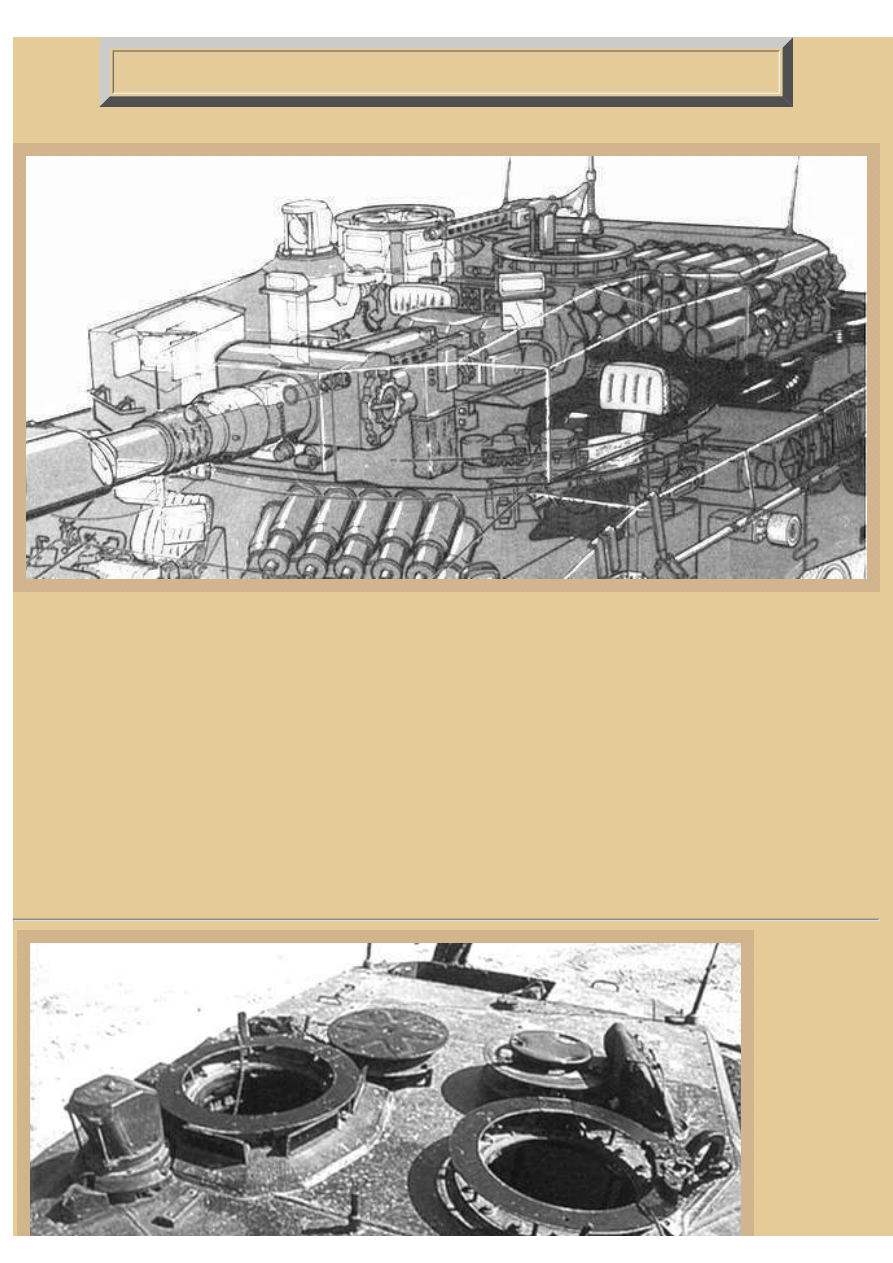
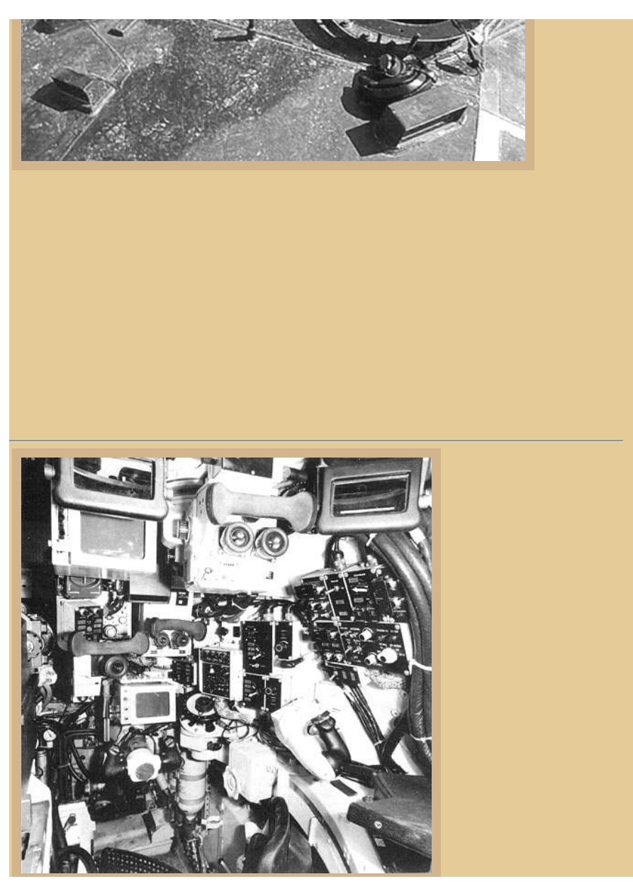
We are continuing on our examination of the interior of the German Leopard 2 tank up in the turret. The commander
on the right side of the gun is provided with a circular hatch cover that opens to the rear and periscopes for all round
observation. A PERI-R17 panoramic periscope is located just forward of his hatch. The gunner, who sits just in front
of the commander, has a stabilized EMES-15 sight with integrated laser rangefinder and thermal image unit, linked to
the fire control computer. He also has an auxiliary sighting telescope. The commander uses the thermal sight,
integrated with the gunner's EMES-15, to observe the battlefield. The picture is transmitted to the commander's
panoramic periscope to he can see the same view as the gunner. The gunner also has an auxiliary telescope FERO-Z18
with a magnification of 8x, the telescope seen here wedged in between the primary sight and the main gun.
The loader occupies the area to the left of the gun, with the coax MG directly in front and ammo storage in the turret
bustle bin directly behind. Like the M1 Abrams tanks, the Leopard 2 was designed with the turret ammunition
contained in a blast proof ammo bin, accessed by the loader through blast doors normally kept closed.
Picture 2:
Climbing out
on top of the
turret we have
this view of the
commander's
(on the left) and
loader's
hatches. Notice
the different
methods of
opening and
securing the
/2007 22.17.17
file:///H|/Modellismo/AFV%20Interiors/[armor]%20-%20AFV...Interiors/afvinteriors.hobbyvista.com/leop2/leop2b.html (1 di 12)07/02
file:///H|/Modellismo/AFV%20Interiors/[armor]%20-%20AFV%20Interiors/afvinteriors.hobbyvista.com/leop2/leop2b.html
hatches. As
with the
Leopard 1, the
commander's
still uses a gas
cylinder assist
for opening his
lid, and there
are no obvious
handles on the
inside surface. The loader's heavy hatch is assisted with the more typical spring mounted between the hinges, and the
inside surface has a handwheel that latches secures it when closed. Notice also the commander's panoramic sight,
forward and to the right of his position, partially obscuring his view, and the gunner's viewing periscope, located a bit
further forward, at the lower-left in the picture. The loader's single periscope is also visible here at the lower right,
angled toward the front-left corner of the turret (with a German tanker's helmet lying behind). As we have also seen
with the Leopard 1, both turret hatches are double layered, and each has a skate ring for the mounting of a machine
gun (MG3). When closing them, both hatches swing over the skate rings before dropping down into their openings.
The Germans were hoping to procure a purchase contract from the Americans for their original Leopard 2 design, but
after trials it was mildly criticized as not meeting their needs in the area of armor protection and fire control. To meet
the US requirements, the new design was changed to incorporate a new and better-protected turret with different
sighting and gun laying components. This newly revised Leopard 2, at that time called the Leopard 2AV, then became
the standard for the actual production version. This process was taking place at the same time as trials in the US with
the Chrysler and GM entry into the XM1 program, and in the end the US utilized their own design for their next battle
tank, and the Germans kept their new Leopard 2 design.
Picture 3:
If we drop down into the
commander's open hatch in the
original Leopard 2 (not the
production version), this would be
the view we would have looking
forward into the turret. In view is
the basic layout of the gunner's
(forward) and commander's
positions (to the right). Centered
above is an early PERI-R-12
commander's sight with
gyrostabilised sightline. To the
left of this and also immediately
above the gunner's handgrips, are
the matte screens of the night
sight monitor displays, by means
of which the commander and
gunner can observe the battlefield
together or independently, and
can acquire and engage targets.
Above and to the right of the
gunner's monitor is an EMES-12
stereoscopic rangefinder sight,
while to the left of it is a TZF 1A
auxiliary sighting telescope. On
/2007 22.17.17
file:///H|/Modellismo/AFV%20Interiors/[armor]%20-%20AFV...Interiors/afvinteriors.hobbyvista.com/leop2/leop2b.html (2 di 12)07/02
file:///H|/Modellismo/AFV%20Interiors/[armor]%20-%20AFV%20Interiors/afvinteriors.hobbyvista.com/leop2/leop2b.html
the turret wall to the right is an
operating panel for the FLER-H
fire control computer, an operating mode select, an operating panel for the target searchlight, and a brightness control.
Directly above the commander's gun-laying control handle (right) is a commander's control panel, from which he can
operate the smoke pots, grenade launchers, and in emergency situations fire the gun, de-ice the sights, wash the
exterior lenses of the optics, and operate the night vision devices. When the older style turret was replaced with the
more heavily armored block style before mass production, most of these sights and fire controls were revised with
updated version, as we shall see.
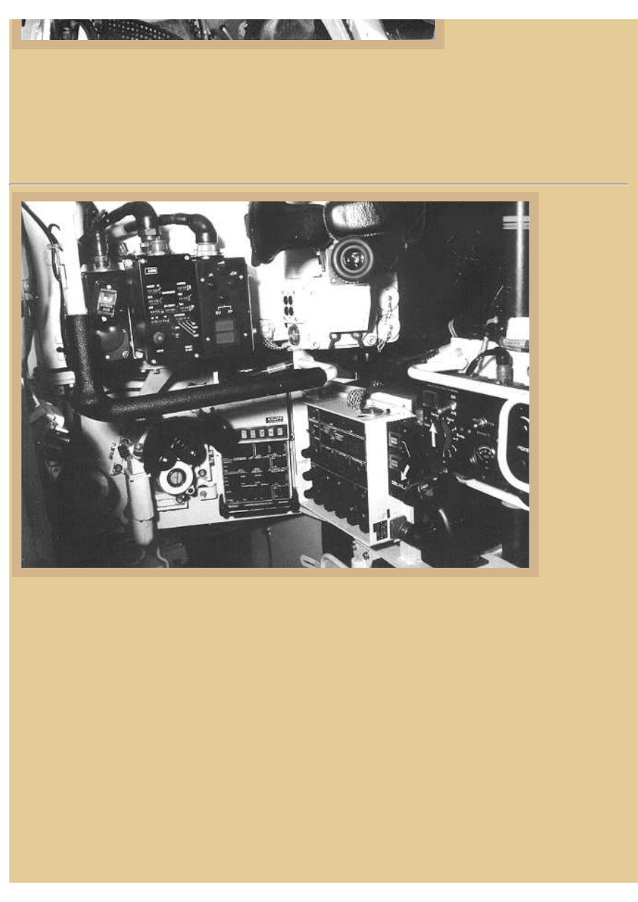
Picture 4:
With
acceptance of
the new T19/
T20 turret
design, one of
the interior
component
updates was the
substitution of a
ruby laser
rangefinder for
the stereoscopic
unit. This is the
interior of a
typical Leopard
2A1-A4
production
version. The
new EMES-15
gun-laying and
stabilisation
system is an
improved
version of the
earlier EMES-12, and consists of a dual-magnification, stabilized, binocular primary sight with integrated ruby laser
rangefinder and Zeiss Eltro Optronik thermal sight, all linked to the tank's fire control computer. The solid state sight
and laser rangefinder unit is the gunner's binocular eyepiece seen at the lower left with control panels to the right. The
rangefinder is said to be capable of determining three range values in about four seconds. All of this information is fed
into the computer system and monitored by the gunner using this one sight unit. In the picture, you can also just barely
see the gunner's backup FERO A18 8X articulated telescopic sight at the far lower left, although it is mostly in
shadows here. Along the left edge of the picture is the side of the big 120mm gun; there is barely room for the
telescope between the EMES sights and gun mount.
The commander uses his PERI-R17 (A1 and A2 in subsequent upgrades) 360-degree panoramic periscope (2x/8x),
also from Zeiss, for day or night sighting and target acquisition (seen here in the upper portion of the photo). Eight
periscopes surround his cupola to provide a 360-degree field of view around the tank. The commander's gun laying
and firing handgrip is at the lower right, but it is difficult to see the black handle with the black controls panels behind.
As with most modern Western MBT's, the commander's gun laying controls can over-ride the gunner's inputs in an
emergency. The general operation drill for the Leopard 2 has the commander searching and finding threat targets using
his eight periscopes and panoramic periscope, and then handing them off one at a time to the gunner to kill using his
EMES 15. While the gunner is fine aiming and firing the weapon, the commander is once again free to search for
additional targets. By the way, the radio equipment in use since the Leopard 2 A3 has been the SEM 80/90 radio
/2007 22.17.17
file:///H|/Modellismo/AFV%20Interiors/[armor]%20-%20AFV...Interiors/afvinteriors.hobbyvista.com/leop2/leop2b.html (3 di 12)07/02
file:///H|/Modellismo/AFV%20Interiors/[armor]%20-%20AFV%20Interiors/afvinteriors.hobbyvista.com/leop2/leop2b.html
system.
Picture 5:
Here are the major components of the EMES 15 (actually, called the STN ATLAS Elektronik FLT-2/EMES 15 Tank
Fire Control System-- TFCS) used on the production Leopard 2. The gunner's primary sight (1) is located at the front
right corner of the turret, with the gunner's control unit (2) next to his sight. The commander also has a control unit (3)
and a display unit (4) up at his position, and there is also a computer control unit (5), a commander's hand control (6)
and the main digital ballistic computer (7) located back in the turret bustle along with the radio set. The crosswind
sensor (8) was later dropped as unnecessary, but the gun elevation sensor (9) is also shown in the drawing as well as
the laser electronics box (10), and vertical (cant angle) sensor (11).
Picture 6:
This is a Krauss-Maffei promotional photo
of the EMES 15 gunner's sight, from the
side this time. The exposed periscope head
is the green box at the upper right, and the
gunner's optic eyepieces are extended
down and to the lower left. The long
extension tubes from the periscope head to
the gunner's optics are necessary due to
the sight box being located at the front-
right corner of the redesigned turret, some
distance forward of the gunner's seat.
/2007 22.17.17
file:///H|/Modellismo/AFV%20Interiors/[armor]%20-%20AFV...Interiors/afvinteriors.hobbyvista.com/leop2/leop2b.html (4 di 12)07/02
file:///H|/Modellismo/AFV%20Interiors/[armor]%20-%20AFV%20Interiors/afvinteriors.hobbyvista.com/leop2/leop2b.html
The laser rangefinder included in the
EMES 15 is a Zeiss-Eletro Optronik
thermal sight, model WBG-X, and both
units are linked to the tank's fire control
computer. The thermal sight is said to
utilize standard US Army common
modules, with a 120-element cadmium
mercury telluride (CdHgTe) infrared
detector array, operating in the 8 to 14
micron wavelength band. The detector's
heat is cooled by a built-in closed-cycle
cooling engine (infrared detectors get very
hot, very quickly, as there is a lot of
energy required for operation).
The sight is also fitted with a CE628 laser rangefinder from Eltro GmbH and is a solid state Neodymium Ytrinium
Aluminum Garnet set (Nd:YAG), the laser offered in eyesafe and non-eyesafe configurations. Maximum range for the
laser rangefinder is advertised at just under 10,000 meters, with accuracy of around 10 meters. Our thanks to
Alexander Lyakhovetsky for providing some of this additional information about the sight, infrared detector, and
rangefinder systems, back when the first addition of this page was published in 1998.
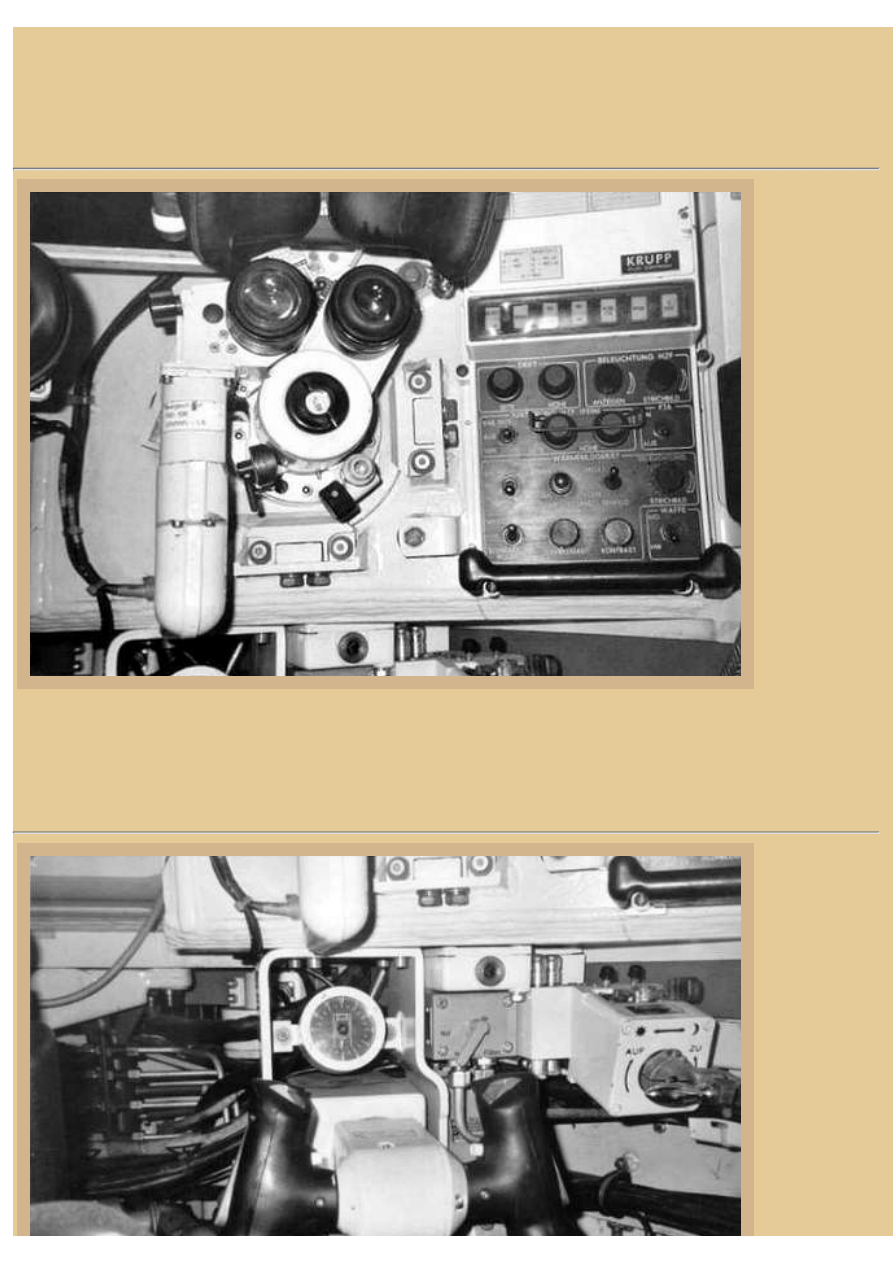
Picture 7:
This is a close-up view of the
EMES 15 gunner's sight control
panel and optics. The forehead
pads are above the eyepieces, and
you may have noticed that the
right eyepiece is adjustable to fit
different eye center distances. I
am afraid that except for the
name "KRUPP", I can not read
most of the labels on the gunner's
control labels. But a couple of
them are clear enough to read on
the EMES control panel, to the
right of the oculars. The upper
left two, under the row of
pushbuttons, are "DRIFT", and
the two upper right knobs are
labeled "BELEUCHTUNG", or
lighting/illumination. The next
lower group of controls and
knobs are labeled
"JUSTIERUNG HZF", which
means adjustment, and there are
knobs for "FEIN" and "GROSS".
Further down are controls for the
sight heater, and contrast
adjustment. At the bottom right is
the knob to switch between
"WAFFE", or weapons, MG and
main gun being the options.
/2007 22.17.17
file:///H|/Modellismo/AFV%20Interiors/[armor]%20-%20AFV...Interiors/afvinteriors.hobbyvista.com/leop2/leop2b.html (5 di 12)07/02
file:///H|/Modellismo/AFV%20Interiors/[armor]%20-%20AFV%20Interiors/afvinteriors.hobbyvista.com/leop2/leop2b.html
Perhaps someone else with access to clearer images or personal knowledge will help us with these controls. The
EMES day vision sight is promoted as having a zoom capability up to 12x, and the thermal image produced for the
gunner and commander can be set to either 4x or 12x. The auxiliary sighting device is the monocular FERO-Z18
(Leitz) telescope with an 8x zoom, which you can see off to the left.
Picture 8:
The
stabilization of
the EMES is
independent
from the gun
stabilization so
that the gun is
lead by the fire
control
computer using
the visible line
of the EMES.
The fire control
computer
(FLT2)
processes the
distance to the
target, the
movement of
the target and
of the Leopard
2, the altitude,
wind, air and
ammunition temperature. It then compares this data with the vision line of the optical device in use (EMES or PERI)
and controls the hydraulic turret rotation and gun elevation/depression WNA-H22 (by AEG) to compensate and match
the conditions. All of this is done very quickly, and the sight reticle does not move from the target during the process.
Once the go light illuminates, the gunner fires the weapon and prepares for the next shot.
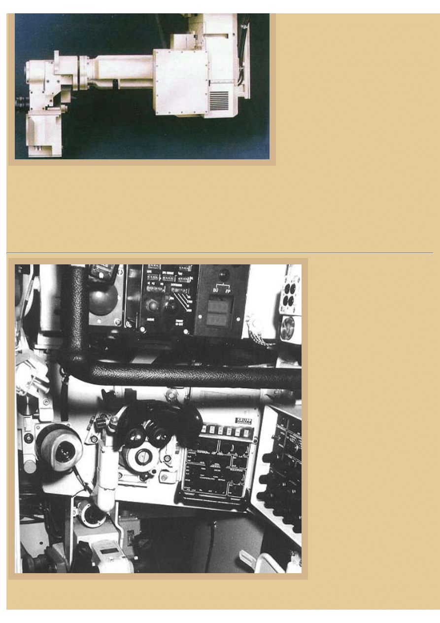
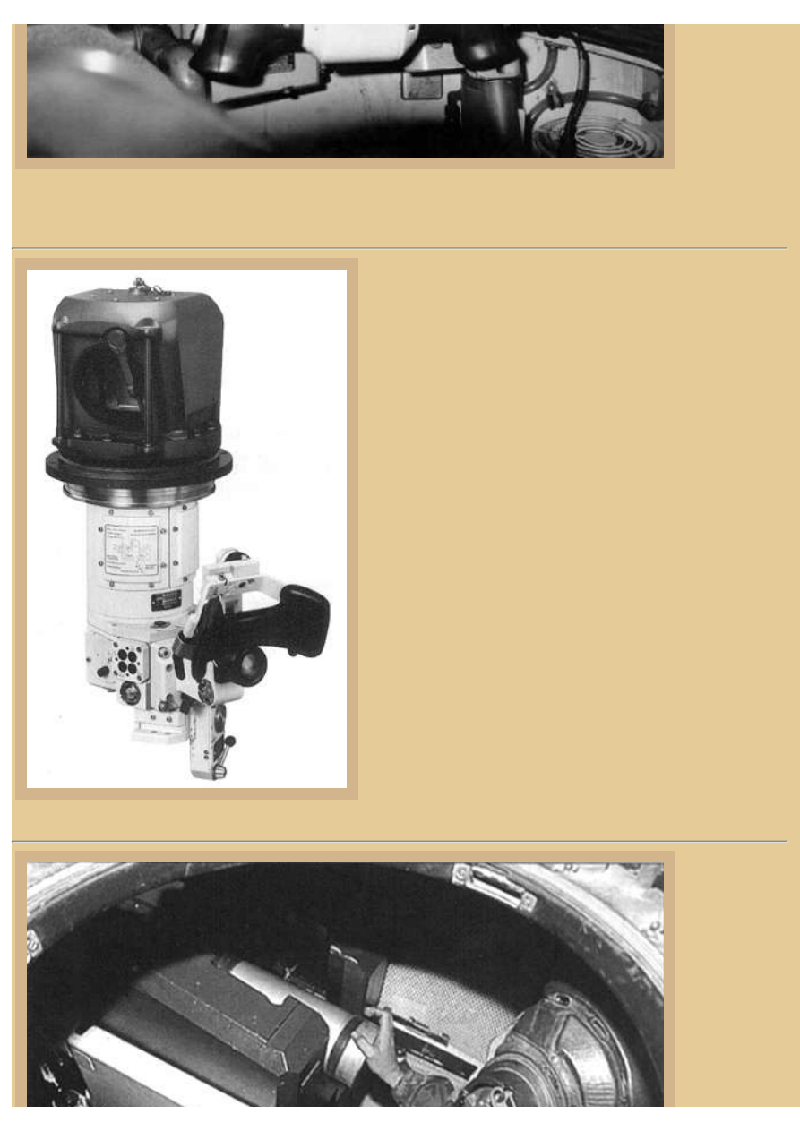
Picture 9:
A closer view
of the gunner's
equipment
below the sight
unit illustrates
additional
details. His gun
laying hand
grips are clearly
seen; rotating
them backward
or forward
elevates or
depresses the
turret, and
turning them
/2007 22.17.17
file:///H|/Modellismo/AFV%20Interiors/[armor]%20-%20AFV...Interiors/afvinteriors.hobbyvista.com/leop2/leop2b.html (6 di 12)07/02
file:///H|/Modellismo/AFV%20Interiors/[armor]%20-%20AFV%20Interiors/afvinteriors.hobbyvista.com/leop2/leop2b.html
clockwise or
counter-
clockwise
traverses the
turret in either
direction. To
the right of the
handgrips is the day or night switch for his sight, and directly above the grips is a small azimuth indicator. At the top
of the picture is the lower portion of the gunner's EMES 15 sight box and controls that we saw in the previous picture.
Picture 10:
This is a promotional photo of the PERI-R17A1 commander's
panoramic periscope as used in later Leopard 2 tanks,
manufactured by STN Atlas Elektronik and Zeiss Optronik
GmbH. The PERI-R17 used in early Leopard 2 tanks was
similar in most respects. These sights are two-axis, gyro-
stabilized, digital, 360-degree periscopes that can be used by the
commander for general observation, target identification, or
target tracking and firing. There are two switch selectable
magnifications of 2x and 8x available, and the panoramic
periscope may be used independently by the commander, or
integrated into the vehicle's fire control system to view what the
gunner is seeing. Aiming the panoramic sight is via a standard
NATO pattern reticle with adjustable brightness control. The
collimator markings are also used for boresighting, and there is a
direct viewing adapter for thermal image projection, as we have
seen in some of our pictures, that looks like a small television
screen.
Picture 11:
This is the view
looking down
through the
loader's open
hatch with the
breech ring of
the big 120mm
L44 gun in
plane view. The
gun is loaded
by hand, which
/2007 22.17.17
file:///H|/Modellismo/AFV%20Interiors/[armor]%20-%20AFV...Interiors/afvinteriors.hobbyvista.com/leop2/leop2b.html (7 di 12)07/02
file:///H|/Modellismo/AFV%20Interiors/[armor]%20-%20AFV%20Interiors/afvinteriors.hobbyvista.com/leop2/leop2b.html
is not an easy
proposition as
the rounds are
long and heavy.
But a good
loader can feed
the breech
every six
seconds or so
when things get
hectic, pulling
the called-for
rounds out of the bin behind and swinging around to punch them into the open breech in front. However, you typically
won't find a loader punching the round home with open fingers like you see here, as the breech is unforgiving when
closing on fingers. Like the Leopard 1, there is a fume scavenging system attached to the spent shell catch bag located
below the weapon, so fumes from the steel cartridge stub (most of the shell is self-consuming upon firing) can be
quickly removed from the turret.
A total of 42 rounds of 120mm ammo is stored in the Leopard 2 A1 through A5, and for the coaxial 7.62mm MG there
are around 4800 rounds. A FlaMg 7.62mm MG is available for one of the hatch skate rings, and a further 3800 rounds
are available for this weapon. There are also eight smoke dischargers mounted on the turret, four each side, and they
may be fired singly or in volleys.
Picture 12:
The 120mm L/44 gun has a vertical "drop" breech block and the loading mechanism is hydraulically assisted--
necessary because the one-piece rounds are so darn heavy. This is a Rheinmetall photo showing the 120mm weapon in
its rectangular mount that allows a depression of -10 degrees and an elevation of +20. The weapon fires two basic
types of ammo, APFSDS-T (Armor-Piercing Fin-Stabilised Discarding Sabot Tracer), DM-13 and DM-23 KE
(Kinetische Energy), and later also the DM-53, and a HE said to be of the HEAT-MP-T (Multi-Purpose Tracer)
variety DM-12 MZ (Mehrzweck = multipurpose) that can be used against armor, soft-sided targets, support infantry,
bunkers, etc.
The cartridges are mostly self-consuming, leaving only the steel cartridge stub (the last 5 inches or so of shell). Self-
consuming stubs take up less space in the turret after firing, and more can be held in the catch bag under the breech.
The inside bore sleeve of the 120mm gun is chromium plated to add some extra life to the system. If this all sounds
vaguely familiar... the US M1A1/2 uses an almost exact copy of this same weapon. There is a coaxial 7.62mm MG3
mounted to the left of the cannon and 42 120mm rounds, 27 in the forward magazine bin and the other 15 in the left
side of the turret bustle, and separated from the fighting compartment and the loader by an electrically operated door.
The turret bustle magazine is equipped with blow-off panels in the roof, and if the magazine were hit the doors would
direct the resulting explosion upward and away from the crew. On early models of the Leopard 2, there was a small
hatch on the left turret wall for assisting with the task of reloading, but it was welded shut on 2A3 models and omitted
on later vehicles as it produced a weak spot on the turret armor and leaked.
/2007 22.17.17
file:///H|/Modellismo/AFV%20Interiors/[armor]%20-%20AFV...Interiors/afvinteriors.hobbyvista.com/leop2/leop2b.html (8 di 12)07/02
file:///H|/Modellismo/AFV%20Interiors/[armor]%20-%20AFV%20Interiors/afvinteriors.hobbyvista.com/leop2/leop2b.html
Picture 13:
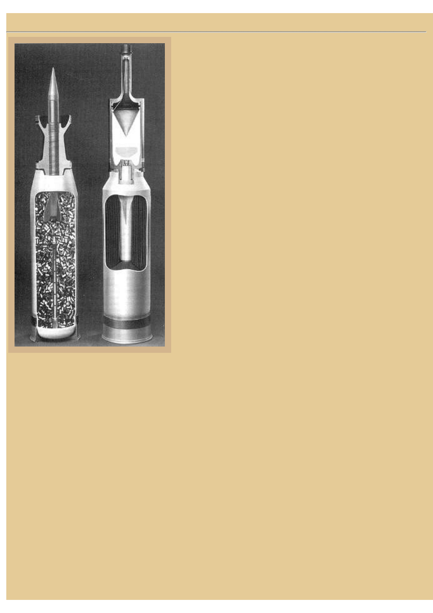
A promotional photograph from Rheinmetall shows both the APFSDS-
T and HEAT-MP ammunition with cut-away shell casings. As
mentioned previously, the cartridge cases are combustible with the
exception of the base, which is made of steel and contains the primer.
The most popular APFSDS-T round is the DM33, seen on the left; the
earlier versions of the fin-stabilized discarding-sabot round were the
DM13 and DM23. The illustration clearly shows the long rod
penetrator with its attached fins, as well as the discarding sabot
surrounding most of the penetrator and providing a tight fit in the gun
tube for speed and stability. Note the grooves around the penetrator
that hold the sabot until after the round leaves the gun barrel and the
sabot peels away. Also in the photo you can see the pellet-type
propellant inside the cartridge case, with the primer rod extending up
through the pellets for more precise ignition.
The round on the right is the HEAT-MP-T (MZ) known as the DM12.
The projectile consists of a body filled with a shaped charge and
equipped with a piezoelectric sensor, a base detonating fuze, and a tail
assembly containing the tracer element. As you can see, the cartridge
case is filled with stick propellant. Note the conical shape of the
shaped charge, which helps form the flame that burns through the
armor target, and the standoff extension of the shell tip that insures the
correct distance between the warhead and the armor when the flame
cutter begins to form.
Perhaps this is a good time to take a few minutes and examine the
ballistic properties of a typical shaped charge projectile. In short, the
shaped charge consists of a high explosive charge packed around a
conical metal liner. The charge is initiated at the base so that the
detonating wave moves through the explosive toward the apex of the
cone. As the detonating wave meets the apex and then moves along it towards its base, the metal liner collapses
inwards. The metal is forced from all points towards a common center, from where it flows into a jet that is moving
perpendicular from the apex of the cone.
At this point we come upon one of the strangest parts of the shaped charge story. During this collapsing process, the
metal from the liner does not change its state. That is, it remains a solid rather than a liquid. But the solid material has
such a high energy that it flows hydrodynamically-- it flows as if it were a liquid. The tip of a jet is now formed from
the metal at the apex of the cone, and it travels at a velocity in the region of 8000-9000m/s, depending on the
detonation velocity of the explosive that originally surrounded the cone. As the circumference of the cone expands, the
explosive has to act on an increasing mass of metal, and as a result, the energy of the liner per unit area decreases
towards the base of the cone, and the metal is driven towards the center with decreasing energy. Most of the metal still
continues to flow into the jet, but with steadily decreasing velocity, and this results in the elongation of the jet. Some
of the metal is unable to flow into the jet, and so collects at the center, forming a slug that is relatively massive and
slow moving compared to the jet. The overall result is an elongated jet of metal flame with the tip moving at 8000-
9000m/s and the tail at approximately 2000m/s, followed by a slug travelling much more slowly, at something
between 300 and 800m/s.
What happens when the jet strikes the armored target? The super-heated jet causes the metal of the target surface to
flow away from the point of impact, gradually forming a hole into which the jet continues to strike. This happens
extremely fast, and as the tip of he jet penetrates the armor, metal from the jet flows continuously to coat the surface of
the hole, consuming the jet as it penetrates. As the tip of the jet is consumed, it is replaced by slower moving metal,
and if the entire jet is consumed without achieving a penetration in the armor the relatively massive slug following
/2007 22.17.17
file:///H|/Modellismo/AFV%20Interiors/[armor]%20-%20AFV...Interiors/afvinteriors.hobbyvista.com/leop2/leop2b.html (9 di 12)07/02
file:///H|/Modellismo/AFV%20Interiors/[armor]%20-%20AFV%20Interiors/afvinteriors.hobbyvista.com/leop2/leop2b.html
along behind passes into the cavity and becomes lodged.
If the jet does completely penetrate the armor, the residual jet and the slug passes into the interior of the target and
damages whatever is in its path. The jet is also accompanied by spall from around the hole of the penetrated armor. If
the armor is massively overmatched by the warhead, the jet may continue to have sufficient energy to pass straight
through the opposite side of the vehicle, as some were seen to do in Iraq when M1A1 Abrams tanks fired into the
turret sides of Iraqi T-72s. On the other hand, if the jet is only marginally successful, it may barely penetrate the
armor, with little resulting physical or physiological damage inside the vehicle. Recall that the underlying beauty of
the shaped charge is that high velocity of the round is not necessary, indeed is not desirable, and therefore a shaped
charge weapon may be fired from a man portable tube or rocket launcher. Under ideal conditions, a shaped charge will
penetrate a thickness of RHA of about five times the diameter of the shaped charge cone. Remember that this rule of
thumb does not work for laminated armor, as it has been designed to dissipate the shaped charge jet and accompanying
energy.
Picture 14:
The Leopard 2 has proved to be a very successful export venture for the German arms industry, and to this point
around 3200 vehicles have been exported. Receiving countries include Austria, Denmark, the Netherlands, Norway,
Switzerland, Sweden and Spain, with over 3200 produced. The Finnish Army is buying 124 Leopard 2 tanks and the
Polish Army 128 used Leopard 2A4 tanks from Germany (imagine that!). In March of 2002, the Hellenic Army of
Greece announced that it had selected the Leopard 2 GR, with a requirement for 170 tanks.
This image is a publicity sketch showing the recent upgrade armor package provided for the Leopard 2A5. One of the
main differences in turret layout between the A1-A4 and the newly armored A5 is the location of the commander's
panoramic periscope (which now also houses a thermal sight). Its original position to the right front of the
commander's cupola partially obscured his vision, so the sight mount was moved to the left rear of the cupola. With
the panoramic periscope move came the problem of locating his viewing optics in a convenient location at the front of
2007 22.17.17
file:///H|/Modellismo/AFV%20Interiors/[armor]%20-%20AF...nteriors/afvinteriors.hobbyvista.com/leop2/leop2b.html (10 di 12)07/02/
file:///H|/Modellismo/AFV%20Interiors/[armor]%20-%20AFV%20Interiors/afvinteriors.hobbyvista.com/leop2/leop2b.html
his cupola. A long lens tube system was developed that brings the image from the periscope body around the left side
of his hatch opening and then curves it back to end at his optics located in the space between his cupola's forward
viewing block and the first left viewing block. Another major change that arrived with the 2A5 is a new driver's hatch
that is now electrically operated, sliding to the right to provide access.
Picture 15:
The resulting
arrangement of
the
commander's
panoramic
periscope
optics in
relationship
with the cupola
viewing blocks
is illustrated in
this photo taken
looking down
toward the front
of his hatch
opening. The
video screen is
part of the
EMES 15
system, and his
viewing blocks
and the optics
of the
panoramic
periscope are
clearly visible.
Down below you can see the extensive recoil screening between the commander's position and the 120mm gun, there
being no chance the weapon will hit the commander upon recoil if the screens are left intact. The gunner's seat is seen
below, directly in front of the commander's position.
Picture 16:
The latest
version of the
Leopard 2 is
the 2A6 which
includes a
longer L/55
gun, an
auxiliary
engine,
improved mine
protection, and
an air-
conditioning
2007 22.17.17
file:///H|/Modellismo/AFV%20Interiors/[armor]%20-%20AF...nteriors/afvinteriors.hobbyvista.com/leop2/leop2b.html (11 di 12)07/02/

file:///H|/Modellismo/AFV%20Interiors/[armor]%20-%20AFV%20Interiors/afvinteriors.hobbyvista.com/leop2/leop2b.html
system. The
German Army
is currently
upgrading 225
2A5 tanks to
the 2A6
configuration,
the first of
which was delivered to them in March of 2001. The Royal Netherlands Army has also ordered the upgrade of 180 of
its 2A5 tanks to the 2A6 configuration, the first of which was delivered in September of 2001. An additional 219
Leopard 2A6s are to be license-built in Spain by General Dynamics, Santa Barbara Sistemas (GDSBS). This is an
interesting state of affairs as General Dynamics (parent of the M1 Abrams) has, through their acquisition of Santa
Barbara Sistemas in 2001, gained additional expertise building their biggest competitor's tank. The Leopard 2 has truly
been a remarkable tank design, and has become the "Eurotank" as originally intended by its designers some thirty odd
years ago. This photo is courtesy Krauss-Maffei Wegmann GmbH.
My thanks to the late Dr. Dieter Houser from Germany for providing many of the images for this series, and also to
Mr. Stefen Kotsch, who has helped us before with our interior projects, particularly the T-72. Mr Kotsch's own web
page,
, contains a comprehensive introduction to some of the world's modern battle tanks, from
the outside out. Some of the interior images we used in these pages can be found in larger color format at his site.
Thanks again Stefen for your support. Any errors in these pages are my own.
BACK TO AFV INTERIORS HOME PAGE
(c) 2003, AFV INTERIORS Web Magazine
2007 22.17.17
file:///H|/Modellismo/AFV%20Interiors/[armor]%20-%20AF...nteriors/afvinteriors.hobbyvista.com/leop2/leop2b.html (12 di 12)07/02/
Document Outline
Wyszukiwarka
Podobne podstrony:
AFV Interiors Water Buffalo
Afv Interiors Isu 152
AFV Interiors CV 33 35
AFV Interiors German AFV Radio Equipment In WWII
AFV Interiors M1A2 Abrams
AFV Interiors British Medium Tank Mk I & Mk II
AFV Interiors Czech Light Tank, LT vz 38, Pz Kpfw 38(t)
Afv Interiors Daimler Scout Car
AFV Interiors Otter
AFV Interiors B1 bis
Afv Interiors Mk V
AFV Interiors Marder III
AFV Interiors M113 Toa
AFV Interiors Fahrpanzer
AFV Interiors Semovente Da 75 18
AFV Interiors LVT
AFV Interiors IS 2
AFV Interiors Flakpanzer 38t
Afv Interiors Medium Tank Mark A whippet
więcej podobnych podstron