PRZEGL!D ELEKTROTECHNICZNY (Electrical Review), ISSN 0033-2097, R. 86 NR 10/2010 203
Lech GRODZKI
Bialystok Technical University - Faculty of Electrical Engineering
Constant-current driving of the LEDs' group
Abstract. Some LED applications need parallel driving of the groups of diodes. The article presents few selected chips designed to constant-current
LED driving. The paper contains the description of main properties of those integrated circuits and some results of realised research works on their
application features. Because the presented devices have SPI interface, they can be controlled by supervising microcontroller. The paper also
contains the proposal of automotive application, as the component of modern vehicle electrical system.
Streszczenie. Artyku! prezentuje kilka wybranych uk!adów scalonych przeznaczonych do sta!opr"dowego sterowania diodami LED. Obok
prezentacji cech u#ytkowych tych uk!adów, zawarto tak#e wybrane wyniki bada$ aplikacyjnych, zwi"zanych z wykorzystaniem interfejsu SPI do ich
sterowania przez mikrokontroler. Artyku! zawiera równie# propozycj% aplikacji uk!adów tego typu w nowoczesnej instalacji elektrycznej samochodu.
Ci!g"o-pr!dowe sterowanie grupowe diodami LED
Keywords: constant-current LED driving, LED group working, microcontrollers
S!owa kluczowe: sta!opr"dowe sterowanie LED, praca grupowa diod LED, mikrokontrolery
Group driving of LED diodes
Some LED applications are based on simultaneous
control of few or more devices. For example, they are used
for back-lighting other devices (like LCD displays,
illuminating advertising panels, etc.) or they perform
information functions directly, like traffic lights, road signs,
information panels, etc. In simplest case, LED driving
circuits in those applications have to switch on and off the
whole groups of LED devices. More advanced applications
need also the possibility of dimming the lighting sources.
That last feature allows to automatic control of emitting light
flux, according to external conditions, like external
illumination or the time of a day.
If group driving demands only simple switch on-off
features, without any brightness control, the driving circuits
can be reduced to bi-stable transistor valves. The
brightness control feature needs more complex circuits. To
achieve this feature, a PWM control of switching power
transistor has been applied, form many years [1, 2]. The
value of pulse width coefficient defines the switch-on and
switch-off periods of LED group. Increasing of that
coefficient causes the higher brightness of emitting light.
This dimming control idea is based on human eyesight
sense features: integrating light pulses and limited fast
event notification.
In last years some IC manufacturers started deliver the
integrated devices, which can control the constant current
supplying the LED. Such devices allow to more precise
control of LED brightness. Especially, integrated circuits
controlling few or more LED simultaneously are very
interesting for group LED driving.
Group driving ICs - general characteristics
Texas Instruments elaborated the series of integrated
circuits dedicated to the control of work of groups of LED
diodes. Among others, company offers either chips with 8
output channels - TLC5916/17 or 16 output channels -
TLC5926/27 [3, 4]. The characteristic feature of those ICs is
application of N controlled current sources, with commonly
adjusted current efficiency. Output current adjustment can
be realised in two ways:
1. By the change of the external resistor R
EXT
we can
define the maximum value of current source efficiency,
common for the all of outputs, according to formula:
(1)
EXT
OUTMAX
R
V
,
I
15
25
1
!
"
The internal construction and power dissipation
possibilities limit the range of output current I
OUTMAX
to
the range: 5 - 120 mA.
2. By sending via serial interface appropriate configuration
byte (Fig. 1). That byte determines the fraction of
maximum output current value I
OUTMAX
, defines by
formula 1, which states the present efficiency of current
sources. That fraction, called current gain (CG), can take
256 discrete values among the range: 1/12-127/128,
according to the following formulas.
(2)
#
$
%
&
'
(
)
)
"
64
1
4
1
CC
HC
VG
(3)
1
3
*
!
"
CM
VG
CG
where: CM, HC and 6-bit word CC are components of
the configuring byte.
After power-up devices work with default values:
CM
= 1, HC = 1, CC = 111111b. It means that CG equals
0,992 and causes maximum output current value
I
OUTMAX
, limited by external resistor R
EXT
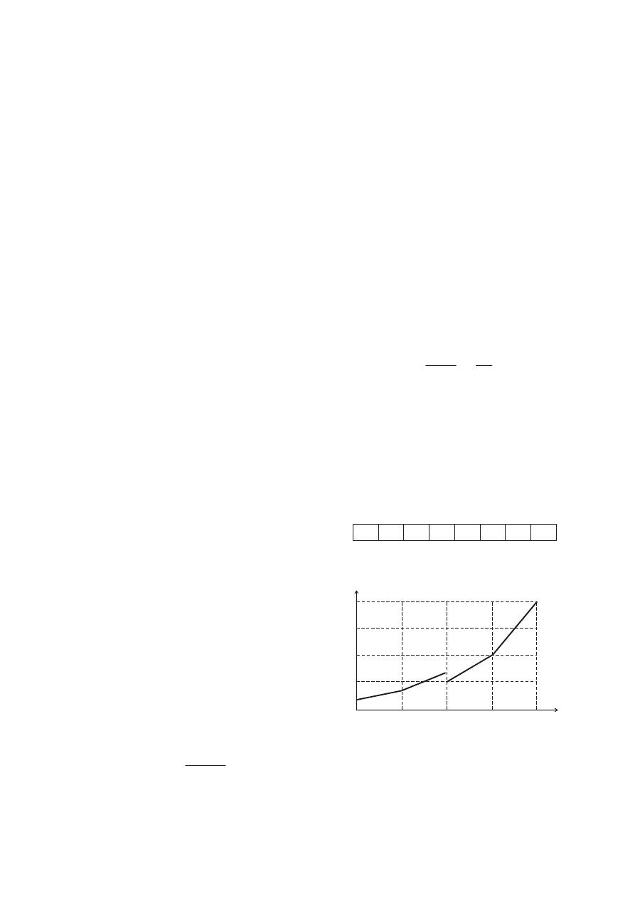
. Figure 2 shows
the value of current gain CG depending on the value of
configuration byte with constant value of external
resistor R
EXT
.
Fig.1. Configuration byte of TLC5916/17
Fig.2. Current gain (CG) versus value K of configuration byte
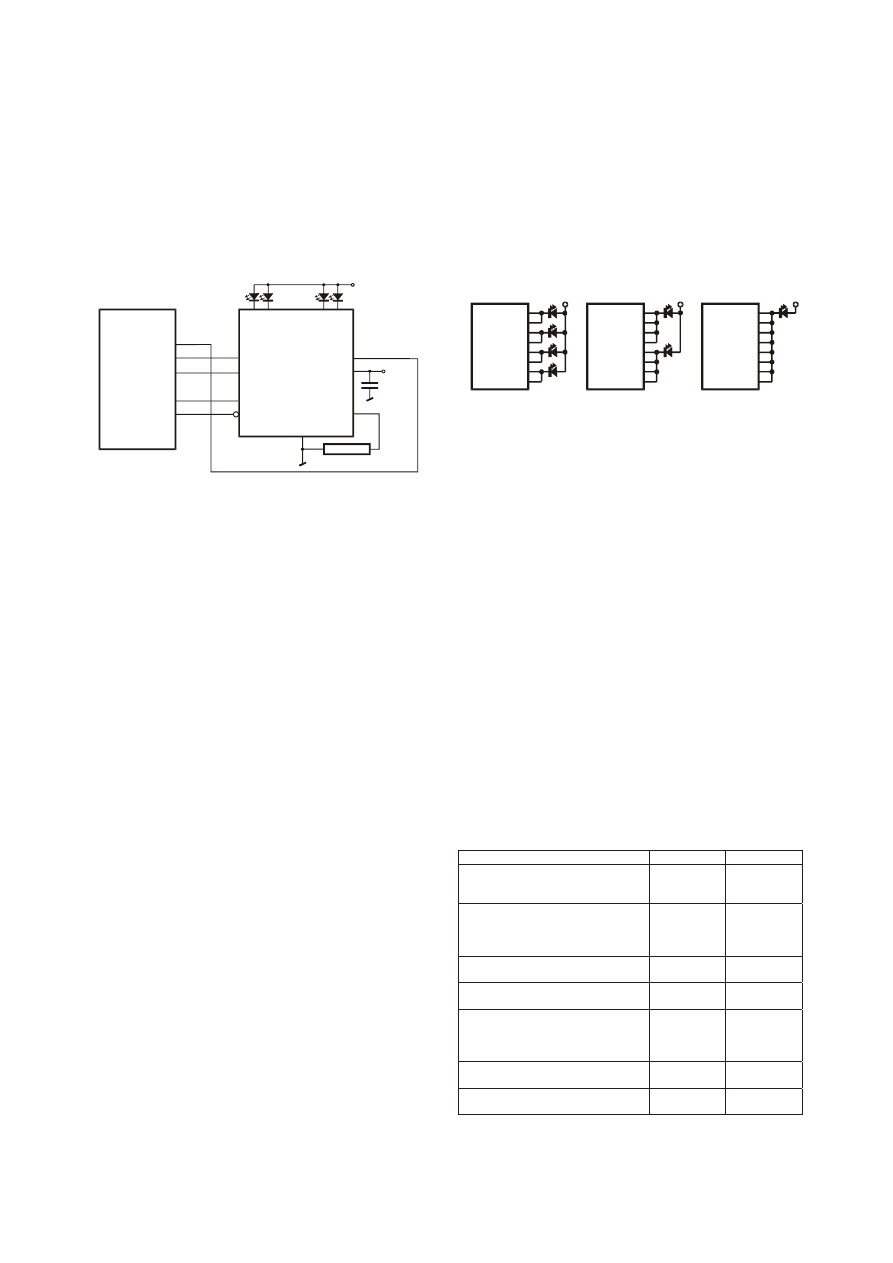
The utilization of the second method is possible only in
cooperation with supervising processor. Figure 3 shows the
testing circuit, used in described research works. It's a
typical application circuit for that family of integrated
devices. Microcontroller can manage the devices via serial
synchronous interface looking like SPI. This interface is
64
128
192
255
0,992
0,750
0,500
0,250
0,083
0
K
[-]
0
CG
[-]
CM
HC
CC
5
CC
4
CC
3
CC
2
CC
1
CC
0
204 PRZEGL!D ELEKTROTECHNICZNY (Electrical Review), ISSN 0033-2097, R. 86 NR 10/2010
used to transfer to IC driver on-off control word, switching
outputs OUT
X
, and configuration byte. The same interface
allows to read out the device status word, containing the
information about detected malfunctions of the output
channels. Control circuits of current sources can detect
following errors, separately for each channel:
+ open circuit - too low value of output voltage for
switched-on channel;
+ over-temperature shutdown in working output channel -
too high temperature of output circuit in given channel;
+ LED short-circuit - too high value of voltage for
switched-on output (only TLC5917 and TLC5927 ICs).
Fig.3. Testing circuit applied during research works
During simultaneous control of group of LED devices,
we try to achieve the same working points, as the condition
of steady brightness of several diodes. For presented IC
drivers manufacturer guarantees quite good output current
accuracy: ±3% between channels in the same chip and
±6% between different ICs. There are satisfied values,
looking at the typical divergence of LED working
characteristics.
Adjusting the LED forward current
In last capture two ways of output current adjustment
are pointed:
+
hardware method, by the changes of external resistor;
+
software method, utilizing the configuration byte
transferred to driver IC via serial interface.
The both methods allow to precise adjustment of LED
forward current. But the second of them is more suitable,
even though it needs the supervising microcontroller.
In practice, software method can realised in two ways:
1. External resistor R
EXT
is set to the value giving I
OUTMAX
current equal the needed LED forward current I
FLED
. It
causes that any configuration byte with value differ to
11111111b, written to IC driver will decrease the LED
current. We achieve the possibility of fluent control only
during dimming of LED group connected to the chip
output channels.
2. The value of the external resistor R
EXT
is set less then it's
described above. In such situation, the optimum LED
forward current I
FLED
we can achieve at current gain CG
less then 0,992 (I
FLED
< I
OUTMAX
). Then, before the
switching on the outputs OUT
X
, we should send to the IC
driver appropriate configuration byte, decreasing the
value of output currents I
OUT
. Presented solution results
in the less number of dimming steps, but also allows for
increasing the LED current over the chosen working
value. The possibility of occasional increasing the LED
luminance, can be very useful in some applications. For
example, if it is important to achieve the constant
luminance contrast between the vehicle signalling lamp
and the external lighting, it would be possible to
increase the luminous flux while the external luminance
flux reaches high values.
According to the application note [5], it’s possible to
point one another way of the output current adjustment,
especially useful for POWER LEDs. Even though the
maximum output current of each channel is equal 120 mA,
for driving of POWER LED devices it can be insufficient. In
such case, driver outputs can be connected in parallel, to
obtain controllable output current up to I
NOUTMAX
=
N
·120 mA. Using 8-channel TLC5916/17 ICs we can control
the 4, 2 or 1 POWER LED, up to 960 mA, according to their
forward currents - figure 4.
Fig.4. Possible POWER LED control configurations in order to their
forward current: a - up to 240 mA; b - up to 480 mA; c - up to
960 mA
In this way, we achieve additional method of POWER
LED current adjustment: simultaneous change the current
gain and the number of working paralleled channels. For
fluent dimming in wide range of LED forward current it's
sufficient to select the number of switched on channels and
the value of configuration byte. That additional POWER
LED current adjustment method widens the application
fields of presented IC drivers.
Selected results of tests
Data sheets of presented IC drivers states, that
maximum frequency of serial interface clocking signal is
equal 30 MHz. In practice, according to defined transfer
frame, does not matching fully to SPI standard, data
exchange between microcontroller and IC LED driver
should be realised under software control. The suitable
testing software, written in machine language, had been
prepared for testing circuit from figure 3. Programmes were
debugged and tested in IDE AVRStudio. The realised tests
with supervising microcontroller ATmega8515, clocked
frequency 10 MHz, allow to estimate software transfer
speed. Execution times of most important control operations
for TLC5916/17 and TLC5926/27 are presented in table 1.
Table 1. Execution time of selected software-implemented
operations for TLC5916/17 i TLC5926/27
Operation
TLC5916/17
TLC5926/27
control word transfer
(8b for TLC5916/17, 16b for
TLC5926/27)
11,1 #s
23,1 #s
configuring word (with current gain
coefficient) transfer
(8b for TLC5916/17, 16b for
TLC5926/27)
10,6 #s
16,3 #s
switching working mode from normal
to special
4,1 #s
4,1 #s
switching working mode from
special to normal
3,7 #s
3,7 #s
setting special working mode and
read out the error word
(8b for TLC5916/17, 16b for
TLC5926/27)
16,6 #s
26,2 #s
switching the LED group using /OE
signal
0,3 #s
0,3 #s
minimum period of SPI clocking
signal SCLK
0,4 #s
0,4 #s
SDI
CLK
LE
OE
SDO
VDD
REXT
O
U
T
0
O
U
T
1
:
:
:
O
U
T
6
O
U
T
7
G
N
D
PB6/MISO
PB5/MOSI
PB7/SCK
PB4
PB3
U
LED
R
EXT
U
CC
100nF
ATmega8515
TLC5916/17
U
LED
TLC5916/17
a)
U
LED
TLC5916/17
b)
U
LED
TLC5916/17
c)
OUT0
OUT1
OUT2
OUT3
OUT4
OUT5
OUT6
OUT7
OUT0
OUT1
OUT2
OUT3
OUT4
OUT5
OUT6
OUT7
OUT0
OUT1
OUT2
OUT3
OUT4
OUT5
OUT6
OUT7
PRZEGL!D ELEKTROTECHNICZNY (Electrical Review), ISSN 0033-2097, R. 86 NR 10/2010 205
The analysis of the table contents leads to a conclusion
that: for 8-channel driver switching word and configuration
byte can be updated about 90000 times per second. The IC
with 16 outputs is served slower.
Three of the mentioned in table 1 operations can be
supported by hardware SPI interface. It give us a shorter
execution times, as it is shown in table 2.
Table 2. Execution time of some operations using hardware SPI
interface for TLC5916/17 i TLC5926/27
Operation
TLC5916/17 TLC5926/27
control word transfer
(8b for TLC5916/17, 16b for
TLC5926/27)
5,7 #s
9,4#s
configuring word (with current
gain coefficient) transfer
(8b for TLC5916/17, 16b for
TLC5926/27)
6,6 #s
10,3 #s
setting special working mode and
read out the error word
(8b for TLC5916/17, 16b for
TLC5926/27)
14,0 #s
18,2#s
Application proposal
One of the possible applications of presented LED IC
drivers is their usage in vehicle signalling lamps. The aim is
designing, for instance, car STOP lights with ability of self-
adjusting their luminance, according to changing ambient
conditions, to guarantee the optimal luminance contrast
between activated signalling lamps and other vehicle lights
or ambient luminance. It should be noted, that adaptive
signalling vehicle lamps are already allowed by international
standards [6]. The concept of such car lamp was described
among other in [7]: proposed solution can be realised on
the base of local analog-digital circuit, adjusting the light
source supply voltage. The usage of local microcontroller
and IC LED driver really increases the construction
functionality.
TLC59xx
,C
SPI
CAN
12V
LS1
LS2
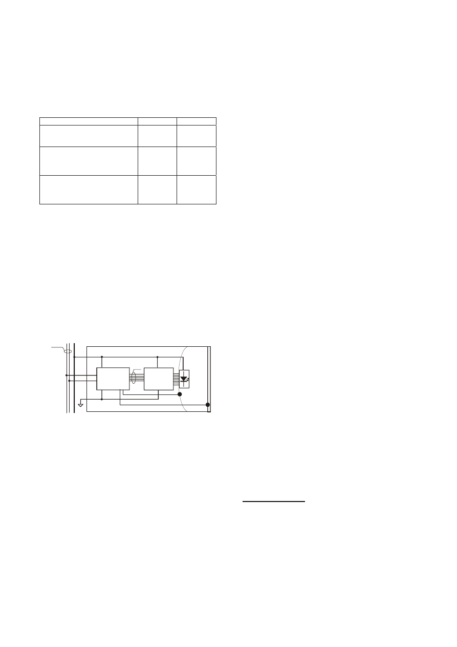
Fig.5. The proposal of intelligent vehicle signalling lamp
In proposed solution (Fig. 5) local microcontroller is
connected with LED driver by SPI interface. Using that
interface microcontroller sends to LED driver orders to
control the light source (switch on, switch off, brightness
adjustment), according to orders, received via CAN bus
from supervising computer.
Using the local light sensors LS1 and LS2 [7] and the
messages from CAN bus, microcontroller decides about
LED current adjustment. In addition, using the features of
TLC59xx chips, it can test the efficiency of group of LEDs.
As it was described earlier, troubles, like short break,
short-circuit, over-temperature shut down, in any output
channel are indicated in read out status word. This
information should be transfer to the vehicle central
computer. It can be also used locally to adjust the light
source, by increasing the currents in others active LED
supplying channels, to maintain the ordered luminance flux.
Suggested automotive application of TLC59xx family chips
can be applied also in classical electrical vehicle net. In that
case, local microcontroller of signal lamp should trace the
state of dedicated signal line instead the receiving
messages via CAN bus.
Conclusion
Integrated circuits providing constant current supplying
LEDs are offered by others manufactures, too. For
example, National Semiconductors offers several ICs, but
those chips have only single [8] or no more then few [9]
controlled outputs. In addition their applications need some
discrete external elements, like resistors, capacitors and
coils. Moreover, LED brightness adjustment is realised by
PWM signal provided to special terminal of ICs. Integrated
LED drivers with 8 or 16 output channels are also offered by
Allegro MicroSystems [10]. But embedded SPI interface
allows only for switching and checking LED diodes.
Dimming is possible only using additional PWM control
signal.
Watching the broadening offer of LED constant current
IC drivers, it is possible to suppose, that those chips will find
durable place for themselves in the wide range of LED
applications.
Presented results are the part of research work No S/WE/1/06.
REFERENCES
[1] Wojtkowski W.: Wielokana!owa regulacja jasno$ci $wiecenia
diod LED z wykorzystaniem uk!adów programowalnych FPGA.
Przegl"d Elektrotechniczny, 85 (2009), nr 11, 310-312.
[2] Wojtkowski W.: Wykorzystanie sprz%towych bloków PWM
mikrokontrolerów AVR do regulacji jasno$ci $wiecenia diod
LED du&ej mocy. Przegl"d Elektrotechniczny, 85 (2009), nr
11, 306-309.
[3] Texas Instruments: TLC5916, TLC5917 8-bit constant-current
LED sink drivers. Datasheets on www.ti.com. 2008.
[4] Texas Instruments: TLC5926, TLC5927 16-bit constant-
current LED sink drivers. Datasheets on www.ti.com. 2008.
[5] Day M.: LED driver - Paralleled Outputs Provide High-Current
Outputs. Application report on www.ti.com. 2006.
[6] Mo'ko W., Ka(mierczak P., )ukasik M.: Luminance contrast of
vehicle signalling lamps. Przegl"d Elektrotechniczny, 85
(2009), nr 11, 272-275.
[7] )ukasik M.: The concept of the wheeled vehicle's adaptive
stop lamps operation. Przegl"d Elektrotechniczny, 84 (2008),
nr 8, 186-189.
[8] National Semiconductors: LM3402/LM3402HV 0.5A constant
Current Buck Regulator for Driving High Power LEDs.
Datasheets on www.national.com. 2008.
[9] National
Semiconductors:
LM3432/LM3432B
6-Channel
Current Regulator for LED Backlight Application. Datasheets
on www.national.com. 2008.
[10] Allegro
MicroSystems:
Constant-Current
LED
Drivers.
Application Information AN29503 on www.allegromicro.com.
2007.
Author: dr in#. Lech Grodzki, Politechnika Bia!ostocka, Wydzia!
Elektryczny, ul. Wiejska 45D, 15-351 Bia!ystok, E-mail:
lgrodzki@we.pb.edu.pl
Wyszukiwarka
Podobne podstrony:
Constant current driving of the LEDs group
Constant current driving of the RGB LED
Constant current driving of the RGB LED
Edge of the Empire Group Sheet
fitopatologia, Microarrays are one of the new emerging methods in plant virology currently being dev
Consolidated Financial Statements of the Group & Bank Mellat
Legg Calve Perthes disease The prognostic significance of the subchondral fracture and a two group c
Melin E The Names of the Dnieper Rapids in Chapter 9 of Constantine Porphyrogenitus De administrando
Dan Mills Sniper One The Blistering True Story of a British Battle Group Under Siege (rtf)
Soliwoda, Katarzyna i inni The influence of the chain length and the functional group steric access
Pavsic Clifford Algebra of Spacetime & the Conformal Group (2002) [sharethefiles com]
Geoffrey de Villehardouin Memoirs or Chronicle of The Fourth Crusade and The Conquest of Constantin
THE GHOST SHIP Current state of research and project plan for maritime
Eringer Robert, The Global Manipulators, The Bilderberg Group Trilateral Commission Covert Power Gro
Measurements of the temperature dependent changes of the photometrical and electrical parameters of
Future Of The Dollar As World Reserve Currency Forbes
Aspden The Theory of the Proton Constants (1988)
więcej podobnych podstron