
13
Solar Drying
La´szlo´ Imre
CONTENTS
Solar-Assisted Dryer Combined with Heat Pump and Heat Storage......................... 317
Solar-Assisted Dryer Integrated into a Complex Energy System ............................... 317
Heat Storage Charged by the Medium of the Collector............................................. 333
ß
2006 by Taylor & Francis Group, LLC.

Direction of the Operation of Chimney-Type Solar Dryers ....................................... 348
Direction and Control of Solar Dryers with Rock-Bed Heat Storage ....................... 351
Automatically Controlled Solar Dryer with Auxiliary Heater ................................... 351
Direction and Control of Solar Dryers with Water Storage ...................................... 352
Nomenclature ................................................................................................................................................. 355
References ...................................................................................................................................................... 356
13.1 INTRODUCTION
Open-air sun drying has been used since time imme-
morial to dry plants, seeds, fruits, meat, fish, wood,
and other agricultural or forest products as a means of
preservation. However, for large-scale production the
limitations of open-air drying are well known. Among
these are high labor costs, large area requirement, lack
of ability to control the drying process, possible deg-
radation due to biochemical or microbiological reac-
tions, insect infestation, and so on. In order to benefit
from the free and renewable energy source provided by
the sun several attempts have been made in recent
years to develop solar drying mainly for preserving
agricultural and forest products.
13.2 ASPECTS AND LIMITATIONS
OF SOLAR DRYING
13.2.1 G
ENERAL
C
ONSIDERATIONS
Among the advantages of solar drying one may cite a
free, nonpolluting, renewable, abundant energy source
that cannot be monopolized [1]. At the same time, in
using solar radiation for planned drying, several diffi-
culties must be overcome. There is the very basic prob-
lem of the periodic character of solar radiation, a
problem that gave rise to the idea of storing part of
the energy gained during radiation periods. This diffi-
culty can be eliminated, aside from employing heat
storage devices, only with the use of an auxiliary energy
source. Even the radiation periods may produce certain
difficulties. First, the intensity of incident radiation is a
function of time. This is a circumstance that demands
adequate control strategy and the means necessary for
the control. Another problem is caused by the low
energy density of solar radiation, which requires the
use of large energy-collecting surfaces (collectors).
Thus, the nature of solar radiation has innate
problems that require means (heat stores, auxiliary
energy source, control system, and large-surface
solar collectors) for their solution, and so the invest-
ment costs are considerable. Obviously, a prerequisite
to utilizing solar energy is economics and the need to
achieve an acceptable rate of return.
An examination of the technoeconomics of solar
drying has led to the knowledge of the main factors,
their roles, and influencing mechanisms. The first
obvious discovery was that solar energy can be eco-
nomically used for drying only if the purpose can be
coordinated with the specific characteristics of solar
radiation. Thus, geographic circumstances deciding
the number of sunny days yearly and the incident
radiation intensity give different energy gain in various
areas of the Earth. The relatively small energy flux
density of solar radiation implies that it is particularly
suited to drying processes with small energy demands.
Seasonal changes of solar radiation suggest the use
of solar drying in the maximum radiation intensity
season: e.g., part of the agricultural products should
ß
2006 by Taylor & Francis Group, LLC.

be dried during this period [202]. Matching of the
drying process and the specific characteristics of
solar radiation is also important in governing the
investment costs. Because of the small flux density
of solar radiation, a high-temperature drying medium
can only be produced with concentrating collectors.
Such collectors are generally very expensive. Cheaper,
flat-plate collectors, on the other hand, can be applied
only for producing a moderate-temperature medium
(usually under 608C), and their efficiency improves
with a decrease in operation temperature. So dryers
with flat-plate collectors can be used for products
requiring low-temperature drying.
One way to reduce the costs of solar collectors is
to strive for cheap and simple construction. This can
mean a decrease in operation life and efficiency so
that the task must be handled as an optimization
problem. Another possibility is multipurpose con-
struction, for instance, building the collector into the
roof structure as an integrated part.
At this point technical development can proceed in
two directions: simple, low-power, short-life, and com-
paratively low-efficiency dryers in one direction, and
high-efficiency, high-power, long-life, expensive dryers
in the other direction. The latter are characterized not
only by an integrated structure but also by integration
in an energy system involving processes other than
drying. The aim is twofold: coupling a solar energy
dryer to a farm’s energy system gives the possibility of
using solar collectors practically throughout the whole
year, for example to produce hot water when the dryer
is not in use; also, the hot water tank of the farm can be
used as a heat store of the solar system.
13.2.2 R
OLE AND
I
MPORTANCE OF
S
OLAR
D
RYING IN THE
D
EVELOPING
C
OUNTRIES
Due to the lack of adequate preservation methods,
direct open-air drying is still a widely used means of
food preservation in most parts of the developing
world [147,152]. This traditional practice has its in-
herent disadvantages:
Damage to the crop by rodents, birds, and animals
Degradation through exposure to direct irradi-
ation of the sun and to rain, storm, and dew
Contamination by dirt, dust, wind-blown debris,
and environmental pollution
Splitting of the grain bleaching and loss of
germination capability due to overdrying
Insect infestation
Growth of microorganisms
Additional losses during storage due to insuffi-
cient or nonuniform drying
Postharvest losses can be estimated at more than
30% [148,149] and it could be reduced to a great
extent by adequate drying of crops [150].
There are two possible ways for the proper pre-
servation by drying: by using fossil fuels and by using
solar energy. Not considering the disadvantageous
environmental pollution effects caused by the CO
2
,
SO
2
, and NO
x
emission, the use of fossil fuel fired or
electrically powered dryers is limited and inappropri-
ate for most of the farmers in developing countries.
The main reasons are as follows:
Expensive investment and high energy costs
Lack of skilled personnel for operation and
maintenance
Conventional sources of energy are either unavail-
able or unreliable [151]
During the last decades, several developing coun-
tries have started to change their energy policies to-
ward further reduction of petroleum import and to
alter their energy use toward the utilization of renew-
able energies [152].
With very few exceptions, the developing coun-
tries are situated in climatic zones of the world
where the insolation is considerably higher than the
world average of 3.82 kWh/m
2
day [153]. In Table 13.1
daily average horizontal insolation data and sun-
shine hours are given for some developing countries
[152,154].
TABLE 13.1
Total Horizontal Solar Insolation and Sunshine
Hours for Some Developing Countries
Country
Average Insolation
(kWh/m
2
day)
Sunshine
Hours (h/d)
Cameroon
3.8–5.5
4.5–8.0
Egypt (Cairo)
6
9.6
Guatemala
5–5.3
—
India
5.8
8–10
Indonesia
4.24
—
Kenya
5.25–5.6
6–7
Malaysia
4.41
—
Mali
4.34
8.4
Mauritius
4.5
7
Mexico (Jalapa, Veracruz)
4.65
—
Nicaragua
5.43
—
Nigeria
3.8–7.15
5–7
Papua New Guinea
4.6–9.6
4.5–8
Philippines (Metro Manila)
4.55
—
Sierra Leone
3.4–5.3
3–7.5
Thailand
4.25–5.66
—
Togo
4.4
5.5–7.2
ß
2006 by Taylor & Francis Group, LLC.
An alternative to traditional drying techniques
and a contribution toward the solution of the open-
air drying problems is the use of solar drying. The
main reasons are as follows [216]:
1. Solar drying provides the desired reduction of
losses together with improved quality of the
dried products.
2. The time of drying can be significantly reduced.
3. The harvesting period can be shortened, which
enables the soil to be prepared for the cultiva-
tion of another crop.
4. The drying season can be lengthened by succes-
sive harvests and by using solar dryers in which
various types of products can be preserved.
5. Farmers may have a greater income by the
production of marketable crops.
6. The additional costs involved in installing solar
dryers can be returned by the increased profits.
Accordingly, the availability of solar energy and the
operational marketing and economy reasons offer a
good opportunity for using solar drying all over the
world. A great number of successful practical appli-
cations
have
already
been
reported
[152,155–
174,206,211,215,217].
13.3 CONSTRUCTION PRINCIPLES
OF SOLAR DRYERS
13.3.1 M
AIN
P
ARTS OF
S
OLAR
D
RYERS
Solar dryers have the following main parts:
1. Drying space, where the material to be dried is
placed and where the drying takes place
2. Collector to convert solar radiation into heat
3. Auxiliary energy source (optional)
4. Heat transfer equipment for transferring heat
to the drying air or to the material
5. Means for keeping the drying air in flow
6. Heat storage unit (optional)
7. Measuring and control equipment (optional)
8. Ducts, pipes, and other appliances
13.3.2 C
LASSIFICATION OF
S
OLAR
D
RYERS
The structure of solar dryers is adjusted to the quan-
tity, character, and designation of the material to be
dried as well as to the energy sources used. Accord-
ingly, a great variety of solar dryers have been devel-
oped and are in use. The following classification
suggests three main groups for solar dryers on the
basis of the energy sources used [175]:
1. Solar natural dryers using ambient energy
sources only
2. Semiartificial solar dryers with a fan driven by
an electric motor for keeping a continuous air
flow through the drying space
3. Solar-assisted artificial dryers able to operate
by using a conventional (auxiliary) energy
source if needed
13.3.3 S
OLAR
N
ATURAL
D
RYERS
In the main group of solar natural dryers two sub-
groups are included: the subgroup of the passive,
natural convection solar dryers (cabinet, tent type,
greenhouse type, chimney-type dryers) and the sub-
group of active, partly forced convection solar dryers
having a fan driven by electric energy converted by
photovoltaic solar cells [226] or driven by a small
wind turbine.
13.3.3.1 Cabinet Dryers
The simplest solar dryers are the cabinet dryers (Fig-
ure. 13.1). Their main characteristic is that the heat
needed for drying gets into the material through dir-
ect radiation and through a south-oriented, transpar-
ent (glass or foil) wall 1. Other walls of the dryer are
opaque and well insulated. The drying material 2 is
spread in a thin layer on a tray 3. The bottom plate of
the tray is perforated. Air flows through the holes by
natural convection through the material and finally
leaves through the upper part of the cabinet [2,3]. The
design of the dryer is simple, and its cost is low. It is
suitable for drying small quantities (10–20 kg) of
granular materials (e.g., for individual farmers). The
products dried in cabinet dryers are mainly agricul-
tural products—vegetables, fruits, spices, and herbs.
South
1
Air
out
3
2
Air
in
FIGURE 13.1 Structure of a cabinet dryer. (From Special
issue, Sunworld, 4, 179, 1980; Garg, H.P., in Proceedings of
the Third International Drying Symposium (J.C. Ashworth,
Ed.), Drying Research Limited, Wolverhampton, England,
1982, p. 353.)
ß
2006 by Taylor & Francis Group, LLC.
Drying of the material can be mad e more even by
periodi c turnin g over of the mate rial. It is employ ed
chiefly in tropi cal countri es, but during the war m
months it can be used in the tempe rate climates as
well. The usu al size of the drying area is 1–2 m
2
) .
A varia tion of the cabinet drye r is the tent dryer,
which con sists of a triangular framew ork covered
with a thin sheet (Figur e 13.2a) . The south- oriented
front wall 1 is trans parent; the back wall is co vered by
a black sheet. The material is sp read on a tall tray
made of ne tting or wi re mesh.
Ano ther type of tent dryer has its roof covered by
polyet hylene sheet. The dry ing mate rial is spread ov er
a concret e floor (e.g., c offee bea ns) [2]. Ano ther type
of the tent dryer is the terrace dry er. Its cross- section
is sketche d in Fi gure 13.2b [2]. The drying shelve s
1 stand on posts 2; the ro of and the front wall are
covered wi th a polyet hylene foil 3. Cer tain types of
terrace dryers are made with ro ofs that ope n so that
under favora ble weather cond itions the dr ying mate r-
ial is exposed to direct radiat ion. Const ructing tent
and terr ace dryers is cheap a nd simp le. They are
widely used for drying coffee. In Colombia, abou t
70% of the coffee bean s are dried in such dryers [2].
13.3.3 .2 Nat ural Conve ction , Static Bed,
or Shelf- Type Dryers
The capacit y pe r unit area of ca binet dryers is limited
by two co nditions: need for direct radiation on the
drying material and smal l airflow rate. To dry large r
quantities of mate rial, the basic area of the dryer ha s
to be increa sed. To avo id this pro blem it is preferab le
to place the material in severa l indepen dent layer s; the
necessa ry heat transfer is thus accompl ished by con -
vection . The increa se in the mass flow rate of air can
be achieve d by increasing the effects that produce
natural conv ection. These effects must a lso be in-
crease d if the air is to be circulated through a material
laid in severa l layer s one over the other, or through a
thick layer, as in the case of the stat ic be d type. To
keep up the na tural pressur e difference wi thout using
a ventilator (for instance, in a field), the ‘‘chimney
effect’’ must be exploited. For this purpose the verti-
cal flow of hot air in the dryer must be increased.
In Figure 13.3 a scheme of the so-called shelf dryer
can be seen [4]. The material to be dried is placed on
perforated shelves 1 built one above the other. The
front wall of the case faces south, its top and sides
2 are covered by transparent walls (glass or sheet),
3
2
1
(a)
3
3
1
1
2
3
(b)
FIGURE 13.2 Cabinet dryer variations: (a) tent-type dryer; (b) its terrace-type solution. (From Special issue, Sunworld, 4,
179, 1980.)
2
5
2
4
South
Air
out
3
1
Air in
FIGURE 13.3 Shelf-type dryer with separate collector. (From Wibulswas, P. and Niyomkarn, C., Reg. Workshop on Solar
Drying, CNED-UNESCO, Manila, 1980, p. 1.)
ß
2006 by Taylor & Francis Group, LLC.

and the back wall 3 is heat insul ated. The back wal l
and the floor are co vered with a coating of black
paint. The ambie nt air is war med in a flat-pl ate col-
lector 4 joined to the bottom of the case, and it flows
up to the space unde r the lowest shelf. M oist air exit s
to the open throu gh the upper ope ning of the case 5.
In the scheme shown in
is en sured by the increa sed height (approxi mate ly
1 m). Test measur ement s ha ve shown that over a
period of 5 y the be st resul ts wer e obtaine d wi th the
aid of a glass -cover ed absorber plate placed in the
middle of the air opening. Cost s of utilized energy
(Thaila nd climate, January–A pril) amount to abo ut
U.S. $.03/ kWh. The experimen ts indica ted that sep-
aration of the c ollector is only justified with a high-
efficien cy collector. The dryer is suit able for drying
fruit and vegeta ble good s. (For a theoret ical analys is
of she lf-type solar dryers, see Ref . [5].)
For large amou nts of mate rial to be dried the
airflow rate through the dryer should be increa sed.
In case of static bed-ty pe solar dry ers an a ppropri-
ately high ch imney has to be connected to the dr yer
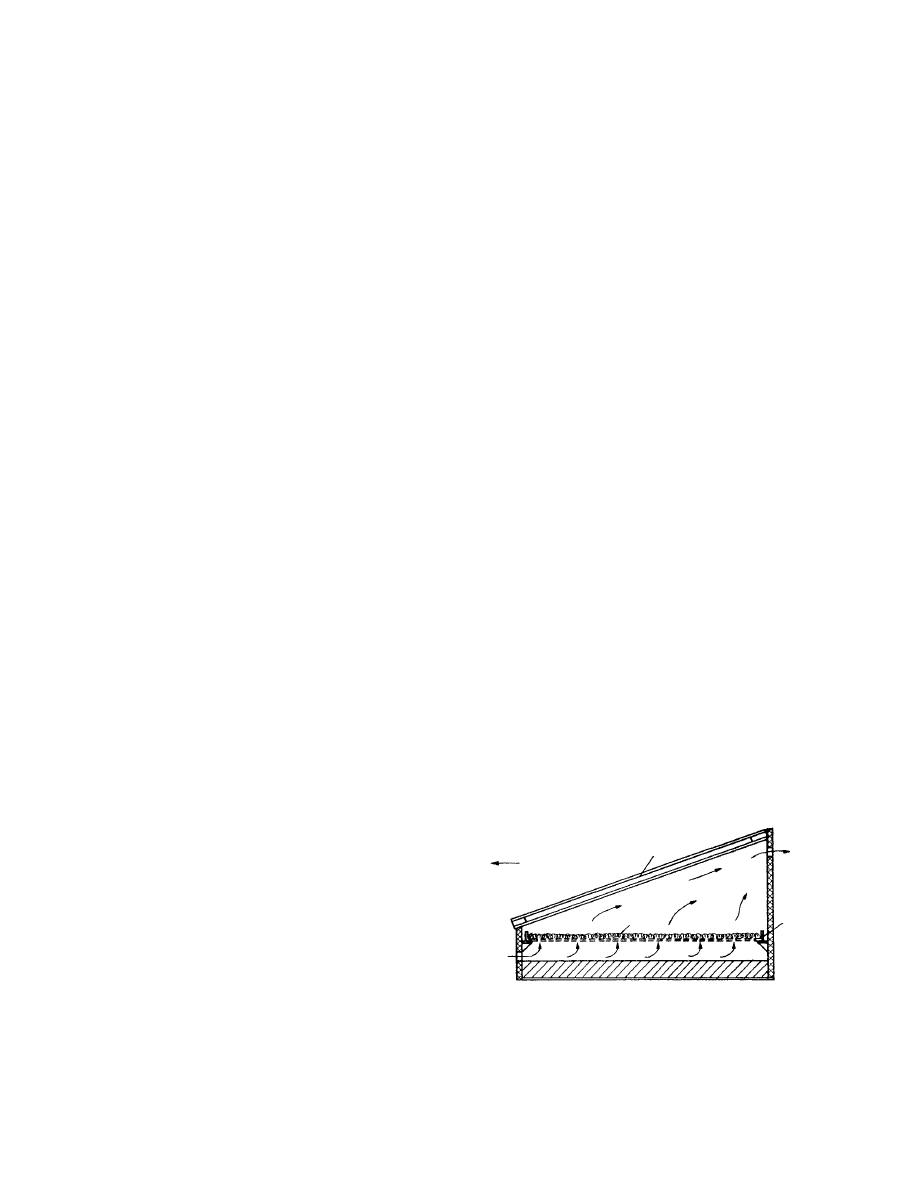
housing [204]. Figu re 13.4 gives the cro ss-section of a
chimney -type dryer designe d and built for drying
1000-kg rice [2]. Rice is placed in a static bed I in a
0.1-m thick layer. The co llector 2 co nsists of a plast ic
coveri ng and roasted rice shell, the latter playi ng the
role of absorber . The front surfa ce 3 over the layer of
rice is also trans parent. The wall of the chimney 5 is
made of black plastic foil. The framew ork of the dr yer
is wood an d wire; manu facture is inexpensiv e and
simple. The air needed for drying amounts to
5.7 m
3
/min per m
3
rice. The chimney is 5 m high .
Drying is not uni form, so the rice in the static bed
must be turned ov er at intervals . The dur ation of
drying is 3–4 d in the case of 15 MJ/m
2
, da y mean
global su n radiation, and 23 m
2
collector surfa ce.
With the application of a large r (36 m
2
) colle ctor
surface , dry ing time can be reduced to 1–2 d in good
weather. As a rule of thumb , the so lar collector sur-
face must be a pproxim ately three times the surfa ce of
the be d.
Pr eliminar y steps [6] have been mad e for the de -
velopm ent of he at-storin g chimney -type dryers with
the purpose of extendin g the drying process over
radiation- free periods . A schema tic of the dryer is
shown in Figu re 13.5. Air gets through the colle ctor
1 to the he at-storin g space 2. The co llector is foil
covered; its angle of inclinati on can be adjusted to a
small deg ree. A refl ection panel 3 is placed near the
air en try, whi ch serves for warming the enterin g air to
a small degree. Water-fill ed vessels 4 serve to store
heat. The wal ls of the heat-stor ing sp ace are insulated
by reflect ing panels that can be turned down for the
night. Duri ng night ope ration the outsi de air can be
let into the he at-storin g bodies through openings 5
made in the bottom of the heat-stor ing space . The
front an d sidewal ls of the heat-stor ing space are co v-
ered wi th trans parent foil s like the souther n sidewal l
of the chimney 6. Its back wall and bottom plate , a s
well as the drying space , are well insulated. In the
drying space 7, the dr ying material is spread on
trays with perforated bottom s. Test measuremen ts
indicate about 10% drying efficiency as related to
the inpu t solar en ergy (
) .
13.3.4 S
EMIARTIFICIAL
S
OLAR
D
RYERS
The greatest advantage of chimney-equipped natural
convection dryers is that no auxiliary energy source is
needed and thus they can be operated far from popu-
lated areas. The disadvantage is that the height of
inexpensive-finish chimneys (without special stiffeners
and foundation) is limited mainly because of the in-
creased wind loading. Limitation of the chimney
5
1
3
South
Air in
Air
out
2
4
FIGURE 13.4 Static bed-type solar dryer with chimney.
(From Special issue, Sunworld, 4, 179, 1980.)
6
6
6
South
Air
in
3
1
7
2
5
Air
out
4
FIGURE 13.5 Tray- and chimney-type solar dryer with heat
storage. (From Puiggali, J.R. and Lara, M.A., in Proceedings
of the Third International Drying Symposium (J.C. Ashworth,
Ed.), Drying Research Limited, Wolverhampton, England,
1982, p. 390.)
ß
2006 by Taylor & Francis Group, LLC.
height means a limitation on the hyd rostatic pressure
difference an d also that of maintainab le airflow rate.
Anothe r disadva ntage of natural convec tion dryers is
that the air entering the colle ctor flows through the
drying space and then into the atmos phere. During
drying the tempe rature of the mate rial approach es the
dry bulb tempe ratur e and the en thalpy increa se of the
air taken up from the collector is used for drying in
decreas ing quan tity while an ever- increasing pa rt
leaks into the atmosp here through the chimney a s
exit heat loss.
In view of this, solar dryer varia tions have been
developed in which a small power v entilator is fitted
for maintaini ng airflow whereas recir culat ion is co n-
trolled by simple fla ps built at su itable spots to im-
prove thermal efficien cy. The con struction of such
dryers is relative ly simp le and inexpen sive. In a
high-pe rforman ce tent-type dryer variation designe d
for dry ing 3–4 tons of peanu ts [7], the material to be
dried is placed and dried in a drying drum locat ed in a
closed ch amber with perfor ated walls, whic h plays the
role of a solar co llector as well. A venti lator deliv ers
outsid e air into the chambe r and as the air is warmed
it co mes into the drum through its perfor ated mantle
and from there into the open air; a part of the exit air
may be recirculat ed if desired . Far from the grid (e.g.,
in rural areas) , the elect ricity for drivi ng the fan can
be pro duced by phot ovolta ic modules moun ted on
the co vering surfa ce of the colle ctor [208, 227].
An effective solution of semia rtificial solar dryers
is the directly irrad iated, foil-cover ed solar tunn el
dryer with integ rated colle ctor section [183]. Sch eme
and ope ration of that drye r is given in
13.3.4 .1 Room Dryers
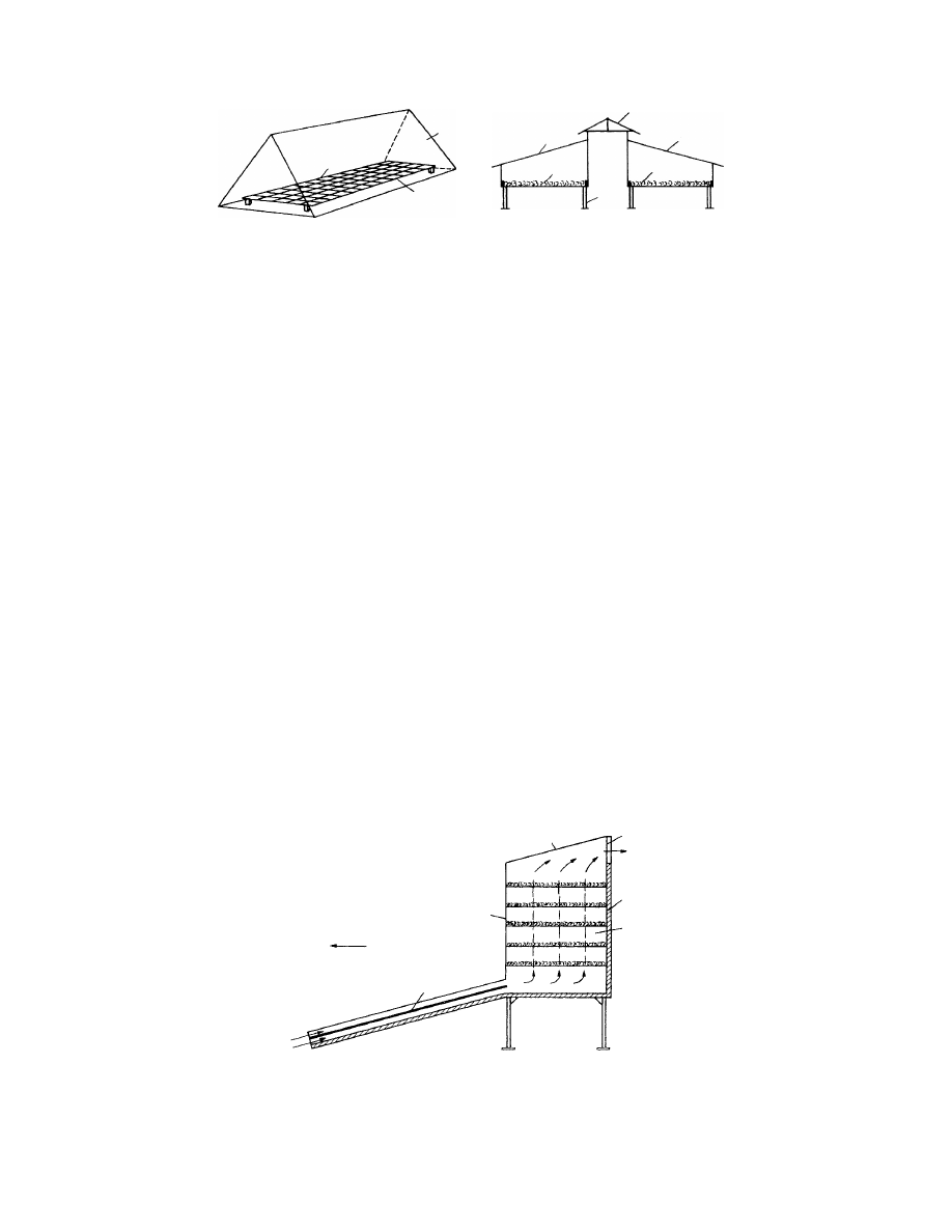
Figure 13.6 shows the schema tic structure of a solar
timber drye r [8,9]. A stack with air clearan ces 1 is
made of 30–65- mm wide conife rous and oa k timb er
in the inner space of a buildi ng. The nor thern wall of
the buildi ng 2 is well insul ated; its roof 3, souther n
wall 4, and sidewal ls are made of specia l two-lay er
transp arent syn thetic plates. The dryer is built on a
concret e base 5. Solar radiat ion co ming in through
the trans parent walls warms the black- painte d alumi -
num absorb er 6. The airflow de livered by an axial
ventilat or 7 flows along the two sides of ab sorber 6;
one part of it enters the stack at the back side, the
other from the bottom. The adjust able angle of in-
clination of the uppe r (top, roof) part of the abso rber
6 makes it pos sible to control the qua ntity of air
directly led into and circulated in the stack. The pr o-
portio n of fres h and recir culated air can be changed
by sim ple flap valves 8. The flow volume of the
ventilat or is 2.5 m
3
/s, with 1 80 Pa. Depending on the
width of the buildi ng, one or severa l ve ntilator s may
be used . (For exampl e, two venti lators are needed for
a 5.64 m wide buildi ng. The he ight of the souther n
wall is 2.50 m; the width of the buildin g is 3.05 m.
Stack volume is 5–9 m
3
. For tests made with a drye r
of sim ilar constru ction, see Ref s. [10,11]; wi th rock
heat stora ge placed on the floor, see Ref. [12].)
The applic ation of forced airflow is necessa ry for
drying pr oducts in static beds, whi ch form a c ompara-
tively large flow resi stance in the bed. Suc h prod ucts
include grains an d hay. One solution is to build a solar
room dryer [13] as sho wn in
. The grains
to be dr ied are placed as a be d 1 on a pe rforated
flooring. Collect ors 2 are locat ed on the souther n
wall and the roof of the buildi ng. The air warmed in
the collectors is ke pt in circul ation through chann el 3
by fan 4 and venti lated through the bed across the
lower distribut ing sp ace 5. Wet air exits to the open
air from the roof space throu gh sidewal l open ings. The
collector area was ch osen to be 4 m
2
for 1 m
3
wheat of
20–24% initial mois ture content (double co vering, 200
W/m
2
long-t erm mean collector power ). M easure-
ments sho wed that a maximum of 55 8 C enteri ng air
tempe rature could be reached withou t influencing ger-
mination ability. In the low er layer s there is the
possibili ty of overdryi ng, which may be avoided
economic ally by employ ing sep arate heat stora ge.
The role of the dryer hous ing ca n be played by a
grain bin [8,14]. In this case the collectors are inte-
grated with the wall of the cylind rical- or squ are-
shaped bin. Othe r varia tions use a separate plane
collector system [15].
Figu re 13.7b shows the schema tic constr uction of
a solar rough fodder dryer [16]. The material is placed
in a static bed 1. The collector system 2 is placed, as in
3
6
7
8
2
8
1
4
6
5
South
FIGURE 13.6 Forced convection solar dryer for timber.
(From Re´sume´ de l’e´tude en cours on CTB sur l’utilization
de l’e´nergie solaire, Centre Technique du Bois, Paris, 1978;
Yang, K.C., Forest Product J., 30, 37, 1980.)
ß
2006 by Taylor & Francis Group, LLC.

Figure 13.7a, on the souther n wall and the roof, but
with airflow in the opposit e direction. The colle cting
channe l is placed at the bottom , joined to the hous ing
of a fan 3. The fan is able to dr aw in outsid e air
directly 4. For bad weat her there is the possibili ty of
using an aux iliary energy source (e.g., gas-he ated he at
exchanger) on the suction side of the ven tilator . (Fo r
further ap plications of collec tors integ rated into the
roof, see Refs. [17, 18].)
13.3.4 .2 So lar Dryers with Phy sical Heat Storage
The application of heat storag e in solar drying syste m
is justified by three circumsta nces:
1. Drying period can be extended by the stored
energy
2. The surp lus energy appea ring at the radiation
peaks can be store d to avoid local overdryi ng
3. The tempe rature of the drying air can be con -
trolled to avoid damage to material
In an y ca se, when dimens ioning the co llector sur-
face of the dryer wi th heat stora ge, attention must be
paid to the fact that the energy ge tting into the stor-
age unit form s a part of the energy gained by the
collector syste m. Also, use of heat stora ge will neces-
sarily involve a decreas e in the tempe ratur e level of
the energy obtaine d. In the case of directly radiated
heat stora ge (formed, e.g. , as the absorber of the
collector) this effect is less impor tant.
One pays for the advantag e of using heat storage
with higher invest ment an d operatin g co sts. Car eful
technoecon omic eva luation must be made be fore
using so lar energy storage in solar drying.
Natur al or artificial mate rials may be employ ed
for heat stora ge. Natural mate rials (wa ter, pebb le
bed, and rock bed) are usu ally cheap er than synthet ic
material s (e.g., latent he at-storing salt solut ions and
adsorbents). Detailed discussion of heat stores is be-
yond the scope of this chapter.
Sensible heat storage of high capacity calls for
water as the working medium (indirect heating sys-
tem). Accordingly, the collectors are more expensive,
and the application of a water–air heat exchanger also
involv es furt her co st (
In Figure 13.8 the construction of a solar dryer
with water storage is shown [19]. The dryer is an
indirect system. Pump 2 circulates the working med-
ium of the collectors 1 along a pipe 3 and warms the
fluid in a storage tank 4. The dryer uses outside air
South
South
2
1
2
3
4
5
2
1
3
(b)
2
Air
in
Air
in
Air
in4
(a)
FIGURE 13.7 Solar room dryers: (a) room solar grain
dryer. (From Wieneke, W., Agricultural Mechanization in
Asia, Autumn, 11, 1980.) (b) Solar fodder dryer. (From
Dernedde, W. and Peters, H., Landtechnik, 29, 1978.)
1
3
2
3
4
6
Air in
Air
out
5
7
8
9
FIGURE 13.8 Solar dryer equipped with water-type heat storage. (From Auer, W.W., in Drying ’80 (A.S. Mujumdar, Ed.),
Hemisphere, New York, 1980, p. 292.)
ß
2006 by Taylor & Francis Group, LLC.
drawn by venti lator 7 and heat ex changer 5. The
primary medium of the heat exchanger is the fluid
from tank 4 circulated by pump 6. Air can be warmed
to the ne cessary tempe ratur e by the he ater 8. The
material to be dried is placed in a static bed 9 . Meas-
urement s have proved that 50–60% of the energy
needed for drying ca n be gained from solar energy.
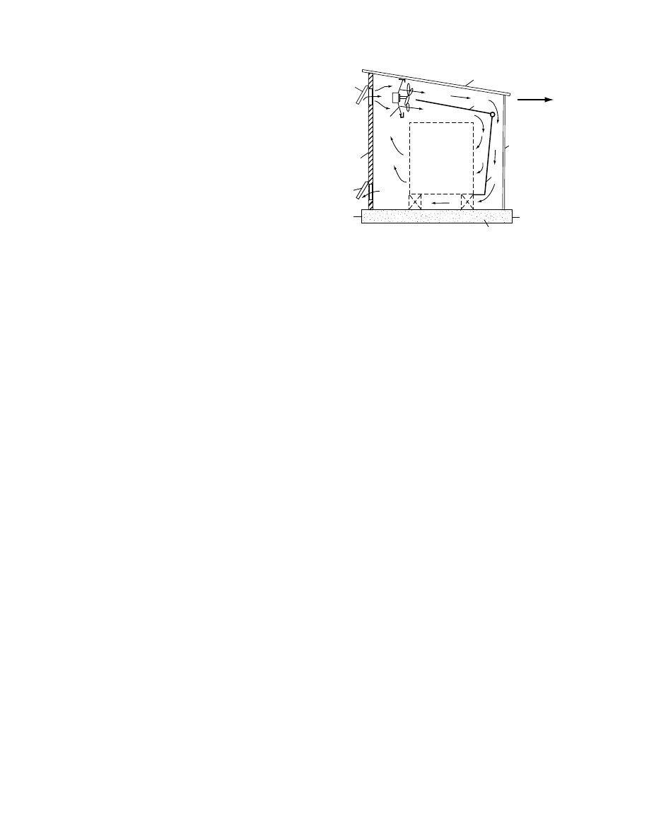
Fig ure 13.9 shows the arrange ment of a solar
dryer with rock-bed storage [20]. The dryer is a direct
system; the colle ctors 1 are located on the grou nd and
have an area of 193 m
2
. The air war med in the col-
lectors is forwarded into drying space 3 by a fan 2.
The dryer has room for a maximu m of 6.5 m
3
timb er
4. In the uppe r roof space two ven tilator s are placed
that are used for c ontinuous circulati on of the air.
Vents 6 are placed in the sidew alls of the roof space
for allow ing inflow and outflo w of air. The rock bed
7 is ab out 22 tons of 19-mm crushed basalt. The dr yer
operate s as follo ws.
1. During the warming period, a fan 2 revolves, first
slowly, then at full rotation; a damper 8 opens
gradually; damper 9 is in the position marked in
the figure by the dotted line. Air flows from the
dryer space back into the collector.
2. During drying a nd ch arging of he at stora ge,
damper 9 is in the pos ition shown in the figu re
by a solid line, air flows from the dryer space
into the rock bed and back to the c ollector.
3. During ope ration when there is no solar radi-
ation, damper 9 is in the medium pos ition, air
flows from the dryer into the rock bed , is
warmed, and flows again into the dryer. The
operation of dampers 6 is con trolled by the wet
bulb temperatur e measur ed in the dryer.
The economic design of the ro ck-bed storage
device is of great impor tance [213] .
13.3.5 S
OLAR
-A
SSISTED
A
RTIFICIAL
D
RYERS
13.3.5 .1 So lar-Assist ed Dryer for Seeds
the scheme of a so lar-assist ed seed
dryer is present ed. Figu re 13.10a sho ws the cross-
section of the dryer with layer -type arrange ment and
Figure 13.10b a co ntainerized constru ction for sensi -
tive mate rials [185, 197,19 9]. The drying space is div-
ided into two c ells 1, 2 for the bette r direct ion of the
drying process (
). Eac h cell ha s
an individu al fan 5 of two RPM stage s. Fans are
arrange d in separate spaces 3. Among the two -fan
spaces the space 4 of the auxiliary heater 6 ope rating
with natural gas is situated (Figur e 13.10c ).
As solar energy convert ers, unc overed flat-pl ate
air c ollectors 7 are used integ rated into the roof struc -
ture of the buildi ng. Air duc ts of the collector field a re
connected to a co llecting– distribut ing air channel 10.
By moving sli ding plate s 11 the co llecting cha nnel can
be ope ned an d conn ected to the fan spaces to divide
the total preheat ed airflow, in a pr oper ratio, between
the cells. For seed grains of small dimens ions a layer -
type static bed is prefer red (Figur e 13.10a ). For seed
grains of large r dimens ions (e.g ., beans) use of co n-
tainers with perfor ated bottom s is recomm ended to
avoid the possibl e da mages during trans portation and
feedin g in and out . M oist air leaves the drying cell s
through the openings 20.
The main techn ical da ta of the dryer are a s
follows :
Number of cells: 2
Effect ive surface area of the bed for one ce ll: 56 m
2
Dry mass of seed for one ce ll and seed grains of
meadow grass: 5,600 kg
M ass flow rate of air of one fan: at RPM 1,090 pe r
min, 41,000 m
3
/h; at RPM 475 per min, 12,500
m
3
/h
Sur face of the co llector fie ld: 191 m
2
Aver age effecti veness of the collector: 0.3
Aver age tempe rature increa se of the air prehea ted
by solar energy (July , Hungary ): at RPM 1090
per min, 2.9 8 C; at RPM 475 per min, 9.86 8 C
Output of the auxil iary air heater : 9 3 kW
(medi um-scale crop-dr yer with ung lazed colle ctor
is present ed in Ref. [218]).
13.3.5 .2 So lar-Assist ed Dryer with Gravel-B ed
Heat Storag e
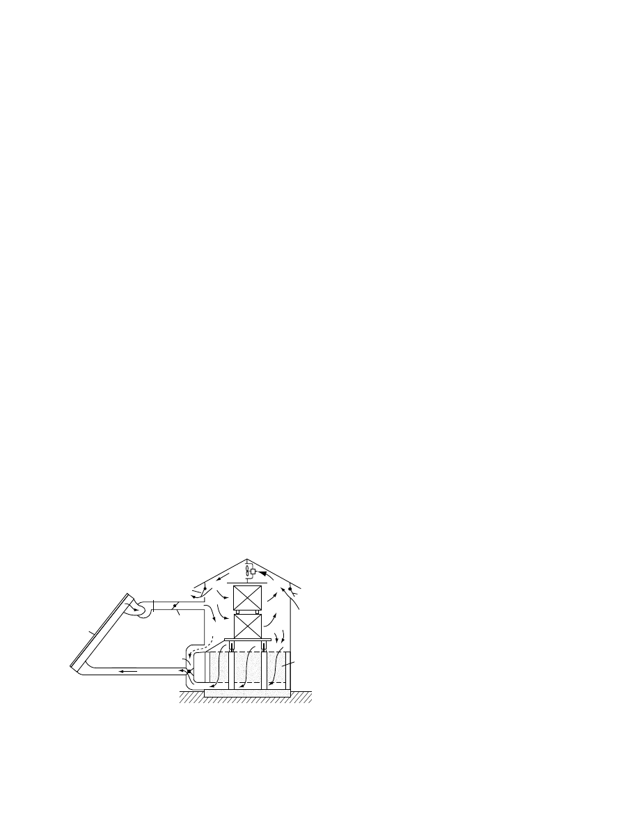
The con struction of a high-pe rformance rais in dry er
is shown in
[19] with rock -bed he at
storage. The collector syst em 1 consists of 42.7-m
long units with a surface area of 1812 m
2
, located on
1
2
6
5
3
4
4
7
6
8
9
FIGURE 13.9 Solar timber dryer equipped with rock-bed
heat storage. (From W. Read, R., Choda, A., and Cooper,
P.I., Solar Energy, 15, 309, 1974.)
ß
2006 by Taylor & Francis Group, LLC.

8
7
9
20
Air in
15
11
3
16
14
2
10
6
5
Air
in
20
21
III
III
II
3
5
17
6
4
13
1
2
13
5
3
17
II
18
18
(a)
(b)
(c)
FIGURE 13.10 Solar-assisted dryer for seeds: (a) cross-section of the dryer in layer-type arrangement; (b) containerized
construction; (c) ground plan of the dryer.
1
11
3
8
6
2
4
5
10
Air
in
7
9
FIGURE 13.11 Solar raisin dryer with gravel-bed heat storage. (From Auer, W.W., in Drying ’80 (A.S. Mujumdar, Ed.),
Hemisphere, New York, 1980, p. 292.)
ß
2006 by Taylor & Francis Group, LLC.
the ground. Fresh air is drawn into the system through
a heat recovery wheel 9 by ventilator 10, and with the
damper 4 in the horizontal position it is sent to the
collector. Air coming from the collectors through
the collecting duct 11 arrives in space 6, where a gas
burner heats it as needed. Ventilator 7 sends the warm
air into a drying tunnel 8 and from there through the
heat recovery wheel into the open air. When switching
on ventilator 2 a part of the air flows through the rock
pile storage 3. If the collector system is out of oper-
ation, air can be circulated into the drying space
through the heat storage with damper 4 in the perpen-
dicular position. Further, if damper 5 closes the upper
duct, the dryer can operate with auxiliary energy as the
only energy source. The solar energy system covers
69% of the energy needed for drying in a yearly 214-d
sunny season in California. (For a similar solution for
crop dehydration, see Ref. [21].)
13.3.5.3 Solar-Assisted Dryer Combined with
Heat Pump and Heat Storage
Heat pumps are coolers (refrigerators) that raise the
energy gained by cooling from a low-temperature
energy carrier with the aid of further external (driv-
ing) energy to a higher temperature level and transfers
it from there to an energy-carrying medium [22,23].
The term heat pump refers to the fact that both the
cooling and the heating performance of the refriger-
ator are utilized.
Figure 13.12 shows the schematic arrangement of
a solar dryer equipped with absorption heat pump
and heat storage [19]. A part of the enthalpy of enter-
ing outside air1 is used—interposing pump system
2—for evaporating sprayed water in an evaporator
3. The water vapor goes over to the brine sprayed into
tank 4. Pump 5 feeds the brine through a regenerator
heat exchanger 6 into a high-pressure boiler 7. Water
in the boiler is distilled with the help of solar energy
obtained in a collector 10 and stored in a water tank
11, and by using auxiliary energy A to the extent
necessary the strong solution is led back into tank 4
through regenerator 6. The high-pressure water vapor
condenses in condenser 8 and with the help of the
pump heat exchanger system 9 warms the air of re-
duced moisture content, which is supplied to the
dryer. The condensed high-pressure water flowing
through an expansion valve E cools and arrives in
evaporator 3. This system was originally designed
for drying peanuts. A ‘‘hybrid’’ solar dryer with heat
pump and photovoltaic modules has been constructed
for drying vice [219].
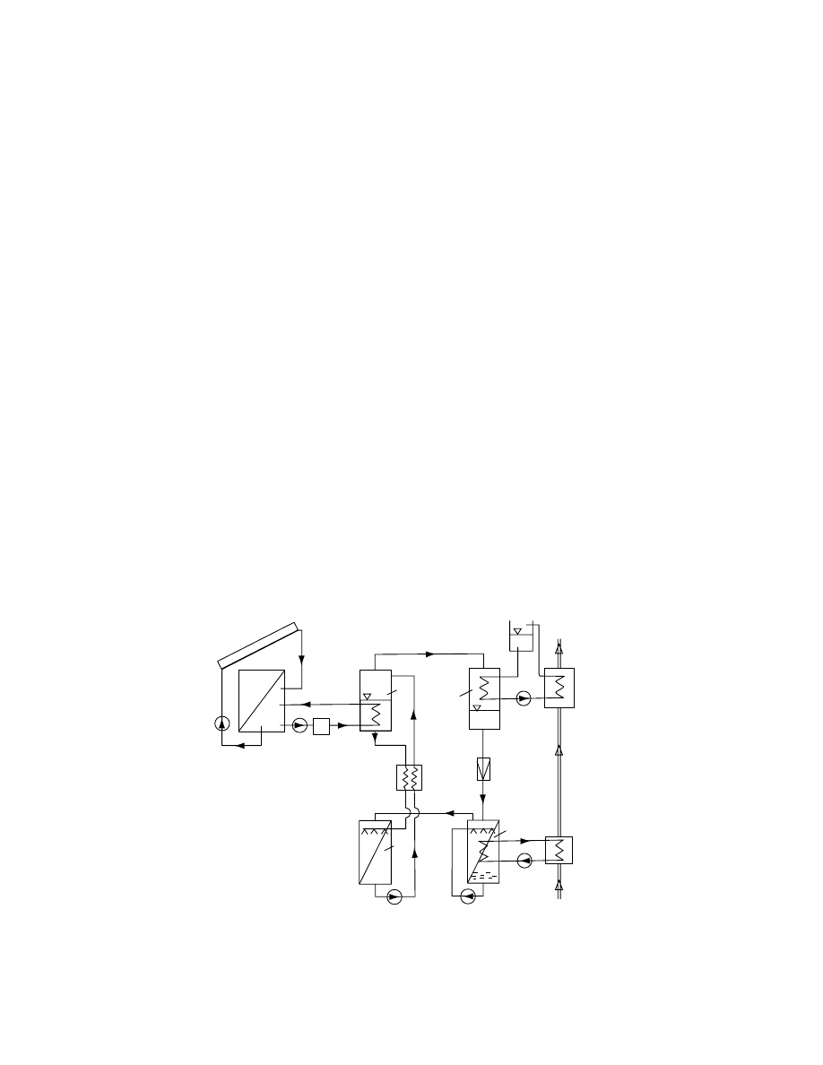
13.3.5.4 Solar-Assisted Dryer Integrated
into a Complex Energy System
One economic factor in the use of solar dryers is the
amount of solar energy over the year and the yearly
drying period. In any case, even in the drying season
there are unavoidable breaks, and during the rest
of the year the collector system cannot be used for
10
11
A
7
8
6
4
5
P
2
9
To
dryer
E
Air in
1
3
FIGURE 13.12 Solar dryer for peanuts equipped with absorption heat pump and heat storage. (From Auer, W.W., in Drying
’80 (A.S. Mujumdar, Ed.), Hemisphere, New York, 1980, p. 292.)
ß
2006 by Taylor & Francis Group, LLC.
utilizin g solar energy. For year- round utilizat ion it is
desirab le to look for other possibi lities for using solar
heat. Such a possibili ty is given, for inst ance, by
satisfy ing the hot water needs of a stock- breeding
farm. With the integ ration of the so lar syst em into
the hot water system of the farm , investmen t costs can
be saved . The storage tank of the hot wat er syste m
can be used a s wat er stora ge for the solar syst em. In
additio n, the complex system solut ion may permi t
increa sing the effici ency of the solar system and thu s
the amoun t of solar energy obtaina ble. The efficiency
of fla t-plate co llectors (for more detai ls
) impr oves with decreas e in operati onal tem-
peratur e. So it is more advan tageous if the colle ctors
are used for war ming cold water from wells or the
water supply system than if the workin g medium
return ing from the fluid–ai r he at exch anger of the
dryer is led into the co llector at a tempe rature high er
than the ambie nt.
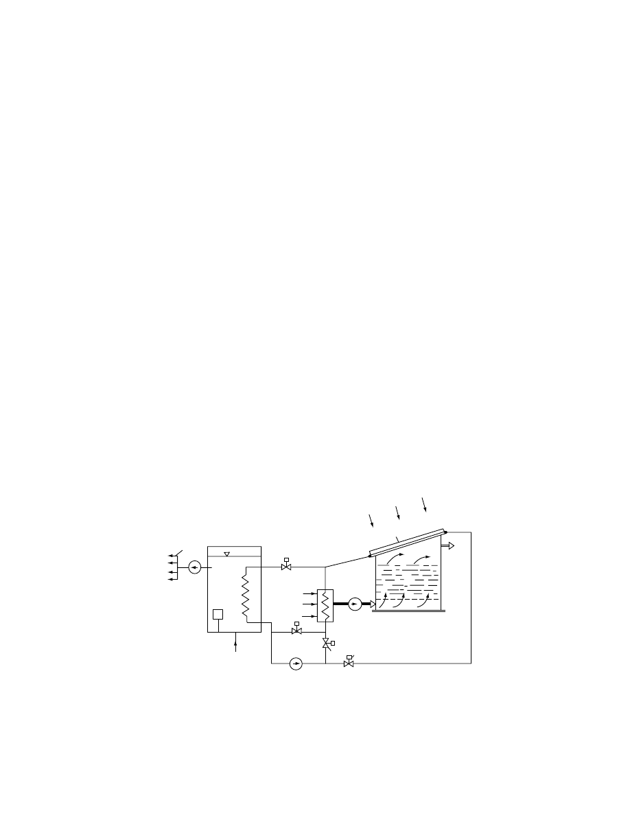
Figu re 13.13 sho ws the scheme of a solar alfalfa
dryer joined to the hot wat er syst em of a stock-
breeding farm [24,25,19 9]. The flui d med ium colle ctor
system 5 built on top of the dryer buildin g is co n-
nected to a closed circui t. The system can have differ-
ent ope rating mo des. When valves 2 and 3 are closed,
the colle ctor system works on the fluid –air he at ex-
changer 6 and serves dryer 7. With valves 1 and 3
closed, the water heat storage 8 is warmed. In the
transiti on pos ition of valves 1 and 2 (val ve 3 is closed) ,
the two mo des can parti ally ope rate sim ultane ously.
If valves 1 an d 4 are closed, the drying air is warmed
in heat exchang er 6 by using the hot water reser ves of
heat stora ge 8.
The air leavi ng the dryer has almos t the same
enthal py it ha d on enteri ng the dryer. A co nsiderab le
part of the enthalp y used on drying can be regai ned
by co ndensing the ab sorbed wat er vapor. For this
purpose a heat pump may be inserted in the energy
system.
ill ustrates the sch eme of a syste m
complete with a he at pump [24]. Part of the mois t air
leaving the dryer flows through the evapo rating he at
exchanger 9 of the heat pum p, and a pro portion al
part of its mois ture co ntent is condensed . The he at
input to the worki ng medium of the heat pum p (com-
pleme nted by the input en ergy of compres sor 10 and
with the aid of the con denser he at exchanger 11) can
be taken into the hot water syst em. Depen ding on the
ambie nt state, the air leaving heat exchanger 9 can be
return ed to he at exchanger 6 of the dryer. (Other
labels in the figure are the same as those in Figure
13.13.) In the case of a drye r c onnected to the energy
system of a cattle- raising farm , a heat pum p can be
also us ed for co oling mil k and prod ucing hot water at
the same time.
Inasm uch as the stock- breeding farm possess es a
biogas-p roducing system, the hot wat er pro duced can
be utilized for heatin g the gas-pr oducing co ntaine rs in
place of biogas, whi ch c an be util ized in other ways .
In this case, naturally, biogas can be used as an
auxiliary en ergy source for the dryer during pe riods
of ba d weather.
When solar dryers are integrated into the complex
energy system of a farm, adsorbent beds can also be
utilized as auxiliary units. Adsorbent materials have
to be regenerated for exploiting their dynamic ad-
sorption capacities. The regeneration temperature is
5
9
8
2
6
7
3
4
Fan
Cold water
in
Pump (1)
A
Pump
(2)
Air
in
Air
out
1
FIGURE 13.13 Solar hay dryer connected to technological hot water system of stock-breeding farm. (From Imre, L., Kiss,
L.I., and Molna´r, K., in Proceedings of the Third International Drying Symposium (J.C. Ashworth, Ed.), Drying Research
Limited, Wolverhampton, England, 1982, p. 370; Imre, L., Farkas, I., Kiss, L.I., and Molna´r, K., in Third International
Conference on Numerical Methods in Thermal Problems, Seattle, 1983.)
ß
2006 by Taylor & Francis Group, LLC.
typicall y ov er 150 8 C, depending on the adsorb ent
[26]. A con dition of economic al ap plication is that a
consider able pa rt of the energy use d for regener ation
should be us ed for producing hot wat er, for exampl e.
Durin g breaks in solar radiation , drying can be co n-
tinued at the expense of the ad sorption capacit y of the
adsorbent s. Ther efore, the ad vantage of applyi ng ad-
sorbent s is that a consider able part of the energy used
for regen erating the adsorbent can be util ized mo re
cheaply for other purpo ses than using the same en-
ergy for heati ng the drying air.
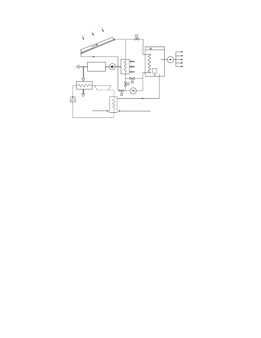
13.3.5 .5 S olar-Assist ed Adso rption Dryer
shows the scheme of a complex solar
system co mplemen ted with ad sorbent units [24]. Air
warmed in the air-type co llector system is delivered to
the dryer by fan 1. The ducts of the adsorben t units
are joined to the duct section before the fan at points
2 and 3. Un it A2 in the state dr awn in the figure (thick
lines) is unde r regener ation; active unit A1 is unde r-
going ad sorption . At joint 3 dry air flows to the
airflow of fan 1. Fan 2 draw s air through filter F;
then the airflow is divide d into tw o parts . In the open
position of 8 an d closed pos ition of 9 a pa rt of the
airflow goes through A1 to the sucti on side of fan 1;
the other part is war med in heat e xchanger H1 and
serves the purpo se of regener ating unit A2 and then
moving into heat exch anger H2. The primary medium
of heat exch anger H1 is air heated by energy sou rce
E (e.g., biogas) , and driven by fan 3. The medium
leaving heat exchangers H1 and A2 flows into the
second pa rt of heat exchanger H2. Heat exchang er
H2 is con nected to the water system of tank T of the
hot wat er syst em. Water is circulated by pum p 1.
Pump 2 supp lies hot water for 15 consumer lines .
(A is the auxiliary energy source of the water tank.)
The energy co nditions of solar dr yers integ rated
into a co mplex energy system are favora ble. At the
same tim e, the number of necessa ry au xiliary eq uip-
ment is greater, investment costs are higher, and co n-
trol of the syst em is more co mplicated. The eco nomics
of such a system dep end on local conditi ons.
Solar dryers can be used with an adso rption bed
for energy stora ge [12,26–29] . The stora ge of energy
accordi ngly occurs, partly in the form of physica l he at
and partly in the form of mois ture adsorpt ion cap -
acity. The total energy storage capacit y of the ad sorb-
ent heat store per uni t mass is abou t ten time s great er
than that of a physical heat store. An optimally
designed timber dryer fitted with adsorbent energy
storage has been compared with rock-bed storage
and proven competitive [28,29].
13.4 ECONOMICS OF SOLAR DRYERS
13.4.1 M
AIN
E
CONOMIC
F
ACTORS
The economics of solar drying depend on the costs
involved and benefits gained. Interpretation of the
benefits gained by solar dryers is less unambiguous
than that of other solar systems [196]. The main
5
2
6
8
4
11
10
3
1
9
Pump (2)
Pump (1)
A
Dryer
Fan
7
9
12
Cold
water
Cold water
in
Air
out
FIGURE 13.14 Complex solar dryer system combined with heat pump. (From Imre, L., Kiss, L.I., and Molna´r, K., in
Proceedings of the Third International Drying Symposium (J.C. Ashworth, Ed.), Drying Research Limited, Wolverhampton,
England, 1982, p. 370.)
ß
2006 by Taylor & Francis Group, LLC.

reason can be found in the great variety of solar
dryers. For evaluation of the gain a correct basis
should be interpreted by finding the extra income
(i.e., the savings) of the solar dryers as compared to
a basic solution [175,176].
Natural solar dryers should be compared to open-
air drying. Savings are realized by reducing the losses
of the open-air drying and no energy savings can be
considered. Semiartificial solar dryers should be com-
pared to an artificial dryer with the same perform-
ance. Their advantages are in reducing the first costs
by an unsophisticated construction and by the energy
substituted by solar energy. With solar-assisted artifi-
cial dryers, savings should be interpreted by the sub-
stituted energy. As costs, the investment of the solar
energy converting system should be taken into ac-
count only.
The savings depend on the lifetime of the dryer
and, for the last two main groups of solar dryers, on
the cost of the substituted fuel or energy carrier. The
lifetime of the dryer can be estimated in advance; it is
in any case related to the maintenance costs as well.
An error made in the estimation of lifetime may cause
significant uncertainty in the economic evaluation.
The price of the dried products and the substi-
tuted energy is not stable. These prices may change
during the lifetime of any dryer. For changes in the
prices, predictions can be used; however, these must
be taken as estimates, again causing some further
uncertainty in economy calculations.
The sum of overall installation costs is composed
of investment costs, interest and maintenance, service,
tax, and insurance charges. Inflation modifies the
total cost of installation. In view of the uncertainties
mentioned it is expedient to make some estimations
for the calculations.
13.4.2 D
YNAMIC
M
ETHOD OF
E
CONOMIC
E
VALUATION
Economic evaluation of solar dryers usually aims at
determining the payback time. The dynamic method
of calculations takes the influence of inflation into
consideration. The following considerations summar-
ize this method, according to Bo¨er [30].
Payback occurs when the accumulated savings S
equals the sum of investment capital I plus yearly
interest and the accumulated costs E:
Air in
1
2
5
4
A1
E
H1
A2
3
6
8
11
9
10
12
T
A
15
14
13
H2
Fan 1
Fan 3
Fan 2
Pump 1
Pump 2
Pump 3
Cold water
in
F
Air out
Dryer
7
FIGURE 13.15 Arrangement of solar-assisted dryer combined with adsorbent units. (From Imre, L., Kiss, L.I., and Molna´r,
K., in Proceedings of the Third International Drying Symposium (J.C. Ashworth, Ed.), Drying Research Limited, Wolver-
hampton, England, 1982, p. 370.)
ß
2006 by Taylor & Francis Group, LLC.
S
¼ I þ E
(13:1)
The annual accumulated savings can be calculated
from the net income D by reducing the mass and
quality losses and thus by increasing the marketing
price of the product in case of natural solar dryers.
For semiartificial and solar-assisted artificial dryers
savings can be calculated from the price of the sub-
stituted conventional energy D. Considering the an-
nual interest rate r and the yearly inflation rate e for
the prices of energy, for n years the annual accumu-
lated savings can be calculated as follows:
S
¼
(1
þ r)
00
(1 þ e)
00
r
e
D
(13:2)
The sum of first investment cost C with interest will
be, during n years,
I
¼ C(1 þ r)
00
(13:3)
Accumulated yearly costs, taking the annual fixed
charge rate mC and inflation rate i for equipment
into consideration, will be
E
¼
mC(1
þ r)
00
mC(1 þ i)
00
r
i
(13:4)
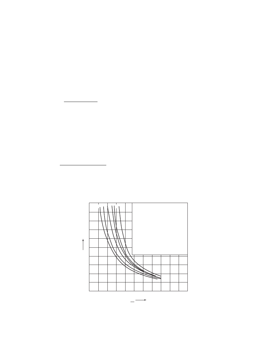
Knowing C and D, diagrams can be made for the
determination of payback time n, referring to values
of r, m, i, and e. From these diagrams the require-
ments for the expected payback time can be easily
seen. Figure 13.16 shows the payback time as a func-
tion of D/C for various values of r, m, i, and e,
following Bo¨er [30]. One can see from the diagram
which D/C values can bring about the desired pay-
back time when the various other parameters are at
given values. With parameters differing from the
above, the calculation must be made separately fol-
lowing Equation 13.1 through Equation 13.4. A com-
parison of curves 1 and 2 indicates the influence of
interest rate r in cases with no inflation; curves 3 and
6, when compared, lead to the effect of energy prices.
As can be seen in all the cases examined, the D/C ratio
needed for a 10-year payback time falls in the 0.12–
0.23 range. Since payback time is a function of D/C, it
is obvious that cheaper (smaller C) and less efficient
(smaller D) installations are justified insofar as real-
ization of less expense does not mean a significant
decrease in the durability (lifetime) of the system.
Payback calculations refer to the whole solar en-
ergy drying system [31,32]. With appropriate division
of the costs, there is of course nothing in the way of
making the calculation only for the collector system
[33,34]. Construction of the collectors can be planned
on the basis of the economic optimum [35,36].
When the application of a solar dryer results in
improved quality of the dried product, the value of
D is savings S and has to be increased in relation to
the value of the quality enhancement.
0.1
2
4
6
8
10
12
14
16
18
20
0.2
0.3
0.4
1:
r = 0.1
m = 0.05
i = e = 0
2:
r = 0.055
m = 0.05
i = e = 0
3:
r = 0.065
m = 0.05
i = 0.05
e = 0.04
4:
r = 0.1
m = 0.05
i = 0.05
e = 0.09
5:
r = 0.0055
m = 0.05
i = 0.05
e = 0.09
6:
r = 0.0065
m = 0.02
i = 0.05
e = 0.09
6
2 1
5 4 3
D
C
n
years
FIGURE 13.16 Payback time in years as a function of D/C, with different parameters r, m, i, and e. (From Bo¨er, K.W., Solar
Energy, 20, 225, 1978.)
ß
2006 by Taylor & Francis Group, LLC.

13.5 KEY ELEMENTS OF SOLAR DRYERS
13.5.1 S
OLAR
C
OLLECTORS
13.5.1 .1 Cons truct ion of Solar Collectors
The solar colle ctor plays the part of primary ene rgy
source for a so lar dryer. Essentiall y it has functio ns of
energy con version and energy trans fer. As energy co n-
verter the collector convert s the direct and diffu se
radiation coming from the sun into heat. Thi s energy
transform ation takes place in the so-called absorber of
the co llector (Figur e 13.17). The absorber is made of a
material of high a bsorption coefficien t for the radi-
ation of the sun or has a coati ng with su ch a charact er.
The radiat ion abso rbed ca uses the inner energy of the
absorber to grow an d its tempe rature to rise .
The energy- trans ferring functi on is to trans fer the
radiation energy trans formed into heat in the ab -
sorber to the workin g medium of the collector. The
workin g medium is, wi th direct syst em solar dryers ,
the drying air itself; wi th indir ect systems this is an
approp riately cho sen liqui d (dis tilled wat er or, in
winter ope ration, a fluid with low freez ing point, oil,
and nona queous liquid s).
Heat trans fer betw een absorber and the medium
flowin g through the collector occu rs by co nvectio n.
Only pa rt of the heat coming from the incide nt radi-
ation gets into the workin g medium .
The part of the radiant energy irradiat ed that
causes in increa se of enthalp y of the working medium
flowin g through the colle ctor is consider ed utilized
heat; the rest is heat loss. For atta ining a realist ic
rate of heat loss mo st colle ctors are covered with
transp arent material s to solar rad iation (gla ss, plast ic
foil, and others ). If the absorpt ion of the cove ring
material and its refl ection is high for the absorber ’s
own long-w ave radiat ion, it will reduce the radiation
loss of the absorber . For reducing the radiation loss, a
coatin g that selec tive ly reflect s long-w ave radiation
can also be app lied to the coveri ng. Since the tem-
peratur e of the coveri ng is con siderab ly low er than
that of the absorber , the coati ng will also reduce the
convecti ve he at loss from the struc ture to the ambie nt
air. The number of co verings is usuall y not more than
two. For the redu ction of furt her heat loss it is desir -
able to insulate the nontrans paren t pa rts of the col-
lectors. Effi cient means for redu cing convec tive he at
loss are co llectors with the space between cov ering
and a bsorber evacuat ed (vacuum colle ctors); this
makes the colle ctors expen sive.
The final form of the colle ctor is a problem of
reading a technoeco nomic optim um (see for instan ce,
the D /C ratio in
). In general , beyon d a
certain limit the reducti on of heat loss is no longe r
economic al.
The simp lest types of solar dryers (e.g ., cab inet
dryers , tent dryers , and certain chimney shelf dryers )
(
), do not
employ a separate absorbe r; the role of the absorber is
played by the irra diated mate rial its elf. The major ity
of high-pe rforman ce solar dry ers are eq uipped with
flat-plate collectors [205].
presen ts flat-plate co llectors withou t
coveri ng using air as the worki ng medium . Air flows
in the ch annel betw een the absorber and the he at
insulati on. The absorb er is a co mmercial ly avail able,
rolled meta l shee t, usually with a surfa ce coating.
Absor bers made of zinc or steel galvanized with zinc
can be applie d without a co ating. The applic ation of
collectors without a coveri ng is just ified for low -per-
forman ce dry ers.
shows some variations of air-type
collectors wi th one coverin g. These struc tures can
also be made with two coveri ngs. Flow under the
absorber reduces the con vective heat loss of the air
from the covering. There are designs in which air
⫻
⫻
⫻
1
(a)
(b)
1
2
2
3
1
2
3
FIGURE 13.17 Setup of flat-plate collectors: (a) air; (b) liquid as working medium (1, covering; 2, absorber; 3, heat
insulation).
ß
2006 by Taylor & Francis Group, LLC.
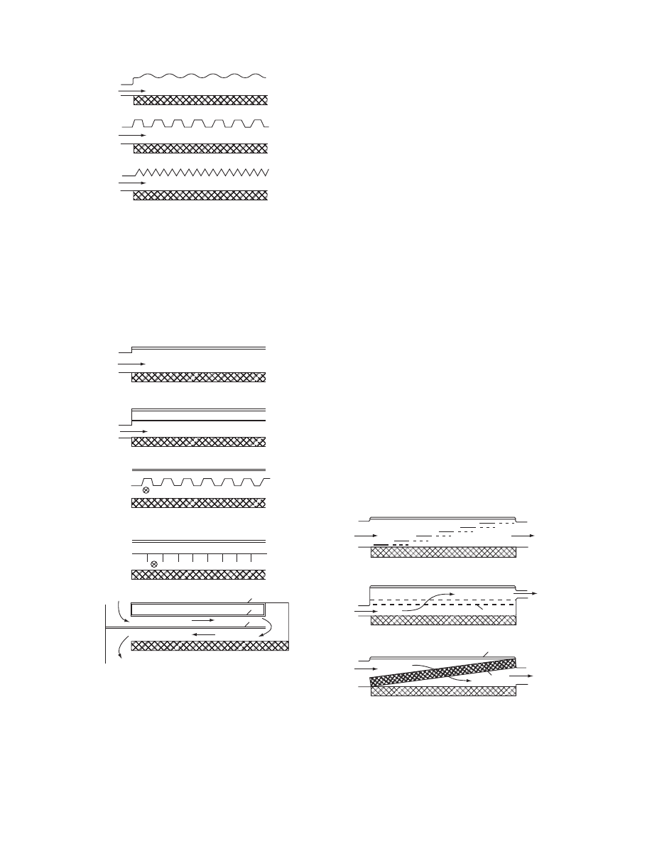
flows on both sides of the ab sorber. A c orrugated or
finned absorber surfac e impr oves heat trans fer be -
tween air and absorber . With the latt er, flow direction
is usuall y parallel to the fins.
Improv emen t of heat trans fer betw een air and
absorber is aime d at collector de signs with ab sorbers
of divided surface (Figure 13.20). The air is forced to
flow through the gaps. There are a large number of
matrix-type and porous absorbers. The matrix-type
absorber, for instance, can be made of wire bundles
and of slit and expanded aluminum foil (Figure
13.20c).
An air collector with integrated latent heat storage
. The casing
of the heat storage material acts as the absorber [37].
Here advantage over air-warmed storage is that heat
store warms through direct irradiation; thus heat-
storing materials having a phase-change temperature
[38,39] higher than the temperature of the air can be
used. An integrated rock absorption and storage air
collector system has also been developed [40].
Another variation of combined collectors is the hy-
brid (two-working media) collector (Figure 13.21b).
Hybrid collectors are liquid-type collectors in which
air flows over an absorber that is common for air
and liquid. The application of hybrid collectors is
reasonable if the dryer is connected with sensible heat
water storage [25]. During collection, hybrid col-
lectors warm air and water simultaneously, the latter
serving to charge the heat storage tank. During the
radiation-free period of operation (e.g., night), the hy-
brid collector works as a water–air heat exchanger
and, using hot water from the heat storage tank, pre-
heats the drying air. Both integrated collector types
can operate at night as they are usually made with a
(a)
(b)
(c)
3
2
3
2
3
2
FIGURE 13.18 Scheme of flat-plate collectors without cov-
ering, with air as working medium: (a) corrugated plate; (b)
trapezoid plate; (c) triangle waved plate (as absorber).
(a)
(b)
(c)
(d)
(e)
3
2
3
2
3
2
3
3
2
2
1
1
1
1
1
1
FIGURE 13.19 Scheme of air-type flat-plate collectors with
covering: (a) plane absorber, flow over absorber; (b) plane
absorber, flow under absorber; (c) absorber with corrugated
surface; (d) finned absorber (in c and d, flow is under the ab-
sorber, perpendicular to the plane of the paper); (e) plane
absorber, flow over and under absorber (two way). (From
Vijeysundera, N.E., Ah, L.L., and Tijoe, L.E., Solar Energy,
28, 363, 1982.)
3
3
3
(c)
(b)
(a)
1
1
1
2
2
2
FIGURE 13.20 Air-type flat-plate collector constructed with
divided surface absorber: (a) stepwise divided absorber
made of overlapped plates; (b) perforated double-plane ab-
sorber; (c) matrix-type absorber.
ß
2006 by Taylor & Francis Group, LLC.

double (glass–glass or glass–foil) covering to reduce
radiation loss at night.
A very simp le design of air collectors is the poly-
ethylen e tube colle ctor [41]. A black absorb er tube is
placed insid e a clear tube con nected to the fan. The
tube assum es its cyli ndrical form on overpres sure. It
can be laid on the ground in approp riate length ,
chiefly for agric ultural drying purposes.
Air -type co llectors have the advan tage of cau sing
no serious conseque nces if leakin g occu rs [42]. Dif fi-
culties may arise in unifor m dist ribution of air: for
advantag eou s even dist ribution, con siderab le fan per-
forman ce is needed. This ha s some unfavora ble infl u-
ence on operati ng costs.
Col lectors wi th a liquid worki ng medium are used
for indir ect-type solar dryers , us ually with water heat
storage . Their app lication for high -performanc e in-
stallation s is justified because no large and costly
distribut ing and colle cting air ch annel system is
needed as for the air-type collectors . On the oth er
hand, a water–ai r heat exchanger must be employ ed .
A draw back of the liquid-t ype collectors is the
danger of leakage and freezing. The form er can be
averted by approp riate junction s that permi t dilat a-
tion, the latter by using antifreeze liquid s as working
media , for examp le, by integratio n into the hot wat er
system of the farm for year-ro und perfor mance.
Ow ing to the wi despread app lication of solar hot
water systems, a great number of varia tions of fluid
collectors ha ve been developed an d commer cialized
circulati on. It is most ly the 1–2 m
2
surface-m ounted
units that are avail able commer cially; these, joined in
an ap propria te number, form a full collector syst em.
The advantag e of commer cially avail able colle ctor
surface s is the quick and sim ple replac ement of the
elemen ts and guarant eed therm al effici ency. A disad-
vantage is the usu ally high investmen t cost and the
long payback time . For indir ect solar dryers , low er
cost is involv ed with panel-type collectors , if the costs
of collectors need to be reduced . Pane l collectors can
be used for both air a nd fluid workin g media . The
absorber and he at insul ation form a singl e continuou s
surface, an d it is only the glass coveri ng that is made
of smal ler fram ed parts . If placed on the roof of an
agricu ltural buildin g, the c ollector integ rated in the
roof struc ture can play the role of roofin g as well. The
absorber surface of panel- type colle ctors can be
mounted on 5–10-m long elemen ts corres pondin g to
the full wid th; thus the number of joint s is consider -
ably less than those of surfac es made of smal l col-
lector units . In this way not only the constr uction cost
is lower, but the pr obability of leakage is also re-
duced.
The abso rber of the liquid -type collector most fre-
quently used for solar dryers is a surfa ce formed of
ribbed pipes. Its material is metal or syn thetic (plas tic).
Plastic is used for pro ducing carpet-lik e co llectors co n-
taining ap propria te fluid ducts. The colle ctor carpet
usually bro ught into c irculatio n can be spread ov er a
very large , contigu ous surfa ce and can be used with
panel colle ctors, too, with or without coveri ng. Its
advantag e is sim ple moun ting; its disadva ntage is its
wear. The ultr aviolet (UV)- stabilized constru ction ha s
a comp arativel y long lifespan. Plast ic is also used for
making absorbe rs of pipelines laid side by side [43] .
Their disadva ntage— apart from that alrea dy men -
tioned— is that a great number of connecti ons and
very caref ul moun ting are requir ed. Anothe r disad-
vantage of plastics is their sensi tivity to high tempe ra-
ture. Even on using a cover a tempe rature rise in the
absorber of over 100 8 C may occu r if there is no he at
remova l. The tempe ratur e of colle ctor types without a
coveri ng does not rise to a dan gerous level.
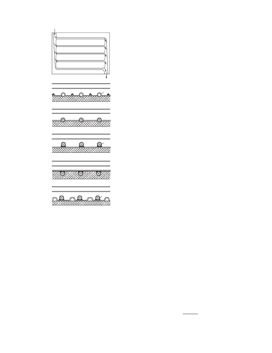
M ost liquid colle ctors used wi th high-pe rform -
ance solar dryers are mad e with a finne d meta l tube
absorber . The absorber s applie d to solar hot wate r
producing systems are often made of sheet ha lves
with stamped passages bonded by seam welding or
by rolling them toget her (
) .
Flat-plate collectors with finned tube absorber
(shown in Figure 13.22b) can be built of extruded
elements. This is proposed for integrated or panel
collectors. The absorber elements perpendicular to
the plane of the paper can be ordered from the manu-
facturer by length of the panel. The structure must be
designed so that dilatational movement of the elem-
ents is possible. Collectors built of absorbers from
pipes soldered or welded to a sheet are shown in
Figure 13.22c through Figure 13.22f. The type in
Figure 13.22f ensures great strength (rigidity) even
with long panel collectors.
The materials commonly used for finned tube ab-
sorbers are copper, aluminum, or steel [44]. Copper is
rather expensive for dryer collectors. Aluminum gives
•
1
1
1
1
Air
Liquid
2A
2
3
(b)
(a)
3
FIGURE 13.21 Integrated collector types: (a) latent heat
storage filling, as absorber (2A); (b) hybrid (air–liquid)
collector.
ß
2006 by Taylor & Francis Group, LLC.
a long operation life with nonaqueous working
media. The corrosion of steel can be reduced with
the application of inhibitors.
13.5.1.2 Efficiency of Flat-Plate Collectors
The surface required for the collectors of solar dryers
can be determined from the energy demand of the
dryer. In most solar dryers, drying takes place in
stages and only a small part of a dryer is used for
drying of continuous material flow.
In the case of drying in stages, the energy de-
mand is not constant: it is greater at the beginning
of the drying process and decreases as drying pro-
ceeds. For dimensioning the collectors, the starting
point must be the drying requirements and thus
the drying characteristics of the material. Drying
requirements specify the planned drying time and
the permissible material temperature, among others.
The drying characteristics of the material serve to
determine, with the help of simulation or laboratory
drying experiments (or both), the necessary inlet
characteristics of drying air (temperature and rela-
tive humidity) and the necessary air mass flow rate
_
m
m
a
for the drying period with the highest energy
demand.
The air is usually taken from the surroundings. In
the case of a direct system, the air collector, and with
an indirect system the liquid-type collector and
liquid–air heat exchanger, serve to heat the air. If
heat storage is also employed, the temperature of
the medium leaving the collector has to be set to
a value that can ensure the prescribed temperature
of the drying air even when air heated by the heat
storage is used.
In the case of drying in continuous material flow
or of preliminary drying, the drying energy demand
for a given material is nearly constant over time. The
standard energy demand of the dryer f
d
is covered by
the enthalpy increase of the drying air. When using a
direct system, the temperature of the air entering the
dryer T
d,in
is equal to the temperature of the air
leaving the collector (T
c,out
¼ T
d,in
). The necessary
enthalpy increase of the air in the collector is
f
¼ _
m
m
a
c
p
,
a
(T
c
,
out
T
c
,
in
)
(13:5a)
With air-type collectors, if recirculation from the
dryer is not employed the temperature of air entering
the collector is equal to the ambient temperature
(T
c,in
¼ T
o
).
With liquid-type collectors, Equation 13.5a is
valid for the air flowing through the fluid–air heat
exchanger (T
c
¼ T
H
). The necessary temperature T
f
’
of the fluid entering the heat exchanger from
the collector (T
f
’
¼ T
c,out
) can be determined by the
efficiency of the heat exchanger H. For _
m
m
a
c
p,a
>
_
m
m
f
c
p,f
the energy balance for adiabatic heat exchanger
gives
f
d
¼ _
m
m
f
c
p
,
f
H(T
0
f
T
o
)
(13:5b)
If the heat loss of the flow duct system f
l
is not
negligible [45], the energy demand for the collector is
f
u
¼ f
d
þ f
l
.
Therefore from Equation 13.5b
T
0
f
¼ T
c
,
out
¼
f
u
_
m
m
f
c
p
,
f
H
þ T
o
(13:5c)
(a)
(b)
(c)
(d)
(e)
(f)
1
1
3
1
1
1
1
3
3
2
1
1
3
1
1
3
2
2
2
2
+
+
+
FIGURE 13.22 Some designs of liquid-type collectors: (a)
absorber plate made of stamped sheets; (b) collector with
extended finned tube absorber elements; (c) through (f)
different tube-sheet, flat-plate collectors.
ß
2006 by Taylor & Francis Group, LLC.

The ne cessary en thalpy increase for the fluid flowing
through the liquid-t ype collector is
f
u
¼ _
m
m
f
c
p
,
f
( T
c
,
out
T
c
,
in
) (13 : 6)
When using air co llectors, the full airflow demand by
the dryer is gen erally led through the co llector (the
value of _
m
m
a,c
will be equ al to the energy de mand of the
dryer, _
m
m
a
). The air heated in the co llector can be
mixed with the air sucked in direct ly from outsi de in
a mixi ng space form ed on the suction side of the fan.
The _
m
m
f
mass flow rate in the colle ctors of indir ect
system dryers can be ch osen, within certain limit s.
Howev er, _
m
m
f
is inter depen dent wi th the thermal effi-
ciency h of the colle ctor. Aft er clearing up the neces-
sary energy flow rate to be utilized in the co llector, the
requir ed c ollector su rface must be determ ined. On the
basis of util ized f
u
heat flow rate and the en ergy flux
of the incide nt radiat ion (energ y flow rate pe r surface
unit: irra diance) , the efficien cy of the colle ctor can be
express ed as
h
¼
f
u
A
c
I
(13 : 7)
where A
c
is the necessa ry co llector surface. Equation
13.7 can be interp reted only as a transient value
owing to the tim e de penden ce of the irradiance.
For a defi nite period, the so-called long-term effi-
ciency of the co llector can be express ed with the time
integral of util ized an d inp ut energy flow rates
h
¼
Ð
t
t
o
f
u
dt
A
c
Ð
t
t
o
I dt
(13 : 8)
The durati on for averagi ng can be chosen in acco rd-
ance with the operatin g time of the co llector and the
purpose of calcul ation (daily, monthl y, or yearly
long-term efficien cy).
The efficie ncy of the colle ctor can be determined
by calcul ation and measur ement s. For design pur -
poses, different calcula tion method s c an be used
[34,35,37 ,46–52 ]. The effici ency data for co mmercial ly
availab le colle ctors are determ ined by standar d meas-
urement s [53, 54]. (For ‘‘s econd law efficie ncy,’’ see
Ref. [55].)
13.5.1 .3 Sim plified Calcul ation
of Colle ctor Efficien cy
In Equat ion 13.7 of the inst antaneous efficiency ,
utilized heat flow rate f
u
is the diff erence be tween
the heat flow rate absorbed by the absorber f
a
and the
heat flow rate lost f
l
to the ambient air
f
u
¼ f
a
f
l
(13:9)
where
f
a
¼ taIA
c
(13:10)
is the heat flow rate absorbed by the absorber from
the irradiation getting through the covering, and
f
l
¼ A
c
U
l
(T
a
T
o
)
(13:11)
is the heat flow rate transferred to the ambient air from
an absorber at T
a
temperature. In Equation 13.11, U
l
is
the overall heat transfer coefficient of the collector to
the a mbient air. Subs tituting into Equation 13.7, the
instantaneous efficiency of the collector is [46–50]
h
¼ ta U
l
T
a
T
o
I
(13:12)
If t, a, and U
l
are taken as constant values, instant-
aneous efficiency in the function
f
¼
T
a
T
o
I
(efficiency function, an independent variable) can be
plotted as shown in Figure 13.23. At a given operat-
ing point, the utilized energy flow rate from the col-
lector is f
u
¼ hA
c
I.
These considerations can be appropriately applied
according to Equation 13.8 for expressing the long-
term efficiency by substituting time averages (I)
av
,
(T
a
)
av
, and (T
o
)
av
:
h
¼ ta U
l
(T
a
)
av
(T
o
)
av
(I)
av
(13:13)
From Equation 13.12 and Equation 13.13 the thresh-
old value of incident radiation flux can be determined
h
h
h (f )
t a
f
f = T
a
−T
o
I
FIGURE 13.23 Instantaneous efficiency diagram of a flat-
plate collector.
ß
2006 by Taylor & Francis Group, LLC.

with which the ab sorbed energy flow rate and the loss
heat flow rate are equ al and thus the efficien cy is zero:
I
th
¼
U
l
[(T
a
)
av
( T
o
)
av
]
t a
(13 : 14)
From I
th
, using the appropri ate mete orologi c da ta, the
possibl e ope ration time of the co llector can be stated .
The inst antaneous efficien cy of the co llector can
also be expresse d from the know n inlet tempe rature
T
in
of the worki ng medium with the aid of the he at
remova l fact or F
R
[56] :
h
¼ F
R
ta
U
l
( T
in
T
o
)
I
(13 : 15)
The c oefficien t F
R
takes into con siderati on the rela-
tive decreas e of efficie ncy cau sed by the increa se of T
a
absorber mean temperatur e comp ared with T
in
inlet
tempe rature of the worki ng medium .
Fur ther, instantaneo us effici ency can be exp ressed
directly as a ratio of useful he at flow rate coming into
the working medium and the incide nt he at flow rate
on the absorber :
h
¼
_
m
mc
p
( T
c
,
out
T
c
,
in
)
A
c
I
(13 : 16)
In practi ce, h( T
in
T
o
) or h (T
c,out
T
c,in
) diagra ms
are often use d in place of the h( f ) effici ency diagra m.
For repres entat ion of the therm al behavior of col-
lectors, besides those above, other practi cal diagra ms,
such as h( _
m
mc
p
) and h( T
c,in
), function curves, can also
be used. In these cases other factors in the h equ ation
appear as the parame ters of the efficienc y cu rves.
The simp lified calcul ation method has severa l
weak points . One is that the value of T
a
must be
known to perfor m the calcul ation. The tempe rature
of the absorb er chan ges in the flow direct ion of the
workin g medium , an d T
a
can be inter preted only as a
mean tempe rature and can be determ ined onl y wi th
knowl edge of the absorber tempe rature dist ribution.
The greatest error app ears in the app lication of
the ov erall heat trans fer co efficient U
l
and its use as a
constant value. U
l
models the overal l effe ct of com-
plex and nonl inear heat transfer proce sses. Its v alue
for a given colle ctor de pends on the local v alues of T
a
,
on the sky tempe rature T
s
in view of rad iation, on the
mass flow rate of the working medium , an d on
the weath er (e.g., wind ) condition s. In the value of
U
l
, the tempe rature depend ence of the heat trans fer
from the coveri ng is strong . One can inter pret the
value of U
l
as the sum of three coeffici ents: he at
transfer from top cove ring (U
t
), from the bottom
plate ( U
b
), and from the edges (U
e
):
U
l
¼ U
l
þ U
b
þ U
e
(13 : 17)
For a simple de terminat ion of the top loss coeffici ent
U
t
, a set of diagra ms is presented by Du ffie and
Beckman [56] .
13.5.1 .4 Sim ulation of Flat-Plate Colle ctors
For computer simulat ion of the perfor mance of
flat-plate solar collectors , several methods and com-
puter program s ha ve been used. Finite-dif ference [57] ,
network [26, 37,54,57] , stochas tic [58], dy namic [59] ,
and sim plified models [60] and method s (see Ref . [99] )
have been elabora ted.
In the foll owing a short de scription of a sim ula-
tion method based on a heat flow netw ork mod el is
given. This method was ap plied for optim um de sign
and control of ro of pan el-type collec tors of solar
dryers [26, 37,212 ].
The essential poin t of a heat flow netw ork mod el
is the division of the struc ture of the c ollector into
discrete parts with tempe ratures that can ap proxi-
mately be ch aracterize d by a single value. In the
network model the discrete pa rts are repres ented by
nodes. The heat capacit ies and heat sources and the
so-called tempe ratur e sources modelin g the bounda ry
conditio n reference tempe rature s are connected to the
nodes. In this way the ambie nt air is also rep resented
in the network by a node . The node s are co nnected to
a network by heat transfer resistances characterizing
the thermal interactions among the discrete parts.
Identification of network elements proceeds with
constant values at the beginning of the calculation.
The identification of temperature-dependent and
time-changing network elements takes place in sub-
routines in the computer program, over the course of
calculation, with time increments.
The system of equations for the network can be
written from the node and branch equations [37]. For
its solution, finite difference or finite time-element
schemes can be applied. An advantage of the network
model is its flexibility and multipurpose applicability
for collectors of different construction. Refinement of
discretization is simple to accomplish.
The construction of a network model is shown for
finned tube absorber) [57]. The main model condi-
tions are as follows:
M1:
In the collector plane, the temperature dis-
tribution is uniform in the direction perpen-
dicular to the flow of the medium.
M2:
For collectors with pipe ducts, the tempera-
ture nonuniformity of the absorber perpen-
dicular to the flow direction of the medium is
ß
2006 by Taylor & Francis Group, LLC.

taken into accoun t by an average tempe ra-
ture using the fin effici ency [43,56].
M3: The fram e of the colle ctor is assum ed wel l
insul ated.
M4: The flow dist ribution between the colle ctor
tubes is uniform (for the effe ct of nonuni -
form distribut ion, see Ref. [51]).
M5: The spectral variations of absorption and
transmission relative to heat radiation are
taken into account by average values weighted
with the solar spectrum and with the distribu-
tion of the low-temperature Planck radiator.
The collector of lengt h L is divide d in the flow
direction of the worki ng medium in z numb er of
discrete sections of length DL ( L
¼ z D L). The length
of the sectio ns is not ne cessarily eq ual:
L
¼
X
z
n
¼ 1
DL
n
Further, if it is assum ed that the therm al relation
between each discr ete secti on is establ ished only by
the flowi ng medium , the full netw ork mo del of the
collector can be separat ed into indivi dual ne twork
models of discrete sections z . Ther efore the solution
for the whole colle ctor wi ll be produced through a
sequence of the solutions of the individual (in this
case, seven- node) part netw orks pro ceeding by time
incremen ts along z sections.
In Figure 13.24b, the connecti on of the heat flow
network of the n th discr ete part is sketche d. The
numberi ng of the node s in Figure 13.24b corres ponds
to the num bers of the discr ete parts in Figu re 13.24a .
In the network model, heat flow sources f
1
through f
6
repres ent the heat flow rates absorbed
from incide nt radiation; C
1
through C
7
are the he at
capacities of the discr ete parts; T
s
( t ) and T
o
(t ) are the
tempe rature sources givin g the tempe ratur e of the sky
and the ambie nt air, respect ively; and R
i,j
r
, R
i,j
k
, and
R
i,j
j
are radiat ion, co nduction, and conv ection he at
transfer resi stance s between the discr ete parts , re-
spectively . Netwo rk elem ent T
i,n
1
is the tempe ra-
ture sou rce repres enting the inlet tempe ratur e of the
working medium flowi ng into the nth sectio n from
1 Covering
2 Covering
3 Air
(a)
(b)
4 Absorber pipes
5 Fluid
6 Absorber plates
7 Insulation
R
S5
r
R
S2
r
R
12
r
R
24
r
R
14
r
R
S1
r
R
10
k
R
12
k
R
23
k
R
34
k
R
45
k
R
70
k
R
67
c
R
16
r
R
26
k
R
36
c
R
46
1
T
s
(
t)
T
w
(
t)
T
3,
n−1
T
n−1
T
o
(
T )
C
1
φ
1
C
2
φ
2
C
4
C
5
C
6
C
7
R
φ
4
φ
6
2
3
4
5
6
7
FIGURE 13.24 Heat flow network model of a hybrid collector: (a) setup of the collector; (b) the scheme of the HFN model.
(From Imre, L. and Kiss, L.I., in Numerical Methods in Heat Transfer, Vol. 2 (R.W. Lewis, K. Morgan, and B.A. Schrefler,
Eds.), Wiley, Chichester, England, 1983,
ß
2006 by Taylor & Francis Group, LLC.

the n
1 discrete secti on. From the heat balance
equati on,
T
i
,
n
1
¼ T
i
,
n
2
þ
f
n
1
_
m
mc
p
(13 : 18)
In the case of liquid-t ype colle ctor simulat ion, T
3,n
1
is omitted (
) . To use the network
model for an air-type collector, branches 3–4 and 4–5
of the network are disconnected.
For liquid–air hybrid collectors with counterflow
movement of the media, the heat flow network of the
collector cannot be separated into z number of part
networks with m nodes. In this case the part
networks of the sections must be connected into a
single zm node network with the aid of the relation-
ship R
i(n,n
1)
¼ C
1
formal resistances inserted be-
tween the nodes of the working media. (In writing the
nodal equations, the formal resistances will be taken
into account only in the direction of the medium flow
[61].) Taking the lengthwise heat conduction in the
absorber into account will lead to a network of the
same type. In the following, the correlations for cal-
culating the network elements are described.
The heat flux incident on a given element can be
written as
f
i
(t)
¼ a
i
I (t)
Y
i
l
m
¼1
t
m
(13:19)
The incident solar flux density I and its directional
distribution vary in time. In I(t) time function the
geographic position, the relative position of the col-
lector to the sun, is present as a regular, periodic
variation. The degree of cloudiness, the humidity
content of the air, and the degree of pollution of the
atmosphere cause a stochastic change in the I(t)
value, which is superimposed on the regular variation.
For the calculation, the solar radiation and meteor-
ologic data relating to the given geographic position
are necessary. Such data are usually available
[43,56,62–78]. Direct and diffuse components of
solar radiation for simulation are characterized by
an intensity–time function. There is a significant
body of knowledge for determining the effect of
cloudiness, the relationships of direct and diffuse ra-
diation intensities [43,56,72,79–84]. The time depend-
ence of absorbance and transmittance of the materials
due to direction can be taken into account with an
average value [37] (see also Ref. [104]). (For the de-
termination of typical weather for use in solar energy
simulations, see also Ref. [100].)
Assuming that the diffuse radiation is isotropic,
the density of energy flow rate from incident solar
radiation for a collector in a given location can
be calculated from the following equation [37,43,
56,84–89]:
I (t)
¼ I
H
T
(t)(b(t)x(t)
x(t) þ 1)
(13:20)
where I
H
T
(t) is the time-dependent total flux density
incident on a horizontal surface.
x
¼
I
d
I
t
(13:21)
is the instantaneous ratio of direct and total flux
density, a function of time, weather, and the location.
b
(t)
¼
cos (f
c) cos d cos v þ sin (f c) sin d
cos f cos d cos v
þ sin f sin d
(13:22)
is a factor characterizing the relative position of the
collector and the sun, where f is the latitude, c is the
inclination angle of the collector, d is the angle of
declination, and v is the hour angle.
The daily changes of ambient air temperature T
o
are known from meteorologic data. The standard
sky temperature T
s
in clear weather is influenced by
air temperature and humidity. A good approxi-
mation for determining T
s
is given by Swinbank’s
formula [90]:
T
s
¼ 0:0552(T
o
)
1:5
(13:23a)
Bliss’s correlation [91] also takes air humidity content
into account
T
s
¼ T
o
0:8
þ
T
dp
273
250
0:25
(13:23b)
where T
dp
is the local dew-point temperature of the
air (temperatures in Kelvin). (For examining night
conditions, see Refs. [92–94].)
Heat transfer resistances can be interpreted by the
branch equation of the heat flow network:
f
i
,
j
¼
DT
i
,
j
R
i
,
j
¼ K
i
,
j
DT
i
,
j
(13:24)
where K
i,j
is the conductivity of the branch. Radiation
conductivities for surface units are
K
(r)
s
,
i
¼ «
i
s
(T
i
þ T
s
)(T
2
i
þ T
2
s
)
(13:25)
K
(r)
i
,
j
¼ «
i
,
j
s
(T
i
þ T
j
)(T
2
i
þ T
2
j
)
(13:26)
ß
2006 by Taylor & Francis Group, LLC.
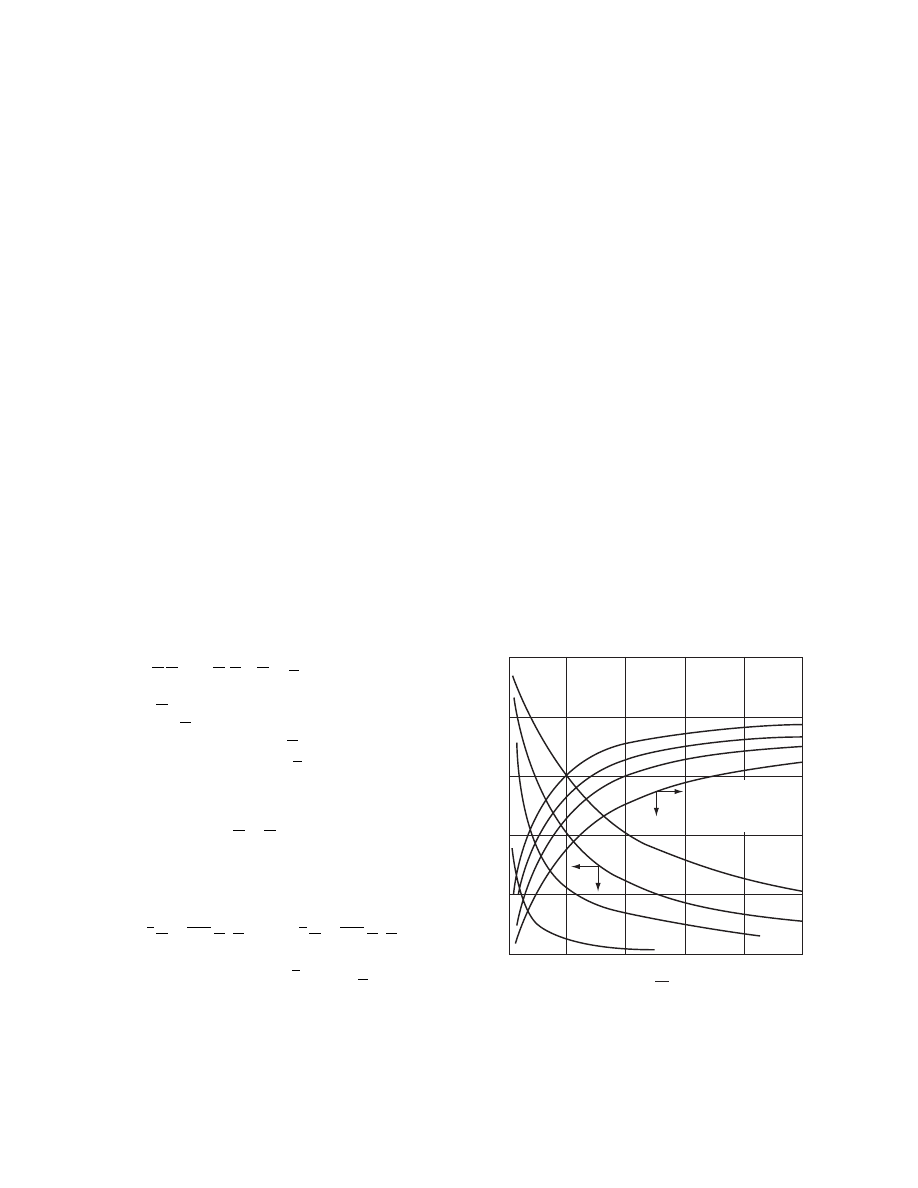
«
1
i
,
j
¼ «
1
i
þ «
1
j
1 (13 : 27)
where «
i
is the emis sivity of the glass , «
j
is the emis -
sivity of the absorber , and s is the Stefa n–Boltzm ann
constant .
Heat conductiv ity in soli d elements of d thickne ss
for surfa ce unit is
K
(c )
i
,
j
¼ k d
1
(13 : 28)
Conduct ivities (convect ion) for the outer surface
units are
K
(k)
i
,
o
¼ h (13 : 29)
where h is the heat transfer coeffici ent that depend s
on win d velocity. Approxi mate co rrelati ons for h as a
functio n of wind veloci ty w are
h
¼ 5: 7 þ 3: 8w for w < 5 m=s
h
¼ 7: 6w for w 5 m=s
(See Ref . [95] for furth er detai ls on win d effects.)
Heat trans fer co efficien ts for forced and natural
convecti on in air gaps can be calculated from correl -
ations [43,56]. Substituti ng, on the basis of the branch
and Equat ion 13.23b, the f
i,j
values
into the nodal equati ons, we get the foll owing syst em
of eq uations for the ne twork:
C _
T
T (t )
þ K (T , t )T ¼ f( I , T
s
, T
o
, t ) (13 : 30)
where C is the diagonal matr ix of the nodal he at
capacit ies, _
T
T is the column vector of the tim e deriva tes
of the noda l tempe ratur es, T is the column vector of
the nodal tempe ratures, and is the source vector .
The solution of the syst em (Equ ation 13.30) can be
obtaine d num erically by tim e discr etizati on. Becau se
of the nonlinear ities, the integ rated mean value of the
condu ction matr ix ^
K
K
¼ ^
K
K (T (t ) ) for a given pe riod of
time can be created and a nume rical scheme of one or
two time level s can be app lied [96] . Favo rable resul ts
have been obtaine d by the linear Galerkin scheme [97] :
1
3
^
K
K
þ
1
2Dt
C
T
(k )
¼
1
6
^
K
K
þ
1
2Dt
C
T
(k
1)
þ
1
6
f
(k )
þ 2f
(k
1)
h
i
(13 : 31)
In this equatio n, k is the number of discr ete time
section s in the step- by-step solution (t
¼ k Dt ).
Meteor ologic da ta are at one ’s disposa l hour ly, so in
the calcula tion a time step of 1 h can be app lied. For
stabili ty it is advantag eou s if the syst em of equ ations
is well conditio ned. Accor dingly , heat capacit ies of
insignifican t influ ence are best neglected . As a resul t
of calcul ation, the time depen dence of the med ium
outlet tempe ratur e, as well as the time varia tion of the
approxim ate tempe rature distribut ion of the col-
lector, is obtaine d. The resul ts can be used for inst ant-
aneous an d steady -state effici ency diagra ms, for
collector design an d optim ization , and for the solu-
tion of process control problem s [33, 34,43,50, 56,98] .
It is of co urse desirab le to verify the calcul ation re-
sults with exp erimental measur ements wher e possibl e.
13.5.1 .5 The rmal Perform ance of
Flat -Plate Collectors
Figure 13.25 sho ws the ch aracteris tics of a singl e-
coveri ng, air-type colle ctor (blac k absorber ) obtaine d
by calcul ations [37] . In the figu re, DT is the rise in
tempe rature of air in the colle ctor (D T
¼ T
c,out
T
c,in
), h is the instan taneous effici ency, and _
m
m is the
mass flow rate of air. The pa rameter in the figure is
the surfa ce area per unit colle ctor lengt h (series con -
nectio n).
, the inst antaneous effici ency and
the outlet temperatur e of a liqui d-type colle ctor (sin -
gle-coveri ng, steel finned tube s, black absorber ) are
illustrated as a functi on of liqui d hea t cap acity flow
0
1
5
10
20 m
2
0
5
1 m
2
10
10
20
20
30
40
50
0
0.2
0.4
0.6
0.8
1.0
0.1 0.2 0.3 0.4 0.5
T
o
= T
air, in
= 25
⬚C
w = 5 m/s
1 glass
ΔT,K h
%
m, kg
s
.
FIGURE 13.25 Main characteristics of an air-type collector.
(From Imre, L. and Kiss, L.I., in Numerical Methods in Heat
Transfer, Vol. 2 (R.W. Lewis, K. Morgan, and B.A.
Schrefler, Eds.), Wiley, Chichester, England, 1983,
ß
2006 by Taylor & Francis Group, LLC.

rate [37]. The parame ter is the irra diation. As the
variations of I are accompani ed by nonlinear he at
transfer resistance varia tions, the curves for diff erent
I values deviate. The entry tempe ratur e of the med-
ium is equal to the outsid e tempe ratur e (T
c,in
¼ T
o
).
Fig ure 13.27 illu strates the inst antaneous effi-
ciency of a liquid -type collec tor as a functi on of the
inlet tempe rature with single (Figur e 13.27a ) and
double (Figur e 13.27b) coveri ng [37] . The parame ter
is the outsi de tempe rature. With an increa se in the
inlet temperatur e, the mean tempe ratur e ( T
a
)
av
and
the heat loss of the absorber increa se whi le the ef-
ficiency deteriorat es. With double coveri ng, the effi-
ciency wi th a higher inlet tempe ratur e is great er than
that with a single coveri ng.
shows the inst antaneous effici ency
diagra ms for different colle ctors. It can be seen from
this figure that the inst antaneous efficien cy of col-
lectors now in gen eral use can be as high as 50–60% .
The value of daily long-te rm effici ency amounts to
approxim ately 25–30% .
On the basis of the long-term collector efficien cy,
the collector surfa ce necessa ry for the operatio n of the
dryer can be de termined. Becau se the instantaneou s
efficien cy of the collector is over one part of ope ration
time great er than the long-te rm effici ency, the ene rgy
utilized by the c ollector over this period is greater
than the necessa ry value. The surplus energy can
be stored for the period when there is no solar en ergy
available. In cheap, simple construction dryers without
heat stora ge, this surplus energy can be used for so me
tempor ary enhan cement of the drying proce ss if the
material to be dried can withstan d it.
13.5.2 H
EAT
S
TORAGE FOR
S
OLAR
D
RYERS
From a therm al view point heat storage of solar dryers
can be classified into two main grou ps:
1. Directly irra diated heat storag e
2. Heat stora ge charged by the working med ium
of the collector
0
50
100
20 40 60
0
50
A = 5 m
2
1 glass
100
T
c,out
⬚C
80 100
h
%
250 W/m
2
250 W/m
2
500 W/m
2
T
o
=
T
c,in
= 25
⬚C
w = 5 m/s
(
mc
p
), W/K
I = 1000 W/m
2
1000 W/m
2
FIGURE 13.26 Main characteristics of a liquid-type col-
lector. (From Imre, L. and Kiss, L.I., in Numerical Methods
in Heat Transfer , Vol. 2 (R.W. Lewis, K. Morgan, and B.A.
Schrefler, Eds.), Wiley, Chichester, England, 1983,
T
o
=
T
c,in
T
o
=
T
c,in
T
c,in
⬚C
T
c,in
⬚C
T
o
= 30
⬚C
20
⬚C
10
⬚C
T
o
= 30
⬚C
20
⬚C
10
⬚C
I
o
= 500 W/m
2
W
= 5 m/s
1 glass
I
o
= 500 W/m
2
W
= 5 m/s
2 glass
0
20
40
60
50
(a)
(b)
80
0
20
40
60
80
h
%
50
h
%
FIGURE 13.27 Instantaneous efficiency of a liquid-type
collector as a function of inlet temperature; parameter is
the ambient temperature: (a) single covering; (b) double
covering. (From Imre, L. and Kiss, L.I., in Numerical
Methods in Heat Transfer, Vol. 2 (R.W. Lewis, K. Morgan,
and B.A. Schrefler, Eds.), Wiley, Chichester, England, 1983,
chap. 15.)
ß
2006 by Taylor & Francis Group, LLC.

The storage tempe rature of directly irradiat ed he at
storage is not lim ited by the collec tor outlet tempe ra-
ture of the medium . How ever, in heat stores warmed
by the worki ng med ium the maximu m tempe rature
cannot exceed the colle ctor outlet tempe ratur e.
The aim of heat stora ge is to store surplus ene rgy
appeari ng in strong radiation periods ; howeve r, the
aim may also be to store enou gh energy for full-sc ale
drying ope ration at night as well. When determ ining
the ne cessary surfa ce area of the collector, the
amount of energy to be store d must also be taken
into acco unt.
13.5.2 .1 Direct ly Irra diated Heat Storag e
Directly irradiated heat storage of solar dryers can
first be used in direct air systems. The collector
sketche d in
storage. The phase-change material is placed in a
plastic honeycomb matrix casing. Thermal expansion
is made possible by additives. The outer surface of the
plastic cells containing the phase-change material
take over the function of the absorber. The thick-
ness of the cells is limited by phenomena occurring
in the course of phase change [38,39,101,102]. There-
fore the mass to be placed on 1 m
2
is also limited, and
so is the overall amount of storage heat.
The primary purpose of applying directly irradi-
ated latent heat storage is to attain an equalizing
effect during cloudy periods over the day as well as
to lengthen the daily drying time. To show the ther-
mal behavior of a collector integrated with latent heat
storage, Figure 13.29 is presented. The temperature–
time function was determined by calculation using the
simulation model described above and checked by
measurements. The heat capacities of other elements
of a heat storage collector are negligible when com-
pared with that of the heat storage. The effect
of latent heat was built in the volumetric heat cap-
acity of the absorber and simulated [38,103,104]
(data: material, CaCl
2
6H
2
O; phase-change tem-
perature, 298C; latent heat, l
¼ 209 MJ/m
3
; size of
cells, 9 mm
10 mm; mass/m
2
, 6.3 kg).
0.2
1
2
3
4
0.2
0.3
0.4
0.5
0.6
0.7
h
0.8
0.1
0.4 0.6 0.8 1.0 1.2 1.4 1.6
I
T
out
− T
in
FIGURE 13.28 Efficiency diagrams of collectors of different
construction: (1) black absorber, one covering; (2) black
absorber, two coverings; (3) selective absorber, one cover-
ing; (4) vacuum collector.
+
+
+
+
+
+
++ +
+
+
+
+
+
+
++
+
+
+
+
+
+
+
+
+
+
+
+
+
+
+
+
+
+
+
+
+
+
+
+
+
+
+
+
+
+
+
+
+
+
+
+
+
+
+
+
+
+
+
+
+
+
+
+
+
+
+
+
+
+
+
+ + +
+
+
+
+ +
+
+
+
+
+
+
+
Calculated
Measured
700
600
500
400
300
200
100
20.00
15.00
10.00
6.00
20
30
40
50
60
Ambient
parameters
T
out
T
a
⬚C
I W/m
2
T, h
I(T )
T
o
=T
in
(T )
T
c,out
(T )
T
a
(T )
FIGURE 13.29 Behavior of air-type collector integrated with phase-changing filling (functions of T
out
and T
a
determined by
simulation and measurements).
ß
2006 by Taylor & Francis Group, LLC.
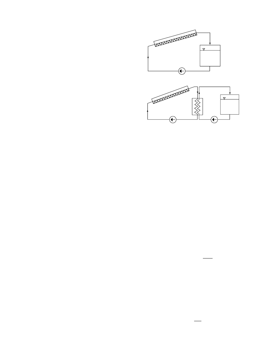
The absorber may be a solid (e.g., concrete) wall
with a black coating. In the case of solar dryers, this
solution is justified if the wall is the dryer housing wall.
Its operating principle is the same as that of the Trombe
wall used in passive solar heating [56]. (For collector-
integrated solar water heaters, see Refs. [105,108].)
13.5.2 .2 Heat Storage Char ged by the Medi um
of the Colle ctor
In he at stora ge war med by the workin g medium , the
maximu m tempe rature canno t exceed the maximu m
tempe rature of the medium leavin g the colle ctor. As
storag e mate rial, various solids, water, various pha se-
change mate rials, as well as ch emical storage mate r-
ials may be use d.
The tempe rature of the medium enteri ng the stor-
age is equ al to the tempe ratur e of the medium leaving
the collector if the heat loss of the duc t is ne gligible.
The medium in liquid syst ems after leaving he at stor-
age flows ba ck into the colle ctor. With air syst ems
sometime s the air leavi ng the he at storage unit is
exhaust ed into the atmos phere.
W ater-type heat stora ge may be a direct or indir -
ect syst em. In direct systems the working medium
flows in a closed circuit (Figur e 13.30a ). In indir ect
systems, the worki ng medium can be liquid (anti -
freeze liqui ds in some ca ses). The closed colle ctor
circuit and the closed stora ge circui t are connec ted
through a heat exchanger (Figur e 13.30b) . In wat er
heat storage, two types of storage syst ems are
employ ed: stratifie d a nd well-mixe d storag e.
In stratifie d wat er stora ge the war m water from the
collector enters near the top of the tank; the fluid led
back to the co llector is draw n from the bottom of the
tank by a pump. Thus in the uppe r layers of the tank
there is always warm wat er, an d the low er layers co n-
tain c old water. The adva ntage of this method is that
the colle ctor receives cold water as long as co ld layer
exists near the bottom of the tank [56,106,1 07]; acc ord-
ingly, the collector works wi th approxim ately constant
efficien cy. The thickne ss of the trans ient tempe rature
zone is determined by the time bounda ries of the
tempe rature changes of the wat er coming from the
collector. In ope ration pe riods of reduced radiat ion,
the tempe ratur e of the water from the colle ctor is low er
than that of the tempe rature in the top layer. This
water descends an d causes mixing in the tank.
W hen using store d hot water (
) , the
water is led into the air–w ater he at exch anger from
the top of the tank . The return ing water enters at
the bottom of the tank . The mass of wat er in the
tank therefo re makes on chargi ng a slow downward
motion and on dischar ge a slow upwar d motio n. The
rate of this motion de pends on the mass flow rate of
the wat er (and on other effe cts, see below). The ar-
rangem ent shown in Figure 13.31 allows regu lation of
the wat er flow rate, the change of operatio nal mod e,
and a sim ultaneo us drying– chargi ng operatio n.
The amount of heat to be store d Q can be deter-
mined from the heat deman d of the dryer:
Q
¼
ð
t
0
f
( t ) dt (13 : 32)
Storage tempe ratur e is limit ed by the fluid tempe ra-
ture that can be atta ined in co ntinuous ope ration
of the collector. In a direct stora ge system (Figur e
13.30a ) disre garding heat loss from the pipes, the
tempe rature of the medium co ming from the colle ctor
can be calculated by using
:
(T
c
,
out
)
av
¼ ( T
c
,
in
)
av
þ
A
c
I h
_
m
mc
p
(13 : 33)
The heat to be store d in t chargi ng time, neglecting
the he at loss, is
Q
¼ M
T
c
T
[(T
c
,
out
)
av
(T
c
,
in
)
av
]
¼ _
m
mc
p
[(T
c
,
out
)
av
(T
c
,
in
)
av
]t
(13:34)
Hence,
M
T
¼
_
m
mc
p
c
T
t
(13:35)
C
C
T
T
P
P
1
P
2
(a)
(b)
H
FIGURE 13.30 Water-type heat storage: (a) direct; (b) in-
direct (C, collector; T, tank; P, pump; H, heat exchanger).
ß
2006 by Taylor & Francis Group, LLC.
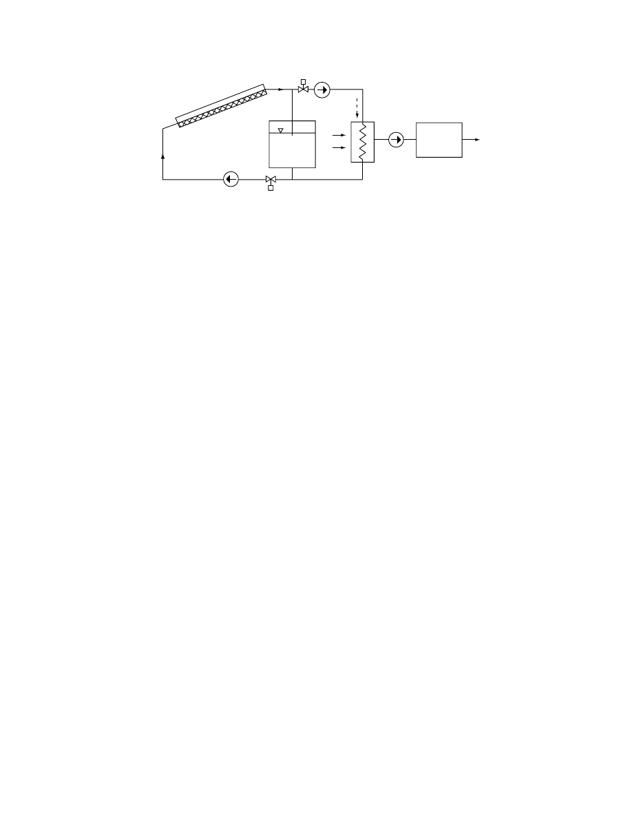
This calcul ation is app roximate becau se it refer s to
continuous ope ration asses sed from time average s
and does not co nsider existenc e of stratific ation and
the co nsequences of he at loss. A more exact calcul a-
tion can be made from the discr etized model of the
storage tank with due regard to heat loss [56,106,1 07].
In indire ct storage systems (
), the
tempe rature of hot water entering the store T
T
can
be calcul ated from the effectiven ess H of the he at
exchanger ( _
m
m
c
c
pc
_
m
m
T
C
PT
):
T
T
,
in
¼ T
T
,
out
þ H ( T
c
,
out
T
T
,
out
) (13 : 36)
The relationshi p corres pondin g to
can be written wi th the respect ive values of T
T,in
and
T
T,out
.
In the case of stratifie d heat storage the mass flow
rate of the collector medium is held during ch arging
at a relat ively low v alue for the purpo se of gett ing as
high a value of T
c,out
exit tempe ratur e as pos sible. A
disadva ntageous consequen ce (
) is
only moderat e effici ency.
W ith a well- mixed heat stora ge system, the tem-
peratur e of the water in storage is practi cally unifor m.
Mixin g of the wat er can be prod uced by several (even-
tually simulta neous) effe cts. These are a large mass
flow rate and inlet velocity, horizont al locat ion of the
tank, in an indir ect syst em the he at exch anger located
at the bottom of the tank, ba ffle plate s in the tank,
and the use of a circulati ng pump for mixi ng.
In the course of charging the perfectly well-mixed
heat storage, the temperature of the mass of the water in
storage and the temperature of the water returning
to the collector rises (
). As a
consequence, the collector works at an ever-increasing
temperature level with an ever-decreasing efficiency.
However, its long-term efficiency is not necessarily
lower than that of stratified storage collectors, although
these receive, during a major part of charging, an
entering fluid of low temperature. That is, the mass
flow rate of the working medium can be considerably
greater in collectors of well-mixed heat storages as there
is no interest in a significant increase of fluid tempera-
ture in the collector. With a higher mass flow rate,
however, the efficiency of the collector will increase
(
). Taking the usual daily 6–8 h char-
ging time, stratified heat storage and well-mixed heat
storage are about equal from a thermal point of view.
In the operation of a solar dryer, techn ologica l
interest is attach ed to a suffici ently high tempe rature
of the fluid leavi ng the colle ctor for preheat ing the
drying air. At the same time, during certa in periods of
operatio n, simulta neous acti ons must be carried out
for chargi ng the store and for drying (see Figure
13.31). Conse quently , the mass flow rate of working
medium of the collector must be lim ited to reach the
necessa ry exit tempe ratur e of the colle ctor. Ther efore,
in the operatio n of solar dr yers, the stratifie d he at
store is prefer red.
In solar dryers with air-type co llectors rock-bed
storage (crus hed stone or pebbles of 2–4 cm size) is
used most co mmonly . When selecting the mate rial for
the rock or pebble bed, amo ng othe r consider ations ,
there is the que stion of the pressur e drop across the
bed. The flow resistance of a pe bble is usuall y smal ler
than that of crushed rock. Uniform pebb le or rock
size must be chosen to obtain unifor m air dist ribution
in the bed . The necessa ry mass of rock-bed or pe bble-
bed he at storage is typicall y abou t threefold that of
water- type he at stora ge.
Because of the point contact between the particles in
the rock bed, the heat conduction is negligible. There-
fore, rock beds work practically as stratified heat stores
no matter the arrangement for air inlet and exhaust.
Duri ng chargin g of the rock-bed he at store, the
cooling of the air at the entry spot takes place within a
layer of a certa in thickn ess. If the en try tempe rature
of the air was co nstant, this layer of changing
V
2
V
1
P
2
P
1
H
F–A
T
Air
Fan
Dryer
FIGURE 13.31 Connection of water-type heat storage to the dryer (H
F
A
, fluid–air heat exchanger; V
1
and V
2
, valves).
ß
2006 by Taylor & Francis Group, LLC.
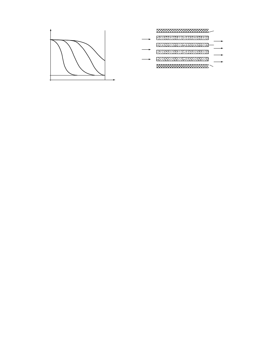
tempe rature woul d pus h down deep er and deep er
(Figur e 13.32). How ever, because dur ing the day
periods of varyi ng radiat ion intensit y occu r, it is
possibl e that dur ing c ertain periods of the day the
tempe rature of entering a ir is lower than that of
the he at-storin g mate rial at the place of entry. In
this case the air in the entry layer co ntinues to get
warmer and deliv ers the earlier stored he at into dee-
per layer s of the storage, to a low er level of tempe ra-
ture, and en larges the wi dth of the layer of chang ing
tempe rature. The princip le of app roximate calcul a-
tion of rock- or peb ble-be d heat stora ge is simila r to
that of a stratifie d water-type heat stora ge.
present the arrange ment of solar dryers
equipped wi th peb ble-bed he at stora ge.
Bet ween water an d soli d-bed he at storages there is
a so-cal led trans itional option hea t storage with the
aid of fluid -filled cans. An e xample of this is shown in
. In he at storage devices warmed by a
workin g fluid , phase-c hange mate rials can also be
used [38, 39,101 ,102]. Phas e-change energy storage
has tw o main advantag es. One advantag e is that the
energy stored per unit volume of the store is signi fi-
cantly greater than that for pe bble-be d heat stora ge,
for exampl e. One of the cheapest mate rials wi th good
workin g cha racteris tics [109] is Na
2
SO
4
10H
2
O; wi th
this the pro portion of stored energy is ab out fourfo ld
(latent heat l
¼ 251 kJ/kg; phase-c hanging tempe ra-
ture, 32 8 C) . Als o, the fixed pha se-cha nge tempe rature
reduces tempe rature varia tions.
The ap plication of phase-c hanging materials
(PCM ) also involv es certain prob lems. Eutectic salt s
are suscep tible to phase separat ion [110, 111]. To
avoid this [38,112] it is desirab le to make the PCM
contai ners thin (Figur e 13.33) . Anothe r phase-c hange
material is pa raffin wax ( l
¼ 20 9 kJ/kg) . Its disad-
vantage is inflamm ability.
A general problem with PCM stores is the fabri -
cation of an inexpensi ve casing resi stant to corrosio n.
For some PCMs, degrada tion has been experi enced
over the course of repeated cycli ng. The choice be -
tween phase change and sen sible he at stora ge must be
made on economic grounds.
Heat stora ge by ch emical react ions has also been
studied [56, 112,11 3]. These methods have not pro -
gressed beyo nd the experi menta l stage and do not
appear applic able for solar drying applic ations.
Ener gy stora ge in adsorbent bed s can be ap plied
to solar dryers because air of reduced humidi ty co n-
tent leaks from the adsorbent . Silica gel, activated
aluminu m ox ide gel, zeolites, and various molec ular
sieves can be used as adsorben ts [27,29,11 4]. Deta iled
analys es a nd optim ization proced ures are know n for
energy stora ge in timber dryers [29] and garlic dryers
[12]. The ap plications of adsorbent energy stora ge are
also found in complex syst ems [25] . Althou gh the
advantag es are undisput ed, the costs of adsorben ts
and the auxiliary equipment are consider able.
13.6 SIMULATION OF SOLAR DRYERS
13.6.1 P
URPOSE OF
S
IMULATION
Simulati on is an impor tant tool for design an d ope r-
ation control [200, 201,22 0]. For the designe r of a
drying system, simulat ion makes it possibl e to find
the optim um design and operating parame ters. For
the designe r of the co ntrol system, simulat ion pro-
vides a means to devise control strategies and to
analyze the effects of disturbances.
13.6.2 M
ETHODS OF
S
IMULATION
Various simulation models for solar processes have
been reported. They differ mainly in the assumptions
made and strategies employed to solve the model
equations. A majority of the models refer to solar
heating [115–117]. One widely used simulation pro-
gram is the TRNSYS [56,118]. The f-chart method for
solar heating of buildings is also well known
[56,119,120]. Other relevant references are design of
T
T(T
≈
0)
L
T
in
T
1
T
2
T
3
T
4
FIGURE 13.32 Passing of temperature wave in a gravel-bed
heat storage with depth L (T
in
¼ constant).
1
1
2
T
OUT
T
in
m
a
.
FIGURE 13.33 Example for placing phase-changing fillings
in the heat storage: (1, insulated wall; 2, containers; _
m
m
a
¼
constant).
ß
2006 by Taylor & Francis Group, LLC.

closed- loop solar syst ems [121], co ntrol and optim iza-
tion [117] , and process sim ulation based on a stochas -
tic model [58] and for a resi stance netw ork [56,122].
Selcuk et al. [5,123] describe the simulation of a
shelf-type dryer. Close [124] worked out the simulation
of an air-type solar drying system equipped with gravel-
bed heat storage using a 10-node discretized model
for the heat storage and forward finite difference tech-
nique for solving the equation system. Imre et al.
[25,125] presented a simulation of solar dryer for alfalfa.
Dagu enet [187, 188] elabora ted a simplified meth-
odology for the calcula tion of solar -assist ed convect-
ive dryers co nsidering the mete orologi cal conditio ns.
Norto n and Hob son [189] suggest ed a finite difference
numeri cal analysis for chimney -type solar dryers for
drying crops. Tigu ert and Pui ggali [190, 191] publis hed
a pe rformance model for a solar natural chimney dr yer
and are given in
. The one-dim ensional ,
concen trated parame ter model consis ts of four elem -
entary mode ls (i.e., for the co llector, for the heat stor-
age in dayti me an d in nighttim e, an d for the material
situated in thin layers in the drying space) .
Steinf eld and Segal [192] propo sed a sim ulation
model for a solar thin- layer drying pro cess includi ng
the techn ique of estimat ing the solar radiation, the
procedu re of obt aining the therm al pe rformance of a
solar air- heater, and an analysis of the dr ying pro cess
based on the Lewis analogy an d the equilibrium mois -
ture con tent (EMC ) concep t. Hasnaoui et al. [186]
elabora ted a one-dim ensional model for a solar
dryer of static thick be d.
Patil and Ward [194] prepared a simu lation mo del
for a solar -assisted bin dryer wi th and wi thout mixing
in atmos pheric air. The mod el consis ts of the pa rt
model of the solar colle ctor an d the part model of
the thick through- flow layer divide d into thin layer s.
W eitz et al. [195] prop osed a sim ulation model for
a multishel f type semi artificial solar dryer for dry ing
process es in thin layer based on Lui kov’s theo ry by
consider ing the shrinka ge of the mate rial. Mah apatra
et al. [206] elabora ted simulat ion model for direct ly
irradiat ed solar dryer with integrate d colle ctor.
13.6.3 S
IMULATION
M
ODEL OF
S
OLAR
D
RYERS
Solar dryers are therm ohyd raulic syst ems composed
of various uni ts such as colle ctor, heat stora ge, he at
exchanger, pump, ventilat or, tubes, v alves, closing
and control ling devices , and the dryer. A sim ulation
model of solar dryers is therefore made up of three
main sub systems:
1. Model of the flow subsystem
2. Model of the therm al subsyst em
3. Model of the drying volume
13.6.3 .1 Mo del of the Flow Subsyste m
The uni ts of the solar dryer are joined into a syste m
by flowi ng media ; therefore a model of the syst em is
best built on the flow mode l of these media [126]. The
number of flow models is necessa rily equal to the
number of worki ng media in the solar dryer.
The flow mod el serves to determ ine the mass flow
rates of the flowi ng media. In the follo wing section
the mass flow network (MF N) modeli ng method is
present ed. The M FN model of solar dryers essential ly
divide s the flow syst em into discrete parts in which the
effects causing pr essure changes are modeled by net-
work elem ents; the ne twork elemen ts are joined
accordi ng to the flow path of the medium .
Pr essure c hanges can be produced by extern al a s
well as internal effe cts. An exampl e for an extern al
effect is due to the pump or the fan. Intern al effe cts
can be the consequ ences of cross- sectional ch anges,
heat trans fer, acc eleration or deceler ation, and flow
resistance s. Some of the most impor tant MFN elem -
ents are given in
In the MFN model the flow resistance s and pres-
sure sources are dep endent on heat flow or tempe ra-
ture. Dis cretizat ion has to be made so that over an
individu al discr ete secti on the tempe ratur e-depende nt
charact eristics can be exp ressed by lumped values
with suffici ent acc uracy. Pip es, whi ch can be taken
as isot hermal and have a constant cro ss-section can
be modeled as a single flow resistance .
Flo w resistance s are charact erized for the jth sec-
tion on the ba sis of the pre ssure drop Dp
j
and the
mass flow rate _
m
m
j
(see Table 13.2):
R
j
( _
m
m
j
, T
m
)
¼ Dp
j
_
m
m
1
j
(13 : 37)
For the simulat ion it is necessa ry to know the state
function s D p( _
m
m , T, n) of the pumps and fans used.
shows the arrange men t of an indir -
ect system solar alfalfa dryer with water- type hea t
storage servin g simu ltaneou sly as the hot water sup -
ply [25] . (For a detailed description,
. )
The syst em has tw o worki ng media . The primary
flow circuit is closed; its medium is water. The sec-
ondary flow circuit is open ; the working medium is
air. Thermal interacti on of the worki ng media of the
two circuits is carried out by a heat exchanger.
Figure 13.34b and Figure 13.34c outline the reduced
MFN model of the primary and secondary flow circuits,
respectively. In the reduced model of the primary flow
circuit (Figure 13.34b), R
c
and R
H
are the resultant flow
resistances of the collector and the heat exchanger,
respectively, including the resistances of the pertinent
pipe sections. (In the detailed model there are several
partial resistances corresponding to the discretization.)
ß
2006 by Taylor & Francis Group, LLC.

TABLE 13.2
Identification of the Elements of the Mass Flow Network Model
Element
Relationship
Note
Flow resistances
R
¼ Dp _
m
m
1
Tube friction resistances
From Poiseuille
equation ( _
m
m
¼ r Aw)
Laminar flow
R
¼
chL
rd
2
h
A
Turbulent flow
R
¼
2fL
rd
h
A
2
_
m
m
From Fanning equation
Shape resistance
R
¼
§
2rA
2
From Dp
¼ §
r
2
w
2
Jump-like change of
cross-section
R
¼ j
B
_
m
m
2r
1
A
2
1
1
A
2
2
j
B
: Borda–Carnot coefficient
Pressure sources
Centrifugal pump and fan
Dp
¼ A þ B _
m
m
þ C _
m
m
n
Equation of the characteristic
Change of cross-section
(A
1
A
2
)
Dp
¼
_
m
m
2r
1
A
2
2
1
A
2
1
From Bernoulli equation
Hydrostatic pressure source
Dp
¼ rg (z
1
z
2
)
z
1
, z
2
level heights
Closed thermosyphon loop
Dp
¼ g f r(T(z) )dz
T(z): temperature as a function
of the level height z
Heat input pressure source
between points 1 and 2 of a
pipe (A
¼ constant)
Dp
¼
R
(c
p
)
av
r
av
f
h
_
m
m
_
m
m
2
2A
2
1
r
1
1
r
2
From enthalpy balance equation
Acceleration pressure source
Dp
¼ raL
r
¼ constant
Mass flow source (independent)
_
m
mr
1
¼ constant
Volumetric pump
Tank
P
A
Pump
To hot
water
consumers
Cold water
in
Pump
(1)
Air in
Air
out
Solar
collectors
Dryer
(Static bed)
Fan
Heat
exhanger
Outer
air
in
(2)
1
3
2
4
A
m
c
2
1
3
4
R
2
R
C
R
P
R
1
R
3
R
4
R
H
R
d
R
out
R
IN
R
B
R
H
ΔP
S
Δp
f(m
a
·T)
Δp
1
f(m
F
T)
(b)
(c)
(a)
FIGURE 13.34 Solar-assisted indirect drying system for alfalfa: (a) scheme of system; (b) reduced mass flow network model
of the fluid; (c) reduced mass flow network model of the airflow system.
ß
2006 by Taylor & Francis Group, LLC.

, R
d
is the flow resistance of the forward
pipe section, R
1
through R
4
are the variable shape res-
istances of the control valves, and Dp is the pressure
source due to the pump.
In the mode l of the secondary flow circuit, Dp
s
is
fixed by the atmos pheric pressure , Dp
f
is the pressure
source of the fan, R
H
is due to the heat exch anger,
and R
in
and R
out
, respect ively, are the inlet and outlet
flow resi stance s of the dryer its elf. R
B
refer s to the
varyin g flow resi stance of the be d with thickne ss
changing over time.
The syst em of equatio ns of the MFN model co n-
sists of the nodal eq uations (Equati on 13.38) , the loop
equati ons (Equati on 13.39), and the branch eq uations
(Equati on 13.40). If the netw ork contai ns m numb er
of independen t noda l poin ts, i num ber of bran ches for
each node , l numb er of independen t loop s, and j
number of branches for each loop, the eq uation sys-
tem can be writt en in the form
X
i
_
m
m
i
!
m
¼ 0 (13 : 38)
X
j
[ Dp
j
þ D p( _
m
m , T , n)]
I
¼ 0 (13 : 39)
Dp
j
¼ R
j
( _
m
m
j
, T ) _
m
m (13 : 40)
The tempe ratur e-depend ent elem ents of the MFN can
be identified from the therm al subsystem model.
13.6.3 .2 The rmal Subsyst em Model of the
Pr imary Circui t
The therm al sub system model of the prim ary circui t
consis ts of the mode ls M of the co llector M
c
, the he at
exchanger M
H
, and the heat stora ge M
T
, in acco rd-
ance wi th the mod e of ope ration. The modes of ope r-
ation are as follows (Figur e 13.35):
M ode I: Valves 2 and 3 are closed, an d 1 and 4 are
open ; the air pa ssing throu gh the heat excha n-
ger can be preh eated by the wat er coming from
the collector (see also Figure 13.34a).
Mo de II: Valve s 1 an d 3 are closed, and 2 an d 4
are ope n; the water in the tank can be heated by
the spiral pipe P.
Mode I
þ II: By partial closing of valves 1 and 2
modes I and II can be maintained simultaneously.
Mo de III: Valves 1 an d 4 are closed, and 2 and 3 a re
open ; colle ctors are not ope rated. The wat er of
the tank is led to the he at exchanger of the dryer.
(A is the auxiliary heater ; see Figure 13.34a .)
13.6.3 .2.1 The rmal Mod el for the Col lector
The model of the collector can be built according to
different model concepts. A detailed description of heat
flow network model is given in
. The
equations of this model are given in
13.6.3 .2.2 The rmal Mod el for the Heat Exch anger
The therm al model M
H
of the wat er–air heat exchan -
ger of the system outlin ed in Figure 13.34a serves to
determine the outlet tempe ratur es T
F
’’
and T
A
’’
of the
working media , when the inlet tempe ratur es and the
thermal cap acity flows _
C
C
¼ _
m
mc
p
in modes I, I
þ II, and
III are known. Bec ause eventual trans ients are slow ,
the effect of the therm al capacities is disre garded.
Effect ivenes s H of the hea t excha nger as a func-
tion of the rati o _
C
C
A
/ _
C
C
F
must be known for the calcu-
lation. For an adiabat ic heat exchanger,
T
00
A
¼ T
0
A
þ H ( T
0
F
T
0
A
) (13 : 41)
T
00
F
¼ T
0
F
H
_
C
C
A
_
C
C
F
( T
0
F
T
0
A
) (13 : 42)
13.6.3 .2.3 Model for Heat Storage
For the dryer in Figure 13.34a , the tank of the warm
water system of the farm is used a s he at stora ge. The
emerg ency energy source A is built into the tank.
The he at stora ge is of the well-mixe d type. The
model for he at stora ge serves for determ ining the
outlet tempe ratur e T
F2
of the colle ctor working med-
ium and the temperature T
T
of the water in store. The
equations of the storage with C
T
¼ M
T
c
p
at any time,
for the case of _
C
C
c
¼ _
m
m
c
d
p
hot water consumption, are
I
II
I
+ II
III
M
C
M
C
M
C
M
T
M
T
M
H
M
T
M
H
M
H
FIGURE 13.35 Thermal subsystem models according to the operating modes of the solar dryer.
ß
2006 by Taylor & Francis Group, LLC.

C
T
d T
T
d t
þ _
C
C
c
( T
T
T
w
,
in
)
¼ _
C
C
F
( T
F1
T
F2
)
þ f
A
þ f
T
(13 : 43)
T
F2
¼ T
T
þ ( T
F1
T
T
) exp
hA
_
C
C
F
(13 : 44)
where T
w,in
is the tempe ratur e of en tering water, f
A
is
the heat flow rate of the auxiliary energy source, f
T
is the rate of heat loss from the storage tank, T
F1
is
the tempe ratur e of wat er from the colle ctor, and
A is the heat transfer surface of coil heater .
13.6.3 .2.4 Mod el for the Cont rol System
The control stra tegy of dryer ope ration must be
known for the simulat ion of the syst em, an d the ope r-
ating model for the control syst em ha s to be built into
the sim ulation model. The model contai ns the co ndi-
tion syst em of the ope ration mode change, with the
values of resistance s R
1
, . . . , R
4
)
ordered to the corres pondin g poin ts of tim e or to the
limit values of the state charact eris tics of the working
media of the mate rial to be dried and of the atmos -
pheric states. An adva ntageous solut ion is optimu m
control by sampl ing, using micr oprocessor s (for opti-
mum tempe rature con trol, see, e.g. , Ref . [127] ).
13.6.3 .2.5 Coupl ing Equ ations
Insofa r as heat losse s from the pipes be tween the units
are disre garded, the tempe rature of the medium leav-
ing the preced ing unit is equal to the inlet tempe rature
of the adjoini ng unit:
T
c
,
out
¼ T
0
F
T
c
,
out
¼ T
F1
T
0
F
T
F1
(13 : 45a)
T
c
,
in
¼ T
00
F
T
c
,
in
¼ T
F2
T
00
F
T
F2
(13 :4 5b)
If the heat losse s from the con necting pipes are taken
into co nsideration [45], further compo nent mod els
must be de veloped for de terminat ion of the losse s.
In this case the cou pling equ ations are interprete d
for the relation of loss part models and the models
of the units . If the loss heat flow rate of the colle ctor–
storag e pipe is f
C
T
, that of the stora ge–collec tor
duct is f
T
C
and those of the colle ctor-he at excha n-
ger-co llector pip es accordi ngly are f
C
H
and f
H C
,
respect ively, and the coupling equatio ns betw een the
units can be written for the different modes of ope r-
ation on the basis of the enthal py balance e quations
T
0
F
¼ T
c
,
out
f
C
H
_
C
C
F
(13 : 46a)
T
F1
¼ T
c
,
ou t
f
C
T
_
C
C
F
(13 :4 6b)
T
c
,
in
¼ T
00
F
f
H
C
_
C
C
F
(13 : 46c)
T
c
,
in
¼ T
F2
f
T
C
_
C
C
F
(13 :46 d)
In the combined mode I
þ II of ope ration , the inlet
tempe ratures can be de termined from the mixing e n-
thalpy ba lance eq uation.
13.6.3 .3 The rmal Subsyst em Model of the
Sec ondary Circuit
The airflow circuit of the syst em in Figure 13 .34a is
open; thus the ope ration of the dryer doe s not react to
the ope ration of the primary circuit. In the case of
solar dry ers, with parti al recir culation of the drying
air [25] , the conditio n of the air enteri ng the dry er
depend s on the operati on of the dryer itself. Accor d-
ingly, with recir culating syste ms’ dryer operatio n re-
acts on the pr imary circuit and the calcul ation of the
primary and secon dary circui t must be coupled.
13.6.3 .3.1 Model for the Dr yer
In this system the therm al model of the secondary
circuit contai ns the heat exchan ger part mo del M
H
and the dryer part model M
D
. Usin g the he at exch an-
, the inlet air tempe rature of the
dryer ca n be de termined; the solut ion of the MFN
model equ ation system in Figure 13.34b gives the
mass flow rate of the drying air _
m
m
a
. Thick ness and
initial stat e of the material in the dryer can be con -
sidered as given. For the simu lation of stat ic bed
dryers , different methods are used [128–1 30].
In the dr ying space of the system in Figure 13.34a ,
the drying of a lfalfa takes place in a stat ic bed so that
a new wet layer is laid on that alrea dy dried until the
maximum layer thickness (approximately 6 m) is
reached. Thus the thickness of the bed grows; conse-
quently the value of the air mass flow rate belongs
only to the thickness of the given layer of material (to
R
B
; Figure 13.34c). Owing to the net weight of the
layers laid one above the other, the porosity of the bed
is not constant, either. The bed porosity, the heap
density of the alfalfa, and the specific phase contact
surface also depend on the thickness of the bed.
The model assumptions regarding alfalfa drying
are as follows:
1. The
drying
of
leaves
and
stems
are
modeled separately (two-component model:
k
¼ 1, 2).
2. The internal moisture-conduction resistance in
the leaves and in the crushed stems is disre-
garded.
ß
2006 by Taylor & Francis Group, LLC.
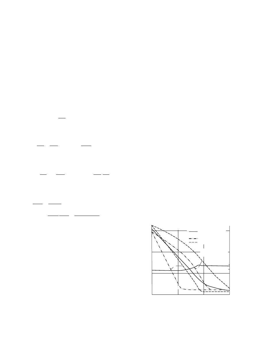
3. The alfa lfa bed is divide d into discrete layer s
along the he ight z , a nd within these layer s the
temperatur e T
k
and mate rial mois ture co ntent
X
k
are characteriz ed by lumped values .
4. In the discr ete layer s the airflow rate is divide d
proportio nally to the dr ying surfaces of the
componen ts.
5. The mixe d mean stat e of the air leavin g the
componen ts is regarde d as standar d for the
state of the air enterin g successive layer s (X
av
,
T
av
, enthal py).
The equ ation system descri bing the dryer mod el
for a given elem entary layer of the bed [25,125,1 31] is
as foll ows: moisture mass balance for the mate rial,
@ X
k
@t
¼ b
k
a
k
(X
k
X
e
,
k
) (13 : 47)
enthal py balance for the material ,
@ T
k
@t
¼
h
k
a
k
c
k
r
k
( T
a
T
k
)
b
k
a
k
r
c
k
( X
k
X
e
,
k
) (13 : 48)
moisture mass ba lance for the air,
@ x
k
@ z
¼ A
s
k
a
k
_
m
m
a
,
k
( x
e
,
k
x
k
)
A
a
j
k
_
m
m
a
,
k
@ x
k
@t
(13 : 49)
enthal py balance for the air,
@ T
a
,
k
@ z
¼
a
k
A
_
m
m
a
,
k
c
pa
[ s
k
(x
e
,
k
x
k
)c
pw
þ h
k
](T
k
T
a
)
A r
a
j
k
_
m
m
a
,
k
@ T
a
,
k
@t
þ
(1
j
k
) b
k
A r
k
_
m
m
a
,
k
c
p
,
a
(13 : 50)
equati on of de sorption isot herms ,
f ( X
e
,
k
,x
e
,
k
, T
a
,p
w
, p
b
)
¼ 0 (13 : 51)
The values of drying and mate rial characteris tics (s
k
,
b
k
, a
k
, b
k
, j
k
, c
k
, r
k
, and sorpti on isot herms ) in the
equati on system of the dryer model must be deter-
mined by e xperiment [132].
13.6.4 S
TRATEGY OF
S
OLUTION
Numer ical solution of the syst em of equ ations
above can be obtaine d by discr etiz ation in time
[25]. The main steps of the so lution process are as
follows :
1. Data input, calculati on of constant network
elements and charact eristic s
2. Selection of time step
3. Solution of the workin g model of the pro cess
control system on the basis of the initial stat e;
determinat ion of mod e of operati on
4. On the basis of the initial state T
(k)
, calcul ation
of the depen dent network elem ents an d charac-
teristics
5. Genera tion of the MFN models corres ponding
to the mode of ope ration
6. Solution of the MFN models for the subseque nt
period; determinat ion of _
m
m
F
(k
þ 1)
an d _
m
m
a
(k
þ 1)
,
for exampl e by the New ton–Rap hson method
7. Solution of therm al comp onent models on the
basis of _
m
m
F
(k
þ1)
, _
m
m
a
(k
þ1)
, and the initial state T
(k)
(for the collector, the finite time-element scheme
see Ref. [31]; for the storage, the finite difference
scheme can be applied); determination of the
temperature of air entering the dryer
8. Solution of the equations for the dryer by
applying an implicit finite difference scheme;
determination of material temperature and
moisture distribution in the bed
13.6.5 R
ESULTS OF
S
IMULATION
As an example, the results of simulation of the dryer
in
are present ed [25]: the thickne ss of
the fresh alfalfa layer in the bed, z
¼ 0.3 m; the
discretized layer thickness, Dz
¼ 0.075 m; time step
for collector Dt
c
*
¼ 0.5 h, for the dryer, Dt
d
¼ 0.1 h;
air mass flow rate density, _
m
m
a
¼ 0.171 kg/sm
2
. After
leaf wilting, _
m
m
c
(dry basis) for leaf is x
1
(0)
¼ 1.47 kg/
kg; for stem, x
2
(0)
¼ 1.62 kg/kg. Air inlet tempera-
ture T
a,in
as a function of time and the drying curves
are given in Figure 13.36. As can be seen from the
1.5
1.0
0.5
0.0
0.0
12.0
25
30
35
50
Material
T
a, in
T
a,in
(T )
⬚C
24.0
36.0
T.h
⫻
⫻
⫻
⫻
⫻
⫻
⫻
⫻
X, kg/kg
⫻
⫻ ⫻
II.
I.
Lucerne calculated
Lucerne measured
Leaf
Stalk
⫻ ⫻⫻
I
−Bottom layer
II.
−Top layer
X
a
= 10.5 · 10
−3
kg/kg
FIGURE 13.36 Drying curves of alfalfa.
ß
2006 by Taylor & Francis Group, LLC.

figure, the drying rates for the leaf and stem are
substa ntially different . In the top layer of the bed,
the stem reaches x
2
¼ 0.14 kg/kg moisture co ntent
in abou t 42 h. Under the cond itions given, drying can
be carried out in 2-d cycles .
13.7 DIRECTION AND CONTROL
OF SOLAR DRYERS
13.7.1 A
IMS OF THE
D
IRECTION AND
C
ONTROL
The direction and control of solar dryers aim to en-
sure the eco nomica l operati on of the dryer in ev ery
stage of the drying pro cess consider ing the actual state
of the material under dry ing as well as the actual
meteo rological conditi ons [177] .
13.7.1.1 Economy Aspects
The economic analysis of solar drying is presented in
. In this secti on economy aspect s are
interpreted in connection with the direction and con-
trol only. To fulfill the requirements of a good econ-
omy the savings should be increased and the costs
should be reduced.
Utilizing solar energy for drying is not simply a
method for saving conventional energy carriers but a
technology for producing dried materials of high qual-
ity. This aspect is especially important when drying
materials sensitive for quality deterioration. Products
serving human and animal foods are generally
very sensitive and their main characteristics (i.e.,
color, smell, taste, shape, nutritive, and other internal
substances) are highly dependent on the thermal and
sorption history of the material from the harvesting to
the preserved state and on the time interval of drying.
In Table 13.3 drying data are given for some agricul-
tural products. Cereal grains and grain legumes need
to be dried from an initial moisture content of about
30% (wet basis) at harvest to a level of 12%. Leafy
green vegetables and fruits have an initial moisture
content of about 60–80% to be reduced to the range
of 10–25% for safe storage. Safe drying air temperat-
ures are of 35–608C and for some products these
temperatures are higher at the end phase of the drying.
The quality of the dried products has an effect on
the economy by influencing the marketing capability
and income of the products because a higher price can
be achieved by better quality. To ensure the required
preconditions for drying of such sensitive materials a
technological direction and process control is needed.
The loss in quality of the dried product should be
considered as a saving of negative value [176].
One of the main components of savings for semi-
artificial and solar-assisted dryers is the price of the
conventional energy carriers substituted by solar en-
ergy. It should be emphasized that the solar energy
utilized by the solar dryer is not equal to the energy
collected by the solar collector and transferred into
the drying air but the energy effectively used in the
drying process. The energy effectiveness of solar
dryers depends also on the exit energy losses, which
can be reduced by applying a proper direction and
control strategy. In the case when the energy effect-
iveness of a given solar dryer is lower than that of a
TABLE 13.3
Drying Data for Some Agricultural Products
Product
Moisture Percent (wb)
Drying Air
Temperature (8C)
Initial
Final
Bananas
80
15
70
Barley
18–20
11–13
40–82
Beets
75–85
10–14
—
Cardamom
80
10
45–50
Cassava
62
17
70
Chilies
90
20
35–40
Coffee seeds
65
11
45–50
Copra
75
5
35–40
Corn
28–32
10–13
43–82
Cotton
25–35
5–7
—
French beans
70
5
75
Garlic
80
4
55
Grapes
74–78
18
50–60
Green forages
80–90
10–14
Hay
30–60
12–16
35–45
Longan
75
20
Medicinal plants
85
11
35–50
Oats
20–25
12–13
43–82
Onions
80–85
8
50
Peanuts
45–50
13
35
Pepper
80
10
55
Potato
75–85
10–14
70
Pyrethrum
70
10–13
Rice
25
12
43
Rye
16–20
11–13
Sorghum
30–35
10–13
43–82
Soybeans
20–25
11
61–67
Spinach leaves
80
10
Sweet potato
75
7
75
Tea
75
5
50
a
Virginia tobacco
85
12
35–70
Wheat
18–20
11–14
43–82
a
At the end of drying, for 2–3 h 1008C.
Source: From Mahapatra, A.K. and Imre, L., Int. J. Ambient
Energy, 10(3), 163, 1989.
ß
2006 by Taylor & Francis Group, LLC.

conventional one a negative value in savings should
also be considered.
The possible savings and the investment and
maintenance costs of solar dryers are interdependent.
Well-directed solar dryers need higher costs. Inexpen-
sive, simple, and unsophisticated solar dryers, gener-
ally, have no appropriate devices for direction and
control. These types of solar dryers are of great im-
portance first of all for country use, for substituting
open-air drying of nonsensitive materials and elimin-
ating the well-known disadvantages of natural drying.
Solar dryers of high performance or for drying of
quality-sensitive materials should be well directed. The
higher investment and maintenance costs can be bal-
anced by the better quality of the dried product and by
the longer annual operation time. The annual oper-
ation time can be extended when drying materials of
long growing time and several harvests in a year (e.g.,
meadow grass, alfalfa) or in cases of solar dryers ap-
plicable for drying of various materials having differ-
ing ripening times, one after the other (e.g., herbs,
medicinal plants, spices and aromatic plants, seeds).
Another way for year-round utilization is the multi-
purpose application of the solar energy converter of
the dryer when, in the idle periods of drying, the solar
energy collected is utilized for other technological pur-
poses (e.g., for satisfying technological hot water de-
mands of an agricultural farm). These complex
systems should have appropriate direction and control
devices to realize an economical operation strategy.
13.7.1.2 Strategy of Direction
The strategy of the direction should be elaborated by
taking into consideration the drying characteristics of
the material and the regulation possibilities of the solar
dryer to be used. In the knowledge of the drying char-
acteristics of the materials to be dried (i.e., sorption
isotherms, drying curves) the appropriate schedule of
the drying operation should be elaborated and, using it
as a basis, the possible methods for interventions should
be determined. Even in case of the most simple solar
dryers some methods in the direction are recommended.
13.7.2 D
IRECTION AND
C
ONTROL
A
CTIONS
13.7.2.1 Direction of Drying Operation
Direction includes actions that are required for the real-
ization of an appropriate drying process in the dryer
(i.e., to follow with attention the actual state of the
material under drying) and determine and execute the
necessary interactions by applying a direction strategy.
The first phase of the drying to be directed is the
feeding of fresh material into the dryer. It should be
emphasized that the good quality of the fresh material is
a precondition of the good quality of the dried product.
This action should be in harmony with the ripening
state of the material and the point of views of the drying
should be asserted in the harvesting technology.
The main direction actions of the drying process
can be summarized as follows:
1. Feeding fresh material into the dryer
2. Turning or tedding the layer of the material
under drying occasionally in the case of un-
sophisticated (e.g., tent type) dryers
3. Regulating the airflow rate
4. Regulating the recirculation of the air
5. Regulating the intermittent drying process
(determining the beginning and the interval
of the break)
6. Separating the solar dryer from the atmos-
phere in the night and in rainy weather when
no auxiliary energy source exists
7. Regulating the operation of the auxiliary
energy source
8. Distribution of solar energy collected inside
the drying space and between the cells in the
case of multicell solar dryers
9. Determining the mode of operation in the case
of complex and multipurpose solar dryers and
ensuring the optimal distribution of solar
energy collected between the dryer, the stor-
age, and the other heat consumers
10. Regulating the operation of storage in the
case of solar dryers with heat storage
11. Determining the appropriate inlet tempera-
ture of the drying air in the different stages
of the drying process
13.7.2.2 Control of Drying Operation
Control actions of the drying operation are concerned
with holding the given values of some operational
parameters determined by the direction strategy.
The main control actions are as follows:
1. Temperature control of working mediums
2. Relative humidity control
3. Mass flow rate control of flowing mediums
4. Switch in and out devices (e.g., fans, humidi-
fiers, valves or dampers, auxiliary heaters)
when the limit values of some parameters occur
5. Control of charging the thermal storage of the
system
6. Control of the rate of drying
7. Control of the recirculation
8. Control of the intermittent drying process
ß
2006 by Taylor & Francis Group, LLC.

13.7.3 P
RINCIPLES OF THE
D
IRECTION
13.7.3 .1 Di rection Strategy of Static
Be d Solar Dryers
For the drying pro cess with forced convecti on in
a static bed, the static be d is gen erally arrange d in a
drying ch amber and the heat is trans ferre d from the
drying med ium to the mate rial by convecti on. In
through- flow dryers air is led below the layer and
flows upwar d through the bed.
The state of the mate rial to be dried in a static bed
can be approxim ately ch aracterize d by the change of
state of the drying air flowi ng through the bed. The
change of state of the air can be foll owed in the
enthal py (h) and ab solute mois ture co ntent ( x) chart
of M ollier.
In Figure 13.37 the h
x diagram for an ope n-cycle
drying process is present ed. The actual state of the
atmosp heric air is rep resented by 0. Suppos ing that
the mass flow rate of the air is _
m
m , he at flux into the
air is f
h
, the tempe ratur e increase of the air can be
calcula ted:
Dt
¼ t
1
t
0
¼
f
h
c
p
_
m
m
(13 : 52)
where c
p
is the specific he at capacit y of the air. The
tempe rature of the air entering the dryer is t
1
. Sup-
posing furt her that the drying by convecti on is nearly
adiabat ic, the change of stat e of the air in the be d is
approxim ately of h
1
¼ const. The air will approxi-
mate the equ ilibrium relat ive hum idity U
e
of the ma-
terial and the absolut e mois ture con tent of the air will
increa se by Dx (in Figu re 13.37, point 2). The mass
flow rate of evap oration N from the mate rial can be
express ed indirectl y:
N
¼ _
m
mD x (13 : 53)
and the energy flux practicall y con sumed for drying is
f
D
¼ _
m
m Dxr
¼ Nr (13 : 54)
where r is the total hea t of evap oration of the wat er
from the material under drying. The f
D
value can
also be expressed by the temperature difference of
the air:
f
D
¼ _
m
mc
p
(t
1
t
2
)
(13:55)
When the material to be dried has a quasiconstant
rate period between the initial integral moisture con-
tent W
0
and the first critical moisture content W
cr,1
the drying rate curve N(W) has the shape given in
Figure 13.38. In the figure the temperature curve t(W)
is also given. In the constant rate period the tempera-
ture of the material approximates the wet bulb tem-
perature t
wb
and remains practically constant (t
m
ffi
t
wb
¼ const). In the falling rate period the tempera-
ture of the material will approximate the dry bulb
temperature t
1
.
The moisture distribution in the bed of a thickness
Dz
can qualitatively be characterized by the curves in
given for the diff erent stage s of drying.
For time t
¼ t
1
from the beginning, the upper layer
of the bed above point 1 is almost of the initial
moisture content. Drying of the surface layer starts
at time t
¼ t
2
and will be continued with approxi-
mately constant rate until the moisture content of the
surface layer will be reduced to the first critical (W
cr,t
)
value t
¼ t
3
. In time interval t < t
3
, f
D
remains
U
1
1
0
2
2
*
U
e
U
2
*
U
=
1
h
t
t
1
t
o
h
o
Δ
x
x
o
x
2
x
t
2
h
1
=
const.
t
2
*
FIGURE 13.37 Change of state of the air in an open-cycle
drying process in h–x chart.
N
t
t
1
t
wb
W
e,1
W
end
W
cr,1
W
o
K
1
W
N(W )
t(W )
FIGURE 13.38 Typical drying rate and temperature curves
of materials having constant drying rate period.
ß
2006 by Taylor & Francis Group, LLC.
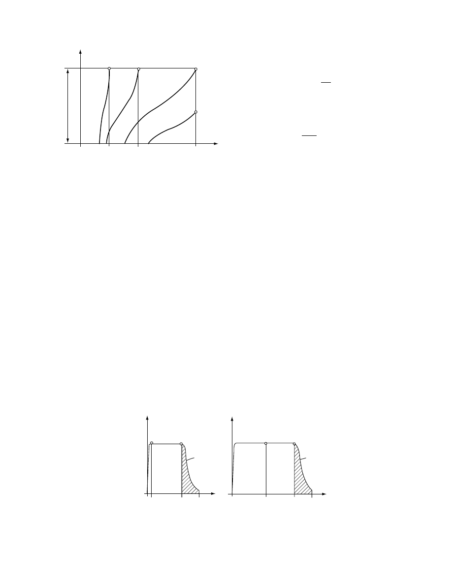
practicall y constant , not c onsider ing a short star ting
period. W hen t > t
3
(i.e., in the falling rate period of
drying) , t
m
an d t
2
will increa se t
2
! t
2
x
x
) an d, accordi ng to
, the exit
energy loss of the dr yer f
L
¼ _
m
mc
p
( t
2
x
t
2
) will in-
crease . Because of the increa sing energy loss the ef-
fectivenes s of the dryer wi ll success ively decreas e in
the fall ing rate period ( t
3
< t < t
4
).
13.7.3 .2 Di rection of Opera tion of Static
Be d Dryers
Consid ering the dry ing process in a static bed de -
scribed qua litatively be fore, conclusio ns for the direc-
tion can be summ arize d as foll ows.
1. In Figure 13.40 the f
D
(t ) function is presen ted
at con stant inlet parame ters t
1
, U
1
for tw o diff er-
ent be d thickne sses. In the case of a thin bed (Fig-
ure 13 .40a) t
2
is almos t negli gible (for t
2
see also
Figure 13 .39), t
3
t
2
is the tim e inter val of the prac-
tically constant rate period, t
4
t
3
is that of the fall ing
rate period. By increa sing the thickne ss of the bed
t
2
wi ll increase, t
3
t
2
and t
4
t
2
intervals remain
practicall y constant (Figur e 13.40b) . The energy
effecti veness of the dryer (taki ng f
h
a s con stant)
e
¼
f
D
f
h
(13 : 56)
is the functi on of the tim e. For the time inter val of
drying t
4
the average va lue of e is
e
av
¼
1
t
4
f
h
ð
t
4
0
f
D
( t ) dt (13 : 57)
The e
av
can be increa sed by increa sing the thickne ss of
the be d (see the ratio of the da rk and whi te areas of
Figure 13.40a and Figu re 13.40b) .
2. Though by increasing the layer thickne ss the
energy effecti veness of the dryer c an be improved ,
another effe ct has also to be taken into consider ation.
Since the time inter val t
2
wi ll be longer, this method is
not advan tageous for mate rials sensi tive to quality
deteriorat ion because the loss of inter nal sub stance s
is directly pro portion al to the time passed from the
harvesting to the preser ved stat e. For the mate rial
situated in the upper layer of the bed, drying will
start after a lon ger tim e an d some deteri oration may
occur. To solve this con tradictio n in the economy
requir ements, drying should be started with a fair ly
thin layer thickne ss. The thickne ss of the be d should
be increa sed from tim e to time by feedi ng success ively
a new fresh layer in at t
¼ t
3
. Thi s multila yer feeding
method can be ap plied when the harvest ing can also
be fulfil led success ively (e.g ., in case of drying
meadow grass or alfa lfa in a solar drying- storing
barn). In this case the task of the direction is to
determine the time points of t
3
. Obser vation of t
3
is
possible with a fairly good approxim ation by meas-
uring continuously the temperature t
2
and the relative
humidity U
2
of the air leaving the bed.
3. Exit energy loss can be reduced by the multi-
layer feeding also in case of materials not having a
Z
4
3
2
1
W
e,1
W
cr,1
W
end
W
o
W
ΔZ
t
4
t
3
t
2
t
FIGURE 13.39 Moisture distribution in a static bed at the
different stages of drying.
2
f
D
f
D
f
D
(
t)
f
D
(
t)
t
2
t
3
t
4
t
t
2
t
3
t
4
t
3
2
3
(a)
(b)
FIGURE 13.40 Energy flux consumed for drying in the function of time: (a) thin bed; (b) increased bed.
ß
2006 by Taylor & Francis Group, LLC.
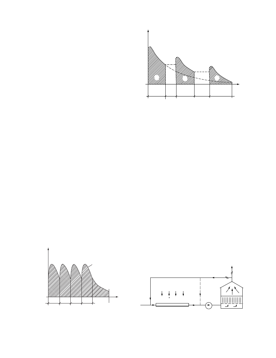
constant drying rate period at all. As it can be seen
from Figu re 13.41, by feedi ng new layers in a fter the
time inter vals of Dt , the value of e
av
will be much
higher than that of the single process es fulfilled one
after the oth er.
4. Anothe r wel l-known direction method is the
applic ation of intermittent operati on in the falling
rate period of drying (Figur e 13.42). The first dry ing
interval of Dt
1d
is foll owed by a break of Dt
1b
and
so on ( Dt
d
Dt
b
, . . . ). During the break the uneven
moisture dist ribution inside the mate rial tend s to
equali ze and, in the next drying interval, the dry ing
rate will be higher again. This way e
av
can be in-
crease d and the electrica l energy consu med for driv-
ing and fan can be reduced. To find the be st
combinat ions of the drying pe riods an d the breaks,
an optimizat ion problem ha s to be solved. For opti-
mization the drying cu rves of the mate rial, the time
functio n of the internal moisture equali zation pro cess
at diff erent integ ral moisture content s, and the tech-
nical data of the dryer itself are needed. The direction
strategy can be elabora ted by computer sim ulation
and proved by experi ments .
For solar dryers not having any heat stora ge the
utilizat ion of the solar energy collected in the break s
is a pro blem. One possibi lity is to time the break
intervals in the night. This co ndition in some cases
will not permi t fulfillme nt of the optim al stra tegy.
5. Anothe r possibi lity is to divide the drying space
into individu al ce lls (
). Eac h cell
should have its own fan an d the constr uction shou ld
permit the distribut ion of the solar energy collec ted
between the cell s in an optional rati o. The inter mit-
tent drying pro cesses in the diff erent cells are shif ted
in tim e, making it possible to utilize more solar en ergy
in one cell, whereas in another cell a break is in
progres s.
6. In the falling rate period of drying, the energy
effecti veness of the solar dryer can be impr oved by
recirculat ing one part of the air leaving the material .
This well-k nown method can be recomm ended, first
of all, for drying mate rials of lon g drying time.
A sim plified scheme of a solar dryer having a
separate d collector is present ed in Figure 13.43. Par t
of the recir culated air can be regula ted by valves 4
moving togeth er bui lt in the air duc ts servi ng for the
outlet air 5 and for the recirculat ing air 6. Airflo w of
the air duct 6 is mixed with fres h air be fore entering
the collec tor 1. The mixe d air will be preheat ed in the
collector an d transp orted by the fan 2 to the drying
chamber 3. The recirculat ed air can also be mixe d
with the fres h air preheat ed by the collector be fore
the fan (dott ed line 6*).
The princi ples of the direct ion can be foll owed in
an h
x diagra m (
). The state of the fresh
air is represented by 0, the air preheated in the col-
lector (without recirculation) by 1 and, the state of the
air leaving the dryer by 2. In case of applying recir-
culation in a proportion of (b/a) _
m
m, the state of the
mixed air will be of M. Flowing through the collector
the air will be preheated to t
1
* (point 1*). Supposing
that the temperature of the material is t
2
(point 2
f
D
Δt
Δt
Δt
Δt
t
t
4
f
D
(
t)
FIGURE 13.41 f
D
(t) function with multifeeding in for dry-
ing materials not having any constant rate period.
f
D
Δτ
1d
Δτ
1b
Δτ
2d
Δτ
2b
Δτ
3d
τ
1
2
3
FIGURE 13.42 f
D
(T) function for intermittent operation.
6
1
2
6*
3
4
5
FIGURE 13.43 Simplified scheme of a solar dryer with
recirculation.
ß
2006 by Taylor & Francis Group, LLC.

repres ents the state of air in equ ilibrium with the
material ), the direction of the change of stat e of the
air wi ll be of 1*2. As a resul t of the increa sed vapo r
pressur e of the air (p
vl
* ) the rate of drying will tem-
porari ly be de creased and the tempe ratur e of the
material wi ll increa se. The state of the air leaving
the mate rial will tend to 2*.
App lying recir culation the mate rial can be hea ted
to a higher temperatur e level than that withou t recir -
culation , wher e the rate of drying will be higher. The
operati on can be direct ed by regulating the b/ a rati o.
In the co urse of drying, tempe ratur e of the material
tends towa rd 1*. This fact has to be consider ed when
regula ting the recirculat ion.
In the case when the recir culat ed air is mixed wi th
the air leavi ng the colle ctor (see duct 6* in
) the airflow rate in the collector will de crease
and the tempe ratur e t
1
* wi ll increa se. Air tempe ra-
ture dep ends on the b/a ratio (see Figu re 13.45) . The
mixing point M will repres ent the state of the air
entering the dryer and it will be situ ated betw een 1*
and 2. The pos ition of M will chan ge in the fun ction
of the material tempe ratur e (2 tends to 2*). The pos -
sibilities for drying will be sim ilar to the previous
version . In bot h cases the energy effecti veness of the
dryer wi ll be higher in spite of the great er hea t losse s
in the colle ctor and the drying ch amber. A disadva n-
tage of this syst em is the addition al cost of the air
duct 6. By applyin g a special constru ction duct 6 can
be e liminated . As an example the solar timber drye r
present ed in
The direct ion of the operation of such a dryer is,
princip ally, the same as that written be fore. Repre -
senting the process in a n h–x diagram, some differ-
ences aro se from the facts that the stack is pa rtially
irradiat ed by the absorber and the airflow co ntacts a
differi ng area of the absorber surfa ce before entering
the stack. To e laborate the direct ion stra tegy of solar
dryers operati ng by recirc ulation, exp eriments are
recomm ended.
13.7.3 .3 Direct ion of Solar Dry ers with
Heat Tr ansfer by Conve ction
an d Direct Irrad iation
, a simp lified sch eme of a solar tunn el
dryer ope rating with convecti on and direct irra diation
[184,203] is present ed. A single-cove red solar colle ctor
having a transp arent coveri ng is con nected to the
drying space. In the drying space the mate rial to be
dried is arrange d in a fairly thin layer an d, through
the trans parent coveri ng, it is direct ly irra diated. Dry-
ing air is transpo rted through the co llector an d the
drying space by a fan. In rural areas the fan can be
driven by the elect ricity pro duced with phot ovolta ic
modules [226].
The operati on of the dryer can be foll owed in an
h–x psych rometric chart (Figur e 1 3.46b). In the col-
lector the atmosp heric air is he ated to the drying
tempe rature t
1
. In the drying space tempe rature t
1
is
approxim ately constant if the heat deman d of evap -
oration is satisfied by direct irrad iation. The state of
the air leaving the dryer is repres ented by point 2. The
rate of drying is N
¼ _
m
mD x, wher e _
m
m is the mass
flow rate of the air. Durin g the sun ny hour s of the
day the state of the atmos pheric a ir is 0 a nd the solar
irradiat ion is changing ov er time. As a consequen ce,
t
1
and t
2
temperatures are also varying. Neverthe-
less, the character of the change of state process of
the drying air can be represented by the line 012 in
Figure 13.46b.
Let us suppose that the temperature of the mater-
ial—and of the air in equilibrium with it—is t
2
when,
in the evening, the solar irradiation stops. If the fan
h
h
1
h
0
x
0
x
M
x
2
P
v
M
U
=
1
x
x
∗
2
P
∗
v1
2
∗
2
1∗
P
v1
O
1
a
b
FIGURE 13.44 Change of state of the air with recirculation
and mixing before the collector.
h
O
1
1
∗
2
∗
M
∗
M
2
∗
x
0
x
∗
M
x
∗
2
x
U
=
1
FIGURE 13.45 Recirculation with mixing after the collector.
ß
2006 by Taylor & Francis Group, LLC.
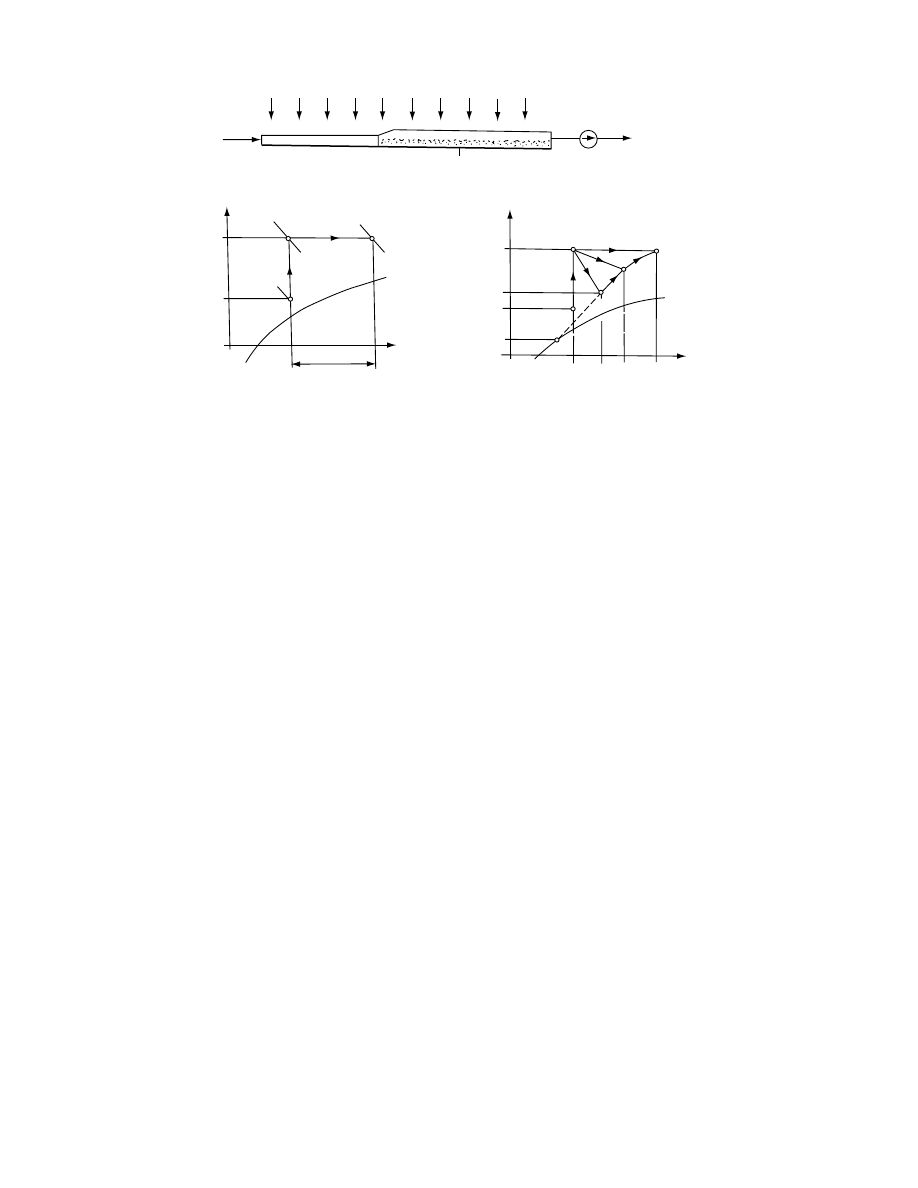
will be stopped, too, the material having a higher
partial vapor pressure will keep evaporating. Without
ventilation the water evaporated from the material
will partially condense on the internal surface of the
covering. In the night the atmospheric temperature
will decrease (t
0
x
, see Figure 13.46c) and the covering
will cool down by convection and radiation. To avoid
the condensation and the possible damage to the
quality of the wet material it may seem to be advis-
able—at least in the first stage of drying—to keep the
fan in operation also in the night. As a consequence of
the evaporation and of the cooling effects the tem-
perature of the material will decrease. If the tempera-
ture decreases below the atmospheric temperature
that existed in daytime (t
2
x
< t
0
), next morning the
partial vapor pressure of the preheated air will be
higher than that of the material and, for a time inter-
val, the material will absorb some water vapor from
the air (rewetting effect). The temperature of the ma-
terial will increase by the convective heat transfer
from the air as well as by the direct irradiation of
the sun (from t
2
x
to t
2
).
13.7.2.2.1 Possible Methods for Direction
During drying, the rate of evaporation on the surface
of the layer will be higher than that in the bottom of
the layer. In the falling rate period the temperature
of the surface layer will increase over the tempera-
ture of the air stepping in the drying space from the
collector. Heat transfer from the surface into the layer
will increase and, at the same time, a part of the
energy gained by direct radiation will be transferred
into the air by convection. As a consequence, the
energy effectiveness of the dryer will decrease. The
disadvantageous effects can be avoided by turning
the layer over from time to time. This operation
needs some handwork and can be applied only for
materials not sensitive to the mechanical effects of
turning or mixing. Without turning, the overheating
of the surface should be prevented by the appropriate
design of the dryer.
In the night, the cooling down effects can be mod-
erated by reducing the mass flow rate of the air. It can
be realized by a throttling or by using a driving motor
of variable speed. Heat losses can be reduced by
shading the transparent covering. A further pos-
sibility is the application of a solar collector with
heat storage. A heat storage pebble bed or latent heat
storage can be used. The surface of the storage
layer may serve as absorber. Application of heat stor-
age results in more sophisticated construction and
higher investment costs. Economy aspects should be
determined in each case separately.
13.7.3.4 Direction of the Operation of Tent,
Greenhouse, and Cabinet-Type
Solar Dryers
Tent, greenhouse, and cabinet-type dryers have sim-
ple and unsophisticated structure. The material to be
dried is partially or totally irradiated during drying.
Problems that may arise during the operation of such
dryers are similar to those discussed in the previous
section. The possible means of direction of the oper-
ation are also the same: turning the material over
from time to time and to close and shadow the drying
space during the night or, in some cases, to reduce the
airflow in night operation.
Air in
Solar collector
(a)
(b)
(c)
Directly irradiated
drying space
Fan
Air
out
h
0
1
2
0
0*
2
x
2
xx
1
2
U
=
1
U
=
1
t
1
h
1
h
0
h
2
t
0
t
0
t
0
x
t
2
x
x
0
x
0
x
2
x
2
x
x
Δx
t
h
t
1
t
FIGURE 13.46 Solar dryer with heat transfer by convection and direct irradiation: (a) simplified scheme of the dryer; (b)
change of state of the air in h–x chart; (c) night operation.
ß
2006 by Taylor & Francis Group, LLC.

In Figure 13.47 a scheme of a cabinet -type dry er
for hous ehold use is presen ted to dry fruits, herbs,
and ve getables. Mater ial to be dried is arrange d in a
thin layer on a tray 1 with perfor ated bottom inside
the cabinet 2 wi th a singl e glass coveri ng 3. The air is
introd uced to the dryer by free con vection using a
black- painted meta l sheet 4 of the same surface area.
The meta l sheet serves as a secon dary uncovered
collector by increasing the inlet air tempe ratur e. The
airflow can be con trolled by the throt tling device 5 at
the air outlet . During the day the posit ion of the
dryer can be changed accordi ng to the pos ition of
the sun. At the first stage of the dry ing the sli der 5 is
open. The outlet cross- section al area of the air shou ld
be de creased accordi ng to the progres s of the dry ing
process . Thus , the airflow rate will also be decreas ed
and the tempe rature of the air increa sed. In the night,
the mate rial sh ould be shaded by posing the black-
painte d sheet 4 on the transp arent co vering of the
cabinet 2 and ha ving the slider 5 closed.
13.7.3 .5 Di rection of the Opera tion
of Chimne y-Typ e So lar Dryers
In chimney -type solar dryers the driving force of the
airflow is the hydro static pressur e diffe rence caused
by the decreas ing densit y of the preh eated air (chim -
ney effect) . Since no conven tional energy sources a re
needed , chimney -type solar dryers can effecti vely be
used as coun try dryers. For ke eping the airflow on in
the night, ch imney-ty pe dryers usuall y ha ve some
kind of he at stora ge.
, the constr uction of a chimney -type
solar dryer [6] is pr esented . Duri ng night ope ration
the trans parent walls 6 can be insul ated by reflecting
panels. The air duct of the c ollector shou ld be closed
and air duc ts [5] below the drying ch amber shou ld be
opened . The atmos pheric air wi ll be prehe ated by
convecti on when flowing through the heat storage
space and contact ing wi th the water contai ners.
Ano ther con struction is present ed in Figure 13.48
[178,214] . This dryer ha s a colle ctor 2 wi th a late nt
heat storage mate rial (C aCl
2
6H
2
O) as ab sorber 4.
Two additio nal late nt heat stora ge plate s a re ap plied
[5] that are pulled out from the coveri ng of the col-
lector and are directly irra diated in dayti me. The
souther n walls, includi ng the wall of the chimney ,
are mad e of trans parent mate rial; the nor thern wal l
and the bottom 6 are insul ated. The mate rial to be
dried is arrange d on trays 7 in the drying chamb er 1
and partially irradiated. On the northern wall of the
chimney 3 a layer of latent heat storage is built in 4
that produces additional preheating effects for the air
in night operation.
As to direction of the operation the latent heat
plates 5 should be pushed below the covering of the
collector for night operation (see the figure). Since the
heat storers are directly irradiated, they can be
charged to a higher temperature level than they
could be when heating by the air. The airflow through
such dryers can be assisted by a windmill driving a fan
built in the chimney.
Air out
5
1
3
2
Air in
4
FIGURE 13.47 Scheme of a solar cabinet dryer for household use.
Transparent
Air
out
Air
in
5
2
4
6
6
7
1
3
4
FIGURE 13.48 Simplified scheme of a chimney-type solar
dryer with latent heat storage.
ß
2006 by Taylor & Francis Group, LLC.

13.7.4 B
ASIC
P
RINCIPLES OF
C
ONTROL
13.7.4.1 Application of Automatic Control
13.7.4.1.1 Economy Aspects
Values of the operational parameters required by the
direction strategy can be effected automatically by
using controllers. Application of automatic control
can be justified by the possible reduction of workforce
as well as by the higher reliability compared to
manual control. Though the instrument cost is high,
its effect on economics can be balanced by the better
quality, by the better energy effectiveness, and, in case
of sophisticated solar dryers of high performance, by
the improved security of the drying operation. Econ-
omy analysis has to be done in each case separately.
13.7.4.1.2 Aspects for Designing the Control
Control systems generally consist of three main elem-
ents. A sensing element (sensor) is used for measuring
the actual value of the parameter to be controlled.
The control device serves for forming commands for
intervention, if necessary. The element for interven-
tion (e.g., a motoric valve) executes the command of
the controller.
Process control systems generally operate with a
constant set point. It should be emphasized that exact
control is not always necessary and overinstrumenta-
tion should be avoided. Solar dryers generally have
some parts of large capacities that reduce the effects
of disturbances.
For the accurate design of the control system a
detailed operational analysis is needed. The require-
ments for the design can be determined on the basis of
the information produced by the analysis. In simple
cases, the appropriate controller can be selected by
using rules of thumb. Solar dryers having various
input parameters can often be controlled by individ-
ual controllers. In cases when the control aims at
optimizing the drying operation, commands for inter-
ventions should be formed by considering several
input and output variables. For this purpose a micro-
processing control device can be applied.
The detailed description of process control theory
is beyond the scope of this chapter. In actual design-
ing problems a consultation with experts in process
control is recommended. A brief overview of the main
types of controllers is offered here (for further details,
see Refs. [179–181]).
13.7.4.1.3 Main Types of Control Systems
On–off control is the most simple and the cheapest
method and it is widely used. If the value of the meas-
ured variable is less than the set point value, the con-
troller is on. The output signal of the controller is a
given value. When the measured variable is above the
set point, the controller is off. In solar dryers on–off
temperature controllers are used (e.g., for control of
the operation of auxiliary heaters in a water storage
tank). A disadvantage of this control system may be
the uncertain operation and, actually, some overshoot
may occur.
Closed-loop or feedback control systems operate
by adjusting automatically one of the input variables
of the process by comparing a signal fed back from
the output of the process with a reference input. The
difference serves as signal for the controller. The sys-
tem can be characterized by the transient response of
the output of the process due to some specific vari-
ations in the input. The change in input may be either
a change in the set point or in one of the load vari-
ables (e.g., uncontrolled flows and temperatures).
Two different operations can be realized. With servo
operation the aim is to follow changes in the set point.
With regulator operation the output of the process
should be kept constant in spite of some changes in
load variables.
Open-loop control systems are used when every
input variable of the process should be constant.
Open-loop control can effectively be used when a
closed control is not needed, when the change in
inputs is not strong, or in cases when the feedback
control is not good enough. The open-loop control is
called feed-forward control when one of the input
variables is measured and used for adjusting another
input variable.
13.7.4.1.4 Main Types of Control Actions
In Figure 13.49, a block scheme of a control system is
presented. In the case when the set point value x
0
is
constant the control is called value keeping. If the set
point is a function of time, that is, x
0
(t), a signal is
needed for operating the set point device. Various
principles can be used to form commands for inter-
ventions by the controller. The basis of the methods is
the error e, which is the difference between the con-
trolled parameter (control signal x
c
) and the set point
Sensor
Set point
device
Signal
forming
Amplifier
Controller
Comparing
Control
signal
Xc(T )
X0(T )
e (T )
Xv
Xl
FIGURE 13.49 Block scheme of a control system.
ß
2006 by Taylor & Francis Group, LLC.
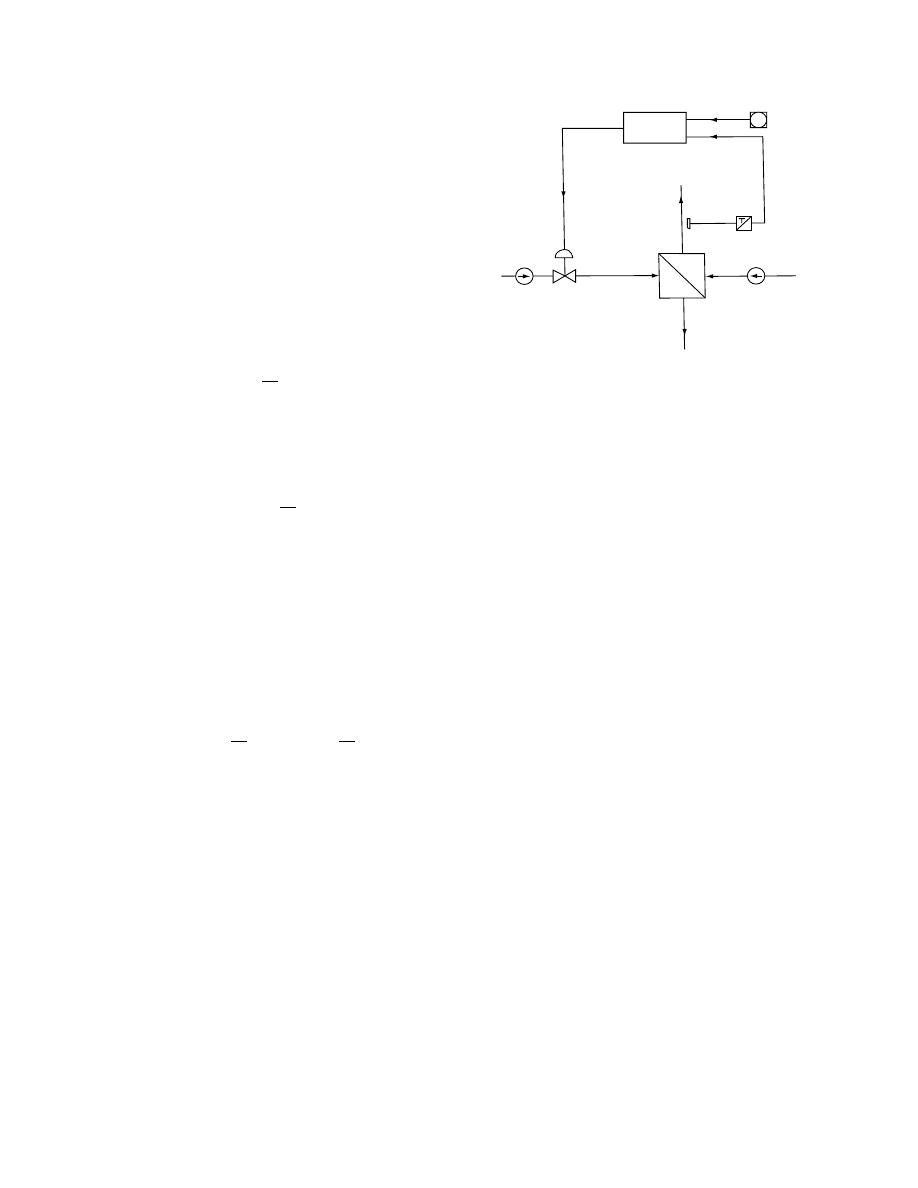
x
0
: e
¼ x
0
x
c
. Controllers have a signal-forming unit
that produces the command signal as output x
i
.
The proportional controller (P) produces its out-
put proportional to the error
x
i
¼ K=x
0
x
c
=
¼ Ke
(13:58)
where K is the gain of the controller. At a given
working point, the change in the output related to a
differential change in input is called the gain of the
controller.
With integral control (I) output of the controller is
proportional to the time integral average value of the
error
x
i
¼
1
t
R
ð
t
R
0
e dt
(13:59)
where t
R
is the reset time.
The two-mode proportional integral (PI) control-
ler produces its output by addition:
x
i
¼ K e þ
1
t
R
ð
t
R
0
e dt
(13:60)
Derivative control action (D) can improve the re-
sponse of slow systems when coupling parallel to
proportional control by adding an effect proportional
to the time derivative of the error. This way some
disadvantageous effects of large load changes and
the maximum error can be reduced.
The three-mode controller has a proportional and
an integral character with derivative action (PID).
The output signal of a PID controller is
x
i
¼ Ke þ
1
t
R
ð
t
R
0
e dt
þ t
D
de
dt
(13:61)
where t
D
is the derivative time.
The output signal x
i
of the signal-forming unit will
be amplified and modified. The output of the control-
ler is the signal for intervention x
v
. As an example the
scheme of the automatic temperature control of a
liquid–air heat exchanger is given in Figure 13.50.
13.7.4.1.5 Selection of Control Systems
In the operation of control systems stability is re-
quired. Operation is stable when continuous cycling
will not occur. Instability could be the consequence of
the increase in the overall gain of the controller above
a maximum value. The overall gain of the controller is
the product of gain terms in a closed loop. The role of
the time lag may also be considered. Different stabil-
ity criteria have been elaborated and various rules
developed. Integral control and derivative control
action can improve the stability of systems added to
proportional control. The final performance of a sys-
tem is affected by the characteristics of the process to
be controlled, by the operational characteristics of the
controller used, and by the nature of the disturbances
to be expected.
Operational characteristics can be described by
the response function of the system x(t) to a step
change in load. The system consists of the process to
be controlled and of the controller. The mathematical
relationship between input and output is called a
transfer function. The time t
c
necessary to approxi-
mate the required value within a given difference Dx
(mostly, Dx
¼ + 0,02...0,05) is called control time.
The response function of the controlled process (not
having any integrating character) can be character-
ized by the time lag t
1
and by the time constant t
t
.
For the selection of the appropriate control system a
dynamic analysis is needed that can inform the designer
about the type of controllers really needed. Some
general recommendations follow. In cases when the
expected disturbances are strong and the control time
permitted is long enough, proportional (P) controller
can be used. PI controllers can be applied with t
c
t
1
>
6.
PID controllers are recommended in the range of 4 t
1
<
t
c
<
6. For flow rate control and for level control P and
PI controllers are used; for temperature control, P, PI,
and PID controllers are mostly applied.
13.7.4.2 Control of Solar Dryer Operating with
Recirculation
With solar dryers of multicell construction the col-
lector field serves for more than one drying chamber.
Recirculation of the drying air can be directed for
keeping the inlet air temperature constant. The solar
energy saved by recirculation can be utilized for
Command
signal
for
intervention
X
i
Controller
Set point
Control
signal
X
c
Fan
Air
in
Air
out
Liquid
out
Pump Control
valve
Heating
liquid in
Heat exchanger
Temperature
sensor
X
0
FIGURE 13.50 Control scheme of a liquid–air heat exchanger.
ß
2006 by Taylor & Francis Group, LLC.
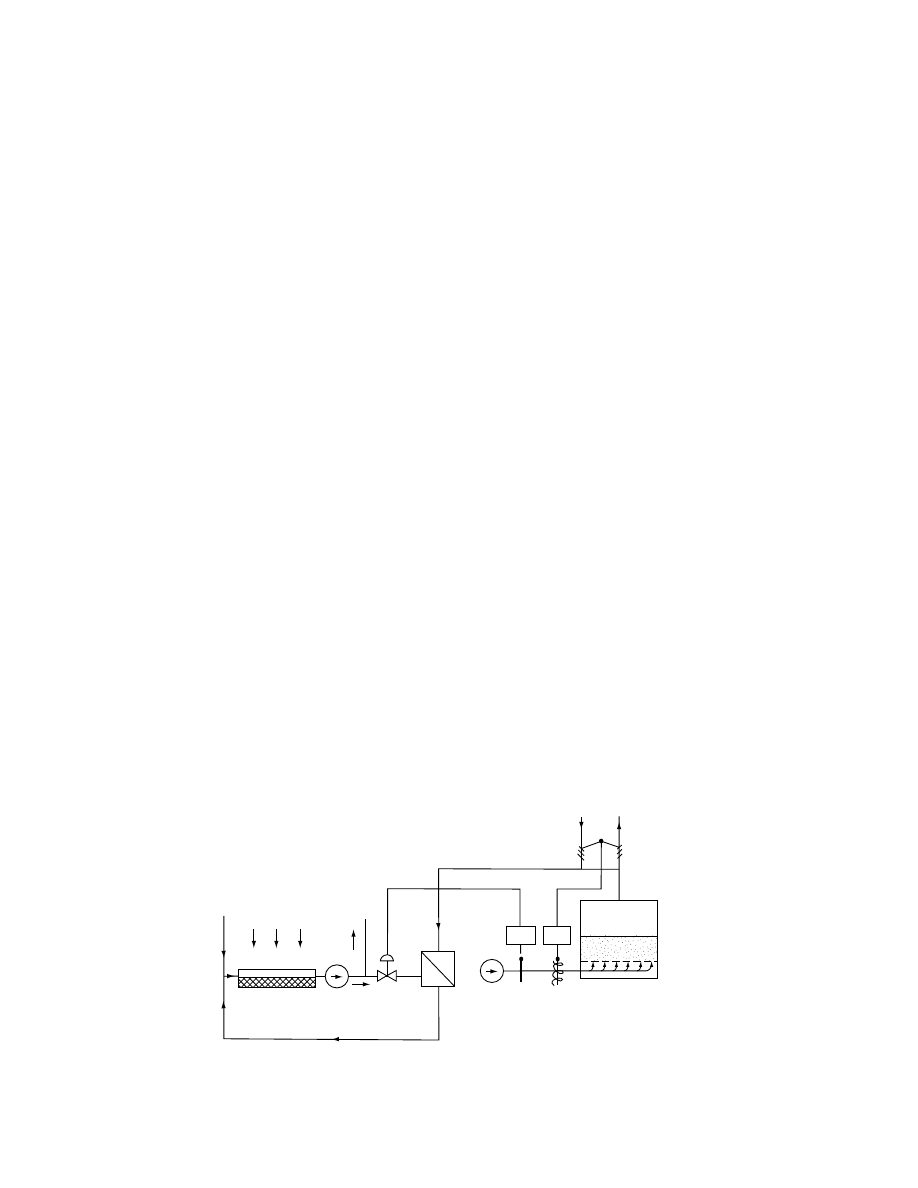
preheat ing the air of an other drying chamber (or for
other technol ogical purp oses). In these cases the aim
of a pplying recir culation is the impr ovement of the
energy effecti veness of each dryer and, by this way, of
the system. As it can be seen from
,
constant inlet air tempe ratur e can be realized by the
approp riate varia tion of the b/ a rati o. A preco ndition
of su ch operation is that the point 0 (i. e., the stat e of
the atmos pheric air) sh ould be of lower ab solute
water c ontent than that of the outlet air. The sch eme
of the control is presen ted in Figure 13.51 for a multi-
cell solar dryer ha ving a liquid-t ype collector an d a
liquid– air he at exchanger. (In the figu re one dry ing
chamber is indica ted.)
Opera tion by recir culation can be reali zed by co n-
trolling the b/ a ratio and the heat input to the he at
exchanger. By control ling the a ir valves moving to-
gether (see also 4 in
) the ab solute mois -
ture co ntent of the a ir x
1
can be ensured (accor ding to
the posit ion of the mixing point M ). The control ling
signal for the recircu lation is the wet bulb tempe rature
T
wb
of the inlet air. Inlet temperatur e of the drying air
is control led by the valves V of the liqui d working
medium of the collector servin g as heating (pri mary)
medium for the hea t exchanger. The control ling signal
is the dry bulb tempe ratur e (T
db
¼ T
1
). The control
action can be realized au tomatica lly or manu ally.
13.7.4 .3 Di rection and Contro l of Solar Dry ers
wi th Roc k-Bed Heat Storage
For dryers having separat ed rock -bed heat storage
(
) three main modes of ope ration
should be applie d:
1. Drying with air prehea ted by the collector
2. Drying and simu ltaneou sly chargi ng of the heat
storage with the air preheat ed by the colle ctor
3. Drying with air preh eated by the hea t storage
(dischargi ng pe riod) when no solar radiation
exists
In mode of operati on 1 , damper 8 in Figure 13.9 is
open whereas da mper 9 closes the air duc t below the
heat stora ge 7. In mode of ope ration 2, da mper 9
closes the uppe r air duc t an d the air flows from the
drying sp ace into the rock be d. In mode of ope ration
3, damper 9 is in a medium position , fan 2 is out of
operatio n, and the air flows from the dryer into the
rock be d; there it will be pre heated and flown back
into the drying space in the upper air duc t.
The regula tion of the mode of operati on can be
realized manual ly or au tomatica lly. As a signal for
regula tion, the tempe ratur es of the drying space, the
outlet air of the colle ctor, an d the ro ck bed can
be used. As a con trolling signal for the ope ration
of the dampers 6, the wet bulb tempe rature or the
relative humidity of the drying space can be applied .
13.7.4 .4 Aut omaticall y Control led So lar Dryer
wi th Auxil iary Heater
13.7.4 .4.1 Cons truction of the Dr yer
The simplified scheme of an au tomatica lly control led
solar lumber kiln dryer with an auxil iary energy
source of wood resi due burn er is shown in
[182]. Col lecto r 1 has a charcoal ab sorber and
a gravel-bed stora ge is arrange d below it. Airflo w
through the collector 1 is induced by two blowers 2.
Four collectors are coupled in parallel to the kiln. The
preheated air is distributed by the manifold duct 3
behind the four fans serving for the internal circula-
tion in the drying chamber 4. Four blowers 6 exhaust
humid air from the kiln through the stack 7. A part of
the air is recirculated to the collector from the drying
Collector
Pump
To other
heat
consumers
V
l
Heat
exchanger
Fan
Dryer
Air in
Air out
Air values
moving
together
Mixed
air
(M )
T
1
T
2
T
db
T
wb
FIGURE 13.51 Control of a solar dryer with recirculation.
ß
2006 by Taylor & Francis Group, LLC.
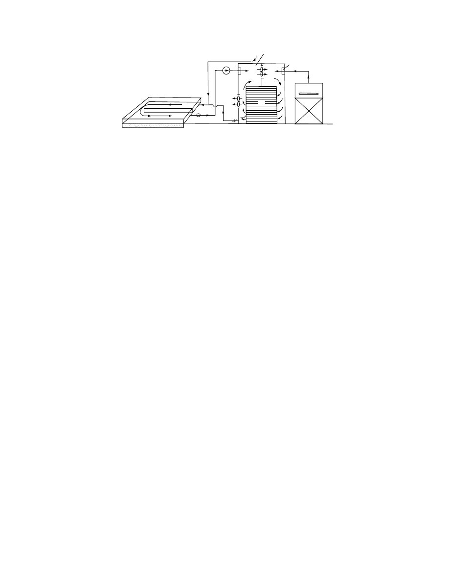
chamber through the da mpered duct 8. Fresh air,
slightl y preheat ed by the black -painted roo f surfa ce,
is led into the colle ctor through duc t 9. The wood
residu al burner 12 pro duces hot air for the drying
space that is dist ributed by the manif old 10. A hu-
midifier 11 is co upled to the bur ner for us e when the
humidi ty is be low the mini mum level.
13.7.4 .4.2 Direct ion and Cont rol of the Dryer
The operatio n of the dryer is directed and co ntrolled as
follows . Sola r blow ers 2 start when the tempe ratur e in
the drying space T
D
is lower than the colle ctor outlet
tempe rature T
c
, dampers 8 are open. Blo wers are acti -
vated by an on– off temperatur e con trol device. As a
precond ition of the operatio n of blo wers the relat ive
humidi ty U
1
should be low er than the set point value
U
1s
. Set poin t selection is manual . If U
1
< U
1s
the
interna l fans 4 are on. The ope ration of the exh aust
blowers 6 is con trolled by the signal of the relat ive
humidi ty sen sor U
2
sit uated behind the inter nal fans.
The set point U
2s
is high initial ly and should be reduced
in the progres s of drying. Exha ust blo wers are acti -
vated if U
2
> U
2s
. In the drying space the relat ive
humidi ty should also be ab ove a minimum level U
3s
.
When U
3
< U
3s
humidi fier 11 will be acti vated by the
control signal of the U
3
sensor. By applyi ng water
spray into the furnace chamber, humidi ficati on of the
air led to manifo ld 10 wi ll be effected. Opera tion of
the burner is direct ed by U
3
or man ually. The solar
blowers 2, the internal fans, the exhau st vents, the
humidi fier 11, and the dampers 8 can also be control led
manual ly by using bypass switche s. Wh en solar
blowers 2 are off, the internal fans 4 an d the exh aust
blowers 6 can be in ope ration if the stat e of the a ir in the
dryer satisfies the req uirements.
Dryi ng tim e can be influenced by the ope ration
time of the burner. For the sake of elect ric energy
saving the number of inter nal fans in operation can be
reduced, ge nerally, in the final pe riod of drying. In
this period the hum idifier 11 can be used for relief of
drying stre sses. The con trol of the drying pr ocess can
be perfor med accordi ng to a schedule by ap plying a
timer that ope ns or closes the co ntrol relay at a de -
termined time point. It c an be by passed manual ly.
When the dryer is out of operatio n, dampers 8 are
closed and the drying space can be isola ted from the
collectors (e.g., in the night).
13.7.4 .5 Direct ion and Control of Solar Dryers
with Water S torage
Solar dryers ap plying a water tank for he at storage
have an indirect he at transfer syst em: the working
medium of the co llector is liquid (e.g., wat er) and
the drying air shou ld be preheat ed in a liqui d–air
heat exchan ger. Two different constru ctions are dis-
cussed below.
13.7.4 .5.1 Cons truction an d Control of a Drye r
with Water Storage
The scheme of a simp le system is present ed in
. In this syst em three flow loop s are applie d.
The first is that of the collector- tank loop in whi ch the
flow of the liqui d working medium is maintained by
pump P1. The second loop is that of the tank-he at
exchanger with pump P2. The thir d one is the open
loop of the air that is trans ported by the fan through
the he at exchanger toward the drying space. Drying
air is preheated by the heat exchanger using water
from the heat storage tank.
Temperature required for drying T
D
is controlled
by control device CV using temperature sensor T
D
and valve V. Fan is in operation when T
D
is higher
than the lowest temperature limit as set point value
T
DS
. The fan is turned on by thermoswitch SD. The
minimal temperature level of the water needed for
ensuring T
D
is T
S
, which is the set point for the
temperature sensor in the tank T
T
. Operation of pump
P2 is induced by the thermal switch SP2. Pump P1
and the collector are in operation if the liquid outlet
temperature T
L
T
T
. The operation of the pump P1
is induced by the control device CP1. The controlling
signal is the temperature difference T
L
–T
T
.
1
6
8
2
9
3
10
4
T
c
T
D
U
3
U
2
U
1
5
12
11
x
o
x
x
7
FIGURE 13.52 Simplified scheme of an automatically controlled lumber kiln dryer.
ß
2006 by Taylor & Francis Group, LLC.
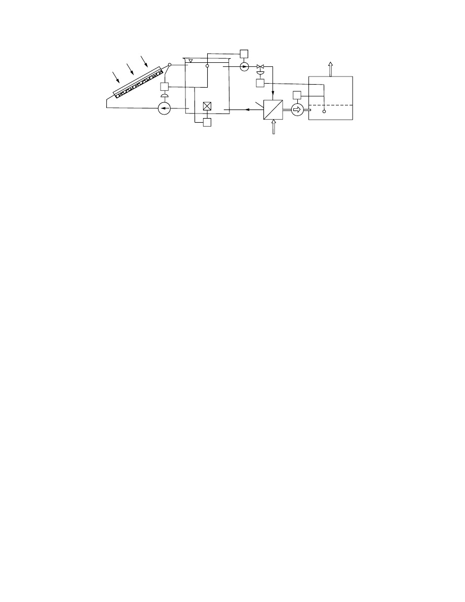
W hen T
T
is low er than the set point value, the
auxiliary energy sou rce in the tank (A.H.) wi ll turn
on. It is ope rated by on–o ff co ntrol device S.A. H.
Each of the control ope ration s can also be realized
manual ly using bypass switche s.
13.7.4 .5.2 Cons tructio n, Oper ation, an d Control
of a Com plex Solar Dr ying and Hot
Wate r Su pply Syst em
The applic ation of a hea t storage tank permi ts the
year-ro und utilization of solar energy colle cted. In the
idle periods of drying the heat stora ge can be charged
by the colle ctor and a hot water sup ply can be e n-
sured for other heat co nsumer s. The simp lified block
scheme of a complex solar dr ying and hot water
supply syst em is present ed in
. The sys-
tem can ope rate in five diff erent mod es of operati on.
1. Solar-on ly ope ration. Valves 2 and 3 are closed,
1 and 4 are open; the collector serves for the
heat exch anger of the dryer.
2. Simultaneou s ope ration for chargi ng the he at
storage and drying. Valve 3 is closed, valve 4 is
open, and 1 and 2 are in a partiall y ope ned
position.
3. Drying operati on by using store d energy. Val ves
1 and 4 are closed, 2 and 3 are open ; he at
exchanger operate s by using store d energy.
4. Charging the heat stora ge by the colle ctor.
Valves 1 and 3 are closed, 2 and 4 a re ope n.
Heat exchang er is out of operati on.
5. Techno logical hot wat er supp ly. Hot water
flow is induced by pump 2. This operation can
be realized simu ltaneou sly with other modes of
operation .
Tas ks of the direct ion and control syste m are the
selection of the mode of operati on, the con trol of
the inp ut tempe ratur es of the heat exc hanger, an d the
control of ch arging of the heat stora ge tank. A sch eme
of the control system is present ed in
. Four
control units are applie d (CU1–C U4).
CU 1 and CU 4 are value- keep ing co ntrollers for
the co ntrol of the outlet temperatur es of the colle ctor
and of the HWS he at exchanger, respect ively. Cont rol
signals are prod uced by the tempe rature sensors T
OC
and T
W
. Cont rol is realized by changing the mass flow
rates with one -way motor valves V
C
and V
W
, respect -
ively.
CU 3 serves for control ling the chargi ng of the
stratifie d heat stora ge tank T by the c ollector. As a
control signal the tempe ratur e difference ( T
L
–T
S
) is
applie d betw een the prim ary liquid ( T
L
) and the
stored wate r in the uppe r layer ( T
S
). Valve system
V
S
serves to direct the flow in the layer of ap propria te
tempe rature into the tank.
CU 2 pro cess control ler serves for au tomatic co n-
trolling of the inlet a ir tempe ratur e of the dryer T
OD
.
The aim is to direct the rate of drying and realize
intermit tent drying operati on in the falling rate period
of drying. As co ntrolling signals, the surfa ce tempe ra-
ture of the material under drying T
M
, the tempe rature
of the outlet T
out
, and of the ambie nt air T
a
, the
relative humidi ty of the outlet air U
out
, an d the am-
bient air U
a
are used. Cont rol is realized by adjust ing
the mass flow rate of the liquid steppin g into the he at
exchanger of the dryer by applyi ng the motor ic valve
V
D
. The other valves indica ted in the block scheme
serve for realizing the diff erent mode s of operatio n.
Cont rol of drying and selec tion of the ap propria te
mode of ope ration is directed by a micro process or.
The sim plified block scheme of the micr oprocessor is
present ed in
. As control signals the fol-
lowing parameters are used: temperature and relative
humidity of the ambient air T
a
and U
a
, respectively,
and that of the air step in and out of the dryer (T
OD
,
T
out
, U
out
), the actual inlet and outlet temperatures of
the liquid working medium of the collector, tempera-
ture distribution of the water in the storage tank,
temperature of the hot water produced for con-
sumers. The direction of the intermittent drying
Collector
CP1
P1
Tank
T
T
T
L
T
D
Air in
Fan
Air
out
Dryer
SD
P2
SP2
V
C.V
Heat
exchanger
A.H
S.A.H
FIGURE 13.53 Control scheme of a solar dryer with water storage.
ß
2006 by Taylor & Francis Group, LLC.
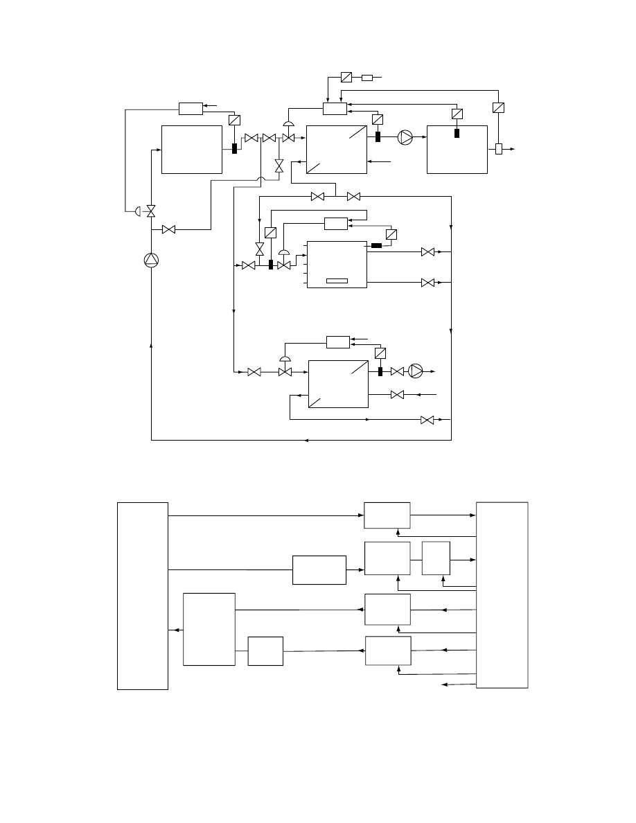
Heat
exchanger
of dryer
"d"
CU2
Preheated
air in
Drying
space
Air
out
Storage
tank
"T"
A.H.
CU4
Heat
exchanger
of "HWS"
HWS
CU3
Collector
"C"
CU1
Fan
Air
in
T
a,Ua
(ambient)
T
OD
V
D
V
C
P
C
T
OC
T
L
T
S
T
W
V
W
P
HWS
T
M
T
OUT
U
OUT
V
S
FIGURE 13.54 Scheme of the control system.
From switches
Analogous signals
Analogous signals
Measuring
transmitter
Digital switching signals
Intervening
units
Complex
solar
drying
system
Holding
units
Interface
Interface
Measuring
point
changing
D/A
Unit
A/D
Unit
Cont.
Cont.
Cont.
Cont.
Cont.
Digital signals
Micro-
computer
FIGURE 13.55 Block scheme of the microprocessor.
ß
2006 by Taylor & Francis Group, LLC.

process is realized by computing parameters serving
for the indication of the beginning and the time inter-
val of the break. A microprocessor forms commands
for the execution of the direction and control actions,
indicates the main information about the actual
state of the system, and calls attention to manual
interventions when needed.
13.8 PROSPECTS FOR SOLAR DRYING
Further research and development of various com-
ponents of solar drying systems continues to proceed
internationally. Major current applications are con-
fined to drying of agricultural and forest products.
Table 13.4 summarizes selected references on solar
drying of various materials.
Some significantly good payback times (1–7 years)
have been achieved [14,17,133], mainly with simple
and cheap dryers. The chances for the extensive use
of high-performance systems may be improved by
integrated construction and multipurpose operation.
Using modern process control techniques, the effi-
ciency of solar dryers can be increased. Due attention
must be paid to system maintenance and training of
the operating personnel.
In the design of solar dryers modern methods of
modeling and simulation can play an important role
in both the design and optimum operation. The re-
newable nature of solar energy is a definite asset in
most parts of the world.
NOMENCLATURE
a
specific transfer surface by volume basis, m
1
a
acceleration, m/s
2
A
area, m
2
b
biologic heat source, J/kg
1
c
specific heat capacity, J/(kg/K)
C
heat capacity, J/K
CU
control unit
&
heat capacity flow rate, W/K
d
h
hydraulic diameter, m
e
effectiveness
e
error
E
irradiance, W/m
2
f
efficiency function
f
Fanning coefficient
g
acceleration of gravity, m/s
2
h
heat transfer coefficient, W/(m
2
K)
H
heat exchanger effectiveness
I
global irradiance, W/m
2
k
heat conductivity, W/(m K)
K
heat conduction, W/K
K
gain of controller
L
length, m
M
mass, kg
_
m
m
mass flow rate, kg/s
N
mass flow rate of evaporation, kg/s
n
revolution, s
1
p
pressure, Pa
q
radiant flux density, W/m
2
TABLE 13.4
Solar Drying of Different Materials
Material
Refs
Agricultural products
155, 166
Banana
18
Coffee
3
Crop
3, 129, 138, 153, 155, 156, 158, 159, 161, 163, 164, 168, 173, 205
Fruits
3, 6, 11, 41
Garlic
12
Grain crops
3, 13–15, 19, 31, 128, 135, 148, 155, 167
Hay, herbage, grass
3, 13, 16, 132, 133, 135, 136, 141, 142, 171
Jute
3
Peanuts
3, 17, 19
Raisins
19, 143, 170
Rice
146, 219
Sorghum
140
Soybeans
19
Timber
3, 8–10, 19, 20, 29, 124, 133, 134
Tobacco
19, 137, 144, 145, 169
Tomato
139
Vegetables
3, 193, 194, 198
Lumber
162, 171, 172
ß
2006 by Taylor & Francis Group, LLC.

Q
radiant energy, J
r
heat of evaporation, J/kg
P
pump
R
resistance in a network
R
gas constant, J/(kg K)
S
switch
w
velocity, m/s
W
integral moisture content, kg/kg
W
water
z
height, m
t
transmittance
T
temperature, K
U
overall heat transfer coefficient, W/(m
2
K)
U
relative humidity of the air, %
V
value
x
absolute water content of the air by dry basis,
kg/kg
X
moisture content of the material, dry basis,
kg/kg
G
REEK
S
YMBOLS
a
absorbance
b
moisture transfer coefficient, m/s
«
emittance
f
heat flux, W
h
efficiency
h
dynamic viscosity, kg/(s m)
z
shape flow resistance coefficient
j
porosity
r
reflectance
r
mass density, kg/m
3
s
Stephan–Boltzmann constant
s
evaporation coefficient, kg/(m
2
s)
l
latent heat, J/kg
l
wavelength, m
n
frequency, s
1
t
time, s
S
UBSCRIPTS
A
auxiliary energy source
a, A
air
a
ambient
av
average
b
beam (direct)
b
bottom
b
break
c
collector
c
control
cr
critical
d, DIR direct
db
dry bulb
D
drying
e
equilibrium
f, F
fluid
h
heat
H–T
horizontal–total
i
incident
i,j
nodal points in a network
in
inlet
k
component
l
lag
l, L
loss
L
liquid
lt
long term
m
number of nodes in a network
m, M
material
n
number of the discrete parts
n
normal
o
outside atmosphere
O
set point
out
outlet
p
at constant pressure
r
reflected
R
reset
s
space
s
sky
S
set point
t, TOT
total
T
temperature
th
threshold
u
useful
v
vapor
w
water
wb
wet bulb
pw
for humid air
(k)
time period
’
inlet
’’
outlet
REFERENCES
1. P. Barbet, Panorama de l’E
´ nergie, 20:33 (1980).
2. Special issue, Sunworld, 4:179 (1980).
3. H.P. Garg, in Proceedings of the Third International
Drying Symposium (J.C. Ashworth, Ed.), Drying Re-
search Limited, Wolverhampton, England, 1982,
p. 353.
4. P. Wibulswas and C. Niyomkarn, Reg. Workshop on
Solar Drying, CNED-UNESCO, Manila, 1980, p. 1.
5. M.K. Selcuk, O
¨ . Ersay, and M. Akyurt, Solar Energy,
16:81 (1974).
6. J.R. Puiggali and M.A. Lara, in Proceedings of
the Third International Drying Symposium (J.C.
Ashworth, Ed.), Drying Research Limited, Wolver-
hampton, England, 1982, p. 390.
7. M.N. O
¨ zisik, B.K. Huang, and M. Toksoy, Solar
Energy, 24:397 (1980).
8. Re´sume´ de l’e´tude en cours on CTB sur l’utilization de
l’e´nergie solaire, Centre Technique du Bois, Paris, 1978.
ß
2006 by Taylor & Francis Group, LLC.

9. K.C. Yang, Forest Product J., 30:37 (1980).
10. A. Schneider, F. Engelhardt, and L. Wagner, Holz als
Roh-und Werkstoff , 37:427 (1979).
11. C. Rosello, A. Berna, and M. Mulet, Drying Technol-
ogy Int. J., 8(2):305 (1990).
12. F. Pinaga, J.V. Carbonell, and J.L. Pena, in Seventh
International Congress of Chemical Engineering Pra-
ha:C5.8 (1981).
13. W. Wieneke, Agricultural Mechanization in Asia ,
Autumn:11 (1980).
14. G.J. Schoenau and R.W. Besant, in Proceedings of the
Sharing the Sun, Solar Technology in the Seventies
(K.W. Bo¨ er, Ed.), Winnipeg, Canada, 7:33 (1976).
15. G. Roa and I.C. Macedo, Solar Energy , 18:445 (1976).
16. W. Dernedde and H. Peters, Landtechnik : 29 (1978).
17. D.H. Vaughan and A.J. Lambert, Trans. ASAE: 218
(1980).
18. R.G. Bowrey, K.A. Buckle, I. Hamey, and P. Pave-
nayotin, Food Technol. Australia , 32:290 (1980).
19. W.W. Auer, in Drying ’80 (A.S. Mujumdar, Ed.),
Hemisphere, New York, 1980, p. 292.
20. W.R. Read, A. Choda, and P.I. Cooper, Solar Energy ,
15:309 (1974).
21. P.W. Niles, E.J. Carnegie, J.G. Pohl, and J.M. Cherne,
Solar Energy , 20:19 (1978).
22. T.L. Freeman, J.W. Mitchell, and T.E. Audit, Solar
Energy , 22:125 (1979).
23. J.A. Duffie and N.R. Sheridan, Mech. and Chem.
Engr. Trans. Inst. Engrs ., Australia, MCI:79 (1965).
24. L. Imre, L.I. Kiss, and K. Molna´ r, in Proceedings of
the Third International Drying Symposium (J.C. Ash-
worth, Ed.), Drying Research Limited, Wolverhamp-
ton, England, 1982, p. 370.
25. L. Imre, I. Farkas, L.I. Kiss, and K. Molna´ r, in Third
International Conference on Numerical Methods in
Thermal Problems, Seattle, 1983.
26. L. Imre, in Handbook of Drying (in Hungarian), Mu¨ s-
zaki Konyvkiado, Budapest, 1974.
27. D.J. Close and L.L. Pryer, Solar Energy , 18:287
(1976).
28. D.J. Close and R.V. Dunkle, Solar Energy , 19:233
(1977).
29. N.A. Duffie and D.J. Close, Solar Energy , 20:505
(1978).
30. K.W. Bo¨ er, Solar Energy, 20:225 (1978).
31. O.Y. Kwon and P.J. Catania, in Drying ‘80 (A.S.
Mujumdar, Ed.), Hemisphere, New York, 1980, p. 445.
32. J.M. Gordon and A. Rabl, Solar Energy, 28:519
(1982).
33. J.S. Vaishya, S. Subrahmaniyam, and V.G. Bhide,
Solar Energy , 26:367 (1981).
34. M. Kovarik, Solar Energy, 21:477 (1978).
35. N.E. Vijeysundera, L.L. Ah, and L.E. Tijoe, Solar
Energy, 28:363 (1982).
36. J.P. Chiou, M.M. EI-Wakil, and J. A. Duffie, Solar
Energy, 9:73 (1965).
37. L. Imre and L.I. Kiss, in Numerical Methods in Heat
Transfer, Vol. 2 (R.W. Lewis, K. Morgan, and B.A.
Schrefler, Eds.), Wiley, Chichester, England, 1983,
38. D.J. Morrison and S.I. Abdel-Khalik, Solar Energy,
20:57 (1978).
39. M. Telkes and R.P. Mozzer, in Proceedings of the
Annual Meeting of the American Section of the Inter-
national Solar Energy Society, August 28–31, 1978,
Denver.
40. J.H. Schlag, D.C. Ray, A.P. Sheppard, and J.M.
Wood, Solar Energy, 20:89 (1978).
41. H.R. Bolin, A.E. Stafford, and C.C. Huxsoll, Solar
Energy, 20:289 (1978).
42. D.J. Close and M.B. Yusoff, Solar Energy, 20:459
(1978).
43. P.J. Lunde, Solar Thermal Engineering, Wiley, New
York, 1980.
44. S.H. Butt, J.W. Popplewell, W.S. Lymann, P. Ander-
son, P. Kruger, and S.C. Byone, Solar Age, 2:5 (1977).
45. W.A. Beckman, Solar Engineering, 21:531 (1978).
46. H.C. Hottel and B.B. Woertz, Trans. ASME, 64:91
(1942).
47. H.C. Hottel and A. Willier, Transactions of the Con-
ference on Use of Solar Energy, University of Arizona,
Vol. 2, 1955, pp. 74–104.
48. R.W. Bliss, Solar Energy, 3:55 (1959).
49. E. Marschall and G. Adams, Solar Energy, 20:413
(1978).
50. A. Whillier, in Low Temperature Engineering Applica-
tions of Solar Energy (R.C. Jordan, Ed.), ASHRAE,
New York, 1967.
51. J.P. Chiou, Solar Energy, 29:487 (1982).
52. H.S. Robertson and R.P. Patera, Solar Energy, 29:331
(1982).
53. ASHRAE STANDARD, ASHRAE Inc., New York,
1977.
54. J.E. Hill, J.P. Jenkins, and D.E. Jones, NBS Building
Science Series, 117, USDC, January 1979.
55. C.D. Adler, J.W. Byrd, and B.L. Coulter, Solar
Energy, 26:553 (1981).
56. J.A. Duffie and W.A. Beckman, Solar Engineering of
Thermal Processes, Wiley, New York, 1980.
57. K.S. Ong, Solar Energy, 16:137 (1974).
58. A.A. Sfeir, Solar Energy, 25:149 (1980).
59. A.J. De Rou, Solar Energy, 24:117 (1980).
60. W.F. Phillips, Solar Energy, 29:77 (1982).
61. L. Imre, Heat Transfer of Composite Devices (in Hun-
garian), Budapest, Hungary, 1983.
62. G.O.G. Lo¨f, J.A. Duffie, and C.O. Smith: Solar En-
ergy Laboratory, University of Wisconsin, Report No.
21, 1966.
63. J.I. Yellott, in NAS Conference Proceeding, 1976.
64. Climatic Atlas of the United States, U.S. Government
Printing Office, 1968.
65. C.R. Attwater et al., Canadian Solar Radiation Base,
ASHRAE Arm. Meeting, Detroit, 1979.
66. Catalogue of Solar Radiation Data, Australian Govern-
ment Publishing Service, Canberra, 1979.
67. Beuzeman and Cook, N.Z.J. Sci., 12:698 (1969).
68. N.K.O. Choudhury, Solar Energy, 4:44 (1963).
69. Anderson et al., Extract from Meteorological Data,
Thermal Insulation Laboratory, Technical University,
Denmark, 1974.
ß
2006 by Taylor & Francis Group, LLC.

70. K.R. Rao and T.N. Sechadri, Ind. J. Meteor. Geo-
phys., 12:267 (1961).
71. A.A. Sefir, Solar Energy, 26:497 (1981).
72. J.W. Spencer, Solar Energy , 29:19 (1982).
73. M. Iqbal, Solar Energy , 22:81 (1979).
74. G. Stanhill, Solar Energy, 10:96 (1966).
75. P. Berdahl and R. Fromberg, Solar Energy, 29:299
(1982).
76. A.I. Kudish, D. Wolf, and Y. Machlav, Solar Energy ,
30:33 (1983).
77. E. Scerri, Solar Energy , 28:353 (1982).
78. W. Palz (Ed.), Atlas u¨ ber die Sonnenstrahlung in Eur-
opa, Komm. Eur. Gemeinsch ., Gro¨ sschen VI, Dort-
mund, 1979.
79. G. Haurwitz, J. Meteorol., 5:110 (1948).
80. M.A. Atwater, P.J. Lunde, and G.D. Robinson, ISES
Silver Jubilee Congress , Atlanta, 1979.
81. B. Choudhury, Solar Energy , 29:479 (1982).
82. C. Castagnoli et al., Solar Energy , 28:289 (1982).
83. D.G. Erbs, S.A. Klein, and J.A. Duffie, Solar Energy ,
28:393 (1982).
84. R. Walraven, Solar Energy , 20:393 (1978).
85. W.D. Dickinson, Solar Energy , 21:249 (1978).
86. P. Doratio and M. Jamshidi, Solar Energy , 29:351
(1982).
87. K.J.A. Revfeim, Solar Energy , 28:509 (1982).
88. K. Scharp, Solar Energy, 2:531 (1982).
89. I.M. Gordon and Y. Zarmi, Solar Energy , 28:483
(1982).
90. W.C. Swinbank, Q.J. Royal Meteorol. Soc ., 89:1963.
91. R.W. Bliss, Solar Energy , 5 :103 (1961).
92. J. Yellot and Kokoropsulos, in Proceedings of the UN
Conference on New Sources of Energy , Paper No. 5/34,
Rome, 1961.
93. K.G. Picha and J. Villanueva, Solar Energy , 6:151
(1962).
94. M. Centeno, Solar Energy , 28 :489 (1982).
95. E.M. Sparrow, J.S. Nelson, and W.Q. Tao, Solar
Energy , 29:33 (1982).
96. L. Imre, in Numerical Methods in Heat Transfer, Vol.
1 (R.W. Lewis, K. Morgan, and O.C. Zienkiewicz,
Eds.), Wiley, Chichester, England, 1981, p. 51.
97. D.C. Zienkiewicz, Finite Element Analysis in Engineer-
ing Science , McGraw-Hill, New York, 1978.
98. B.J. Huang and J.H. Lu, Solar Energy, 28:413 (1982).
99. D.L. Evans, T.T. Rule, and B. Wood, Solar Energy,
28:13 (1982).
100. W.R. Petrie and M. McClintock, Solar Energy, 28:13
(1982).
101. S.B. Marks, Solar Energy, 30:45 (1983).
102. M. Telkes, in Critical Materials in Energy Production,
Academic Press, New York, 1978,
103. G. Comini, S. Del Guidice, R.W. Lewis, and O.C.
Zienkiewicz, Int. J. Num. Meth. Eng., 8:613 (1974).
104. I. Benko¨ and L.I. Kiss, in Energy Conservation in
Heating, Cooling and Ventilating Buildings, Vol. 1
(C.J. Hoogendorn and W.H. Afgan, Eds.), Hemi-
sphere, Washington, D.C., 1978, p. 251.
105. I. Tanishita, in Melbourne International Solar Energy
Society Conference, 1970.
106. Y. Jaluria and S.K. Gupta, Solar Energy, 28:137
(1982).
107. W.F. Phillips and R.N. Dave, Solar Energy, 29:111
(1982).
108. M. Sokolov and M. Vaxmann, Solar Energy, 30:237
(1983).
109. C.S. Herrick, Solar Energy, 28:99 (1982).
110. D.Y.S. Lou, Solar Energy, 30:115 (1983).
111. C. Vaccarino and T. Fioravanti, Solar Energy, 30:123
(1983).
112. A. Abhat and T.Q. Huy, Solar Energy, 30:93 (1983).
113. R.F. Childs, D.L. Mulholland, M. Zeya, and A.K.
Goyal, Solar Energy, 30:155 (1983).
114. R. Gopal, B.R. Hollebone, C.H. Langford, and R.A.
Shigeishi, Solar Energy, 28:421 (1982).
115. D.M. Brooks and R.N. Dave, Solar Energy, 29:129
(1982).
116. S.C. Klein et al., Solar Energy, 17:29 (1975).
117. A.H. Eltimsahy and C.H. Copass, Math. Computers in
Simul., XX:114 (1978).
118. S.A. Klein and W.A. Beckmann, ASHRAE Trans.,
82:623 (1976).
119. W.A. Beckmann, S.A. Klein, and J.A. Duffie, Solar
Heating Design by f-Chart Method, John Wiley &
Sons, New York, 1977.
120. M.E. McBabe, ASHRAE Trans., 86:420 (1980).
121. S.A. Klein and W.A. Beckmann, Solar Energy, 22:269
(1979).
122. H.F.W. DeVries and J.C. Franken, Solar Energy,
25:279 (1980).
123. M.K. Selcuk et al., Int. Solar Energy, 16:81 (1975).
124. D.J. Close, International Solar Energy Congress, Los
Angeles, 1975.
125. L. Imre, I.L. Kiss, T. Ko¨rnyey, and K. Molna´r, in
Drying ’80 (A.S. Mujumdar, Ed.), Hemisphere, New
York, 1980, p. 446.
126. L. Imre and I. Szabo´, in Proceedings of the First Inter-
national Drying Symposium (A.S. Mujumdar, Ed.),
Science Press, Princeton, 1978, p. 76.
127. P. Doratio, Solar Energy, 30:147 (1983).
128. S. Pabis, in Proceedings of the Agricultural Engineering
Symposium, Silsoe, England, 1967.
129. T.L. Thomson, R.M. Peart, and G.H. Foster, Trans.
Am. Soc. Agric. Engrs., 11:582 (1968).
130. G.W. Ingram, J. Agric. Eng. Res., 21:263 (1976).
131. L. Imre and K. Molna´r, in Proceedings of the Third
International Drying Symposium, Vol. 2 (J.C. Ash-
worth, Ed.), Birmingham, England, 1982, p. 73.
132. L. Imre, K. Molna´r, and S. Szentgyo¨rgyi, in Drying
‘83 (A.S. Mujumdar, Ed.), Hemisphere, Washington,
D.C., 1984.
133. JAKRAP SOLARKILN, Technical Inf. Sheet, Fuels
Ltd., Silverburn, Penicuik, U.K.
134. H.N. Rosen and P.Y.S. Chen, AIChE, 76(200):82
(1980).
135. A. Kangro, Sveriges Landbruksuniversitet, Specielmed-
delande, 111, Lund, 1981.
136. W.E. Ferguson and P.A. Bailey, in Proceedings of the
International Solar Energy Society Congress, Brighton,
England, 1981, Pergamon Press, Oxford, 1982, p. 1006.
ß
2006 by Taylor & Francis Group, LLC.

137. L. Andreotti et al., in Solar Energy International Pro-
gress, Vol. 3 (T.N. Veziroglu, Ed.), Pergamon Press,
New York, 1980, p. 1645.
138. P.W. Niles et al., Solar Energy, 20:19 (1978).
139. A.M.A. El-Bassononi and A.M. Tayeb, in Proceedings
of the Third International Drying Symposium, Birming-
ham, England, Vol. 1 (J.C. Ashworth, Ed.), Drying
Research Limited., Wolverhampton, England, 1982,
p. 385.
140. A.P. Soponronnarit, in Proceedings of the Third Inter-
national Drying Symposium , Birmingham, England,
Vol. 1 (J.C. Ashworth, Ed.), Drying Research Limited,
Wolverhampton, England, 1982, p. 375.
141. J.P. Ratschow and H.G. Claus, Landtechnik , 1, (1978).
142. U. Facchini and G. Frosi, Sunworld , 3:160 (1979).
143. B.W. Wilson, Australian J. Agric. Res ., 13:662 (1962).
144. B. Sadikov, A. Vardjasvili, and T. Sadikov, Geliotech-
nika, 5:77 (1976).
145. C. Artikov and T.M. Maksudov, Geliotechnika , 1:72
(1978).
146. T. Mackawa, K. Toyoda, and K. Matsumoto, in Dry-
ing ’82 (A.S. Mujumdar, Ed.), Hemisphere, Washing-
ton, D.C., 1982.
147. A.K. Mahapatra and L. Imre, Int. J. Ambient Energy ,
4: 205 (1990).
148. C.G. Odunukwe, in Proceedings of the Biennial Con-
gress of ISES , Vol. 3, Pergamon Press, Hamburg,
FRG, 1987, p. 2515.
149. C. Wereko-Brobby, in Proceedings of the Workshop on
Solar Drying in Africa , Dakar, Senegal, 1986, p. 147.
150. N.K. Bansal et al., Sun World, 8(1):9 (1984).
151. B. Norton and O.V. Ekechukwu, Solar Thermal and
Photovoltaic Conversion , Workshop, Dhaka, Bangla-
desh, 1987.
152. A.K. Mahapatra and L. Imre, Int. J. Ambient Energy ,
10(3):163 (1989).
153. D.K. McDaniels, The Sun: Our Future Energy Source ,
2nd ed., John Wiley & Sons, New York, 1984, p. 138.
154. J.C. McVeigh, Sun Power , Pergamon Press, Oxford,
1977, p. 17.
155. J. Nagirju et al., in Proceedings of the Biennial Con-
gress of ISES , Vol. 3, Pergamon Press, Hamburg,
FRG, 1987, p. 2538.
156. N. Sitthiphong and P. Terdtoon, in Proceedings of the
Biennial Congress of ISES, Vol. 3, Pergamon Press,
Hamburg, FRG, 1987, p. 2528.
157. F.B. Sebbowa, in Proceedings of the Workshop on
Solar Drying in Africa , Dakar, Senegal, 1986, p. 60.
158. W.O.N. Harvey et al., in Proceedings of the Biennial
Congress of ISES, Vol. 2, Pergamon Press, Montreal,
Canada, 1985, p. 1082.
159. C.J. Minka, in Proceedings of the Workshop on Solar
Drying in Africa, Dakar, Senegal, 1986, p. 11.
160. M. Dicko, in Proceedings of the Workshop on Solar
Drying in Africa, Dakar, Senegal, 1986, p. 75.
161. Y.K.L. Yu Wai Man, in Proceedings of the Workshop
on Solar Drying in Africa , Dakar, Senegal, 1986, p. 92.
162. R. Martinez et al., Solar Wind Technol ., 4:223 (1984).
163. E.A. Arinze, in Proceedings of the Workshop on Solar
Drying in Africa, Dakar, Senegal, 1986, p. 128.
164. M.W. Bassey et al., in Proceedings of the Workshop
on Solar Drying in Africa, Dakar, Senegal, 1986,
p. 207.
165. K. Amonzon et al., in Proceedings of the Workshop on
Solar Drying in Africa , Dakar, Senegal, 1986, p. 252.
166. I. Segal and M. Reuss, in Proceedings of the Biennial
Congress of ISES , Vol. 3, Pergamon Press, Hamburg,
FRG, 1987, p. 2368.
167. V. Muthuveerappan et al., in Proceedings of the Bien-
nial Congress of ISES , Vol. 2, Pergamon Press, Mon-
treal, Canada, 1985, p. 1077.
168. V. Asiedu-Bondzie and A. Ayensu, in Proceedings of
the ANSTII Symposium on Renewable Energy for De-
velopment , Vol. 2, Kumasi, Ghana, 1986, p. 160.
169. S. Janjai, V. Guevezov, and M. Daguenet, Drying
Technol. Int. J., 4(4):605 (1986).
170. G.S. Rauzeous and G.D. Saravacos, Drying Technol.
Int. J., 4(4):633 (1986).
171. J. Muller et al., Solar Wind Technol ., 5:523 (1989).
172. M.A. Sattar, in Proceedings of the First World Renew-
able Energy Congress , Vol. 2, Reading, UK (A.A.M.
Sayigh, Ed.), Pergamon Press, Oxford, 1990, p. 59.
173. H.P. Garg, in Proceedings of the First World Renew-
able Energy Congress, Vol. 2, Reading, UK, (A.A.M.
Sayigh, Ed.), Pergamon Press, Oxford, 1990, p. 618.
174. Futal Huang et al., in Proceedings of the First World
Renewable Energy Congress, Vol. 2, Reading, UK
(A.A.M. Sayigh, Ed.), Pergamon Press, Oxford,
1990, p. 633.
175. L. Imre, in Proceedings of the X Congress on Energy ,
Opatija, Yugoslavija, 1988, p. 23.
176. L. Imre, in Proceedings of the ASRE 86 Symposium ,
Vol. 2, Cairo, Egypt, 1986, p. 1105.
177. L. Imre, Direction and control of solar dryers, in
Manual of Industrial Solar Dryers , UNESCO Report
(M. Daguenet, Ed.), 1988,
178. L. Imre, in Proceedings of the Fourth International
Drying Symposium , Vol. 1, Kyoto, Japan (R. Toei
and A.S. Mujumdar, Eds.), 1984, p. 43–50.
179. P. Harriott, Process Control, McGraw-Hill, New
York, 1964.
180. M. Gopal, Modern Control Systems Theory , John
Wiley & Sons, Chichester, 1984.
181. K. Ogata, Modern Control Engineering , Prentice-Hall,
Englewood Cliffs, NJ, 1970.
182. J.L. Tsernitz and W.T. Simpson, Drying Technol. Int.
J., 4(4):651 (1986).
183. L. Imre, I. Farkas, and L. Ge´ mes, in Drying ’86 (A.S.
Mujumdar, Ed.), Vol. 2, 1986, p. 678.
184. K. Lutz and W. Mu¨ hlbauer, Drying Technol. Int. J.,
4(4):583 (1986).
185. L. Imre et al., Drying Technol. Int. J., 8(2):343 (1990).
186. M. Hasnaoui, G. Le Palec, and M. Daguenet, Revue
Ge´ ne´ ral de Thermique , XXIII :(265):7 (1984).
187. M. Daguenet, Solar Dryers. Theory and Practice (in
French), UNESCO, Paris, 1985.
188. M. Daguenet, Methodology for calculation of solar-
assisted convective dryers, in Manual of Industrial
Solar Dryers (M. Daguenet, Ed.), UNESCO Report,
1988,
ß
2006 by Taylor & Francis Group, LLC.

189. B. Norton and P.A. Hobson, Thermal analysis of
thermosyphon solar energy crop dryers, in Manual of
Industrial Solar Dryers (M. Daguenet, Ed.), UNESCO
Report, 1988.
190. J.R. Puiggali and A. Tiguert, Drying Technol. Int. J.,
4(4):555 (1986).
191. A. Tiguert and J.R. Puiggali, A modelling approach to
the performance of a country solar dryer, in Manual of
Industrial Solar Dryers (M. Daguenet, Ed.), UNESCO
Report, 1988.
192. A. Steinfeld and I. Segal, Drying Technol. Int. J.,
4(4):535 (1986).
193. D. Stehli and F. Escher, Drying Technol. Int. J.,
8(2):241 (1990).
194. B.G. Patil and G.T. Ward, Solar Energy, 43(5):305
(1989).
195. D.A. Weitz, E.A. Lugue, and R.D. Piacentini, Drying
Technol. Int. J., 8(2):287 (1990).
196. L. Imre, Drying Technol. Int. J., 4(4):503 (1986).
197. L. Imre, in Proceedings of the ASRE 89 Symposium,
Vol. 2, Cairo, Egypt, 1989, p. 1029.
198. M. Tsamparlis, Drying Technol. Int. J., 8(2):261
(1990).
199. L. Imre, G. Hecker, and L. Fa´bri, in Proceedings of the
ISES Solar World Congress, Vol. 2. Part 2, Denver,
CO, Pergamon, Oxford, 1991, p. 2184.
199. L. Imre, G. Hecker, and L. Fa´bri, Solar assisted high
performance solar dryer, in Proceedings of ISES Solar
World Congress, Vol. 2, Part II, Denver, CO, 1991,
pp. 2184–2188.
200. W. Mu¨hlbauer, A. Esper, and J. Mu¨ller, Solar energy
in agriculture, in Proceedings of ISES Solar World
Congress, Vol. 8, Budapest, 1993, pp. 13–30.
201. L. Imre, General aspects for designing solar dryers, in
Proceedings of Expert Workshop on Drying and Con-
servation with Solar Energy, Budapest, 1993, pp. 7–13.
202. J.W. Twidell, J. Muniba, and T. Thornwa, The Strath-
clyde solar crop dryer: air heater, photovoltaic fan
and desiccants, in Proceedings of ISES Solar World
Congress, Vol. 8, Budapest, 1993, pp. 55–60.
203. G.D. Wisniewski, Methods of rational solar collectors
selection for crop drying, in Proceedings of ISES Solar
World Congress, Vol. 8, Budapest, 1993, pp. 97–102.
204. N.K. Bansal and O.P. George, in Drying ’80 (A.S.
Mujumdar, Ed.), Hemisphere, New York, 1993, p. 15.
205. W.W.S. Charters and K.R. James, Solar crop dryers,
in Proceedings of ISES Solar World Congress, Vol. 8,
Budapest, 1993, pp. 31–36.
206. A.K. Mahapatra, L. Imre, J. Barcza, A. Bitai, and I.
Farkas, Int. J. Ambient Energy, 15:195 (1994).
207. O. Hamminger, Erneubare Energie, 2:34 (1994).
208. C. Chondhury, P.M. Chanhan, and H.P. Garg, Solar
Energy, 55:29 (1995).
209. A.K. Mahapatra and L. Imre, Parameter sensitivity
analysis of a directly irradiated solar dryer with inte-
grated collector, in Proceedings of ISES Solar World
Congress, Harare, Maha 0044, 1995.
210. L. Imre, Solar dryers, in Industrial Drying of Foods
(C.G.J. Baker, Ed.), Blackie Academic and Profes-
sional, London, 1997.
211. S. Busano, The application of solar tunnel dryer in
Indonesia, in Proceedings of World Renewable Energy
Congress VI, Part IV, Brighton, 2000, pp. 2194–2197.
212. C. Cheapok and P. Pornnareay, Introducing solar
drying in a developing country: the case of Cambodia,
in Proceedings of World Renewable Energy Congress
VI, Part IV, Brighton, 2000, pp. 2198–2201.
213. S. Ben Mabrouk and A. Belghith, Development of the
solar crop dryers in Tunisia, in Proceedings of World
Renewable Energy Congress VI, Part IV, Brighton,
2000, pp. 2206–2211.
214. C.B. Joohi, B.D. Pradhan, and T.P. Pathak, Applica-
tion of solar drying systems in rural Nepal, in Pro-
ceedings of World Renewable Energy Congress VI, Part
IV, Brighton, 2000, pp. 2237–2240.
215. H.P. Garg and R. Kumer, Performance simulation
model of natural convection type solar tunnel dryer,
in Proceedings of World Renewable Energy Congress
VI, Part IV, Brighton, 2000, pp. 2269–2272.
216. A.A. Sehery, Y.M. Callali, and M.J. Wafa, Preserva-
tion of fruits and vegetables using solar energy, in
Proceedings of World Renewable Energy Congress VI,
Part IV, Brighton, 2000, pp. 2167–2169.
217. K. Sopian, M.Y. Othman, B. Yatim, and M.H. Rus-
lan, Experimental studies on a solar assisted drying
system for herbal tea, in Proceedings of World Renew-
able Energy Congress VI, Part IV, Brighton, 2000,
pp. 1139–1142.
218. B. Zimberg, J.F. Mathisson, and V. Sica, Solar drying
of herbs, numerical simulation and experimental re-
sults, in Proceedings of World Renewable Energy Con-
gress VI, Part IV, Brighton, 2000, pp. 1153–1156.
219. S.C. Bhattacharya, T. Ruangrungchaikul, and H.L.
Pham, Design and performance of a hybrid solar/bio-
mass energy powered dryer for fruits and vegetables,
in Proceedings of World Renewable Energy Congress
VI, Part IV, Brighton, 2000, pp. 1161–1164.
220. R.R. del Mundo, A hybrid solar-biomass drying sys-
tem for ceramic wares, in Proceedings of World Re-
newable Energy Congress VI, Part IV, Brighton, 2000,
pp. 1091–1093.
221. G. Alvarez, E. Sima, and L. Lira, Thermal perform-
ance of an indirect solar dryer, in Proceedings of World
Renewable Energy Congress VI, Part IV, Brighton,
2000, pp. 1165–1169.
222. O. Stc. Headley, Solar crop drying in the West Indies,
in Proceedings of World Renewable Energy Congress
VI, Part IV, Brighton, 2000, pp. 934–939.
223. M.Y. Othman, K. Sopian, B. Yatim, and W.R.W.
Dond, Solar drying technology for agricultural pro-
duce, in Proceedings of World Renewable Energy Con-
gress VI, Part IV, Brighton, 2000, pp. 922–927.
224. S. Toure, S. Kibangou, and N. Kombo, Numerical
model and experimental study of natural solar drying
of Cassava in Abidjan/Cote d’Ivoire/, in Proceedings
of World Renewable Energy Congress VI, Part IV,
Brighton, pp. 2155–2158.
225. A. Kamaruddin, Dissemination of GHE solar dryer in
Indonesia, in Proceedings of World Renewable Energy
Congress VI, Part IV, Brighton, pp. 2159–2162.
ß
2006 by Taylor & Francis Group, LLC.

226. F. Nydegger, Erneubare Energie, 2:29 (2000).
227. A. Mulat, A. Berna, C. Rossello, and J. Canellas,
Drying Technol., 11(6):1385 (1993).
228. I. Seres, L. Pont, and I. Farkas, The use of solar
energy in fruit drying, in IDS 2000, Noordwijkerhout,
Paper No. 167, 2000.
229. A.Y. Gibriel, A.F. El-Saghiri, N.M. Rasmy, Y.A.
Heikal, and H.K. Ibrahim, Dehydration of apricots
and grapes using solar dehydration, in IDS 2000,
Noordwijkerhout, Paper No. 392, 2000.
ß
2006 by Taylor & Francis Group, LLC.

Document Outline
- Table of Contents
- Chapter 013: Solar Drying
- 13.1 Introduction
- 13.2 Aspects and Limitations of Solar Drying
- 13.3 Construction Principles of Solar Dryers
- 13.4 Economics of Solar Dryers
- 13.5 Key Elements of Solar Dryers
- 13.6 Simulation of Solar Dryers
- 13.6.1 Purpose of Simulation
- 13.6.2 Methods of Simulation
- 13.6.3 Simulation Model of Solar Dryers
- 13.6.4 Strategy of Solution
- 13.6.5 Results of Simulation
- 13.7 Direction and Control of Solar Dryers
- 13.7.1 Aims of the Direction and Control
- 13.7.2 Direction and Control Actions
- 13.7.3 Principles of the Direction
- 13.7.3.1 Direction Strategy of Static Bed Solar Dryers
- 13.7.3.2 Direction of Operation of Static Bed Dryers
- 13.7.3.3 Direction of Solar Dryers with Heat Transfer by Convection and Direct Irradiation
- 13.7.3.4 Direction of the Operation of Tent, Greenhouse, and Cabinet-Type Solar Dryers
- 13.7.3.5 Direction of the Operation of Chimney-Type Solar Dryers
- 13.7.4 Basic Principles of Control
- 13.7.4.1 Application of Automatic Control
- 13.7.4.2 Control of Solar Dryer Operating with Recirculation
- 13.7.4.3 Direction and Control of Solar Dryers with Rock-Bed Heat Storage
- 13.7.4.4 Automatically Controlled Solar Dryer with Auxiliary Heater
- 13.7.4.5 Direction and Control of Solar Dryers with Water Storage
- 13.8 Prospects for Solar Drying
- Nomenclature
- References
Wyszukiwarka
Podobne podstrony:
GATE Solar Drying Technology for Food Preservation
Solar food drying By Marcella Shaffer
Solar
40 0610 013 05 01 7 General arrangement
[ebook renewable energy] Home Power Magazine 'Correct Solar Panel Tilt Angle to Sun'
013 ROZ M T G M w sprawie warunków technicznych, jakim pow
art 10 1007 s00482 013 1385 z
013 (3)
013 HISTORIA SZTUKI WCZESNOCHRZEŚCIJAŃSKIEJ I BIZANTYJSKIEJ, WYKŁAD,# 02 10
bądźże pozdrowiona, (Finale 2006c [B 271d 237 277e pozdrowiona 013 R 363g Es 3 4 MUS])
013
Drying kinetics and drying shrinkage of garlic subjected to vacuum microwave dehydration (Figiel)
DIY Combination Solar Water and Nieznany
03 0000 013 02 Leczenie przedwczesnego dojrzewania plciowego
metody 013
p13 013
p08 013
Improving Grape Quality Using Microwave Vacuum Drying Associated with Temperature Control (Clary)
013
więcej podobnych podstron