
GEISLINGER COUPLING
INSTRUCTION AND MAINTENANCE
MANUAL
Niigata Power System Co., Ltd.
M8090901A


- 1 -
Page
SECTION 1
: Structure...............................................................................................2
1.1
Working principle ..........................................................................................2
1.2
Structure........................................................................................................2
1.3
Name Plates...................................................................................................7
1.4
Specification of coupling..............................................................................10
SECTION 2
: Installation .........................................................................................15
2.1
Installation Tolerance .................................................................................15
2.1.1
Tolerance of distance between input and output shaft flanges..........15
2.1.2
Tolerance of center misalignment of input and output shaft.............15
2.1.3
Tolerance of angular misalignment of input and output shaft ..........15
2.2
Installation of Geislinger coupling .............................................................16
2.2.1
Installation procedure..........................................................................16
SECTION 3
:Operation .............................................................................................18
3.1
Lubrication Oil Filling Procedure ..............................................................18
SECTION 4
:Preventive Maintenance .....................................................................19
4.1
Periodical Preventive Maintenance............................................................19
4.2
Inspection Points and Replacement Criteria.............................................19
4.2.1
Inner Star .............................................................................................19
4.2.2
Flange and Lateral Plate .....................................................................19
4.2.3
Spring Block .........................................................................................20
4.2.4
Long Leaf ..............................................................................................20
4.2.5
Shim ......................................................................................................20
4.2.6
Oil Vent Mechanism at the center of Oil Stop Ring ...........................20
4.2.7
Bolt for Intermediate Piece..................................................................21
4.2.8
O-rings (for inner star and oil stop ring).............................................21
4.2.9
Other O-rings........................................................................................21
SECTION 5
:Disassembly.........................................................................................22
5.1
Disassembly.................................................................................................22
5.2
Disassembly lateral plate ...........................................................................23
SECTION 6
:Assembly..............................................................................................24
6.1
Assembly......................................................................................................24
6.2
Assembly of lateral plate ............................................................................25

- 2 -
SECTION 1
: Structure
1.1 Working
principle
In this coupling, since one end of each leaf spring is fixed with the outer
circumference part and the other is freely (loosely) held at the inner
circumference part, both outer and inner circumference parts can
relatively make much displacement by means of deflection of the leaf
spring.
The lubrication oil inside the coupling works to make the springs slide
smoothly when the leaf spring deflects.
It also absorbs energy and reduces vibration against torsion when it flows
through its damping clearance during spring deflection.
1.2 Structure
In this coupling, the inner member consists of an inner star and oil seal
ring. The outer member consists of a clamping ring, intermediate ring,
intermediate piece, spring block, etc. Leaf springs radiate between the
inner and outer parts and lubrication oil fills the inside spaces.
The inner and outer member are sealed by O-rings which prevent oil
leakage.
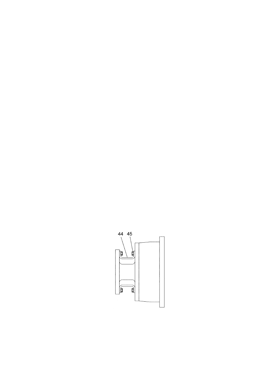
Supporting pieces, as shown in Figure 1-1, are attached to prevent O-ring
damage when the coupling is moved or transported.
44 Supporting pieces
45 Bolts
Figure 1-1
- 3 -
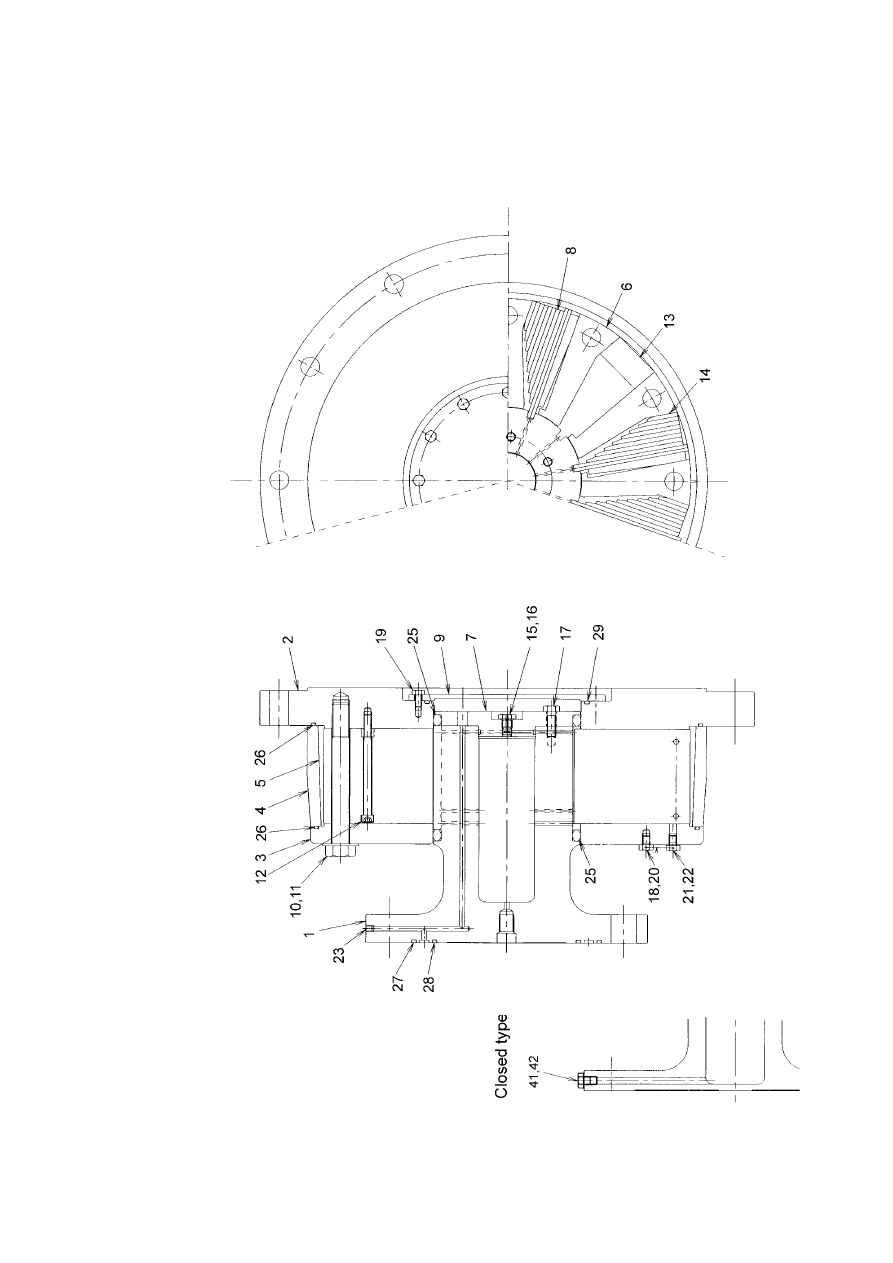
Figure. 1-2 Shows the Structure of the GEISLINGER COUPLING
(BC type)

- 4 -
Table 1-1 shows parts names of the coupling ( BC type )
Table 1-1 Parts of BC type
Ref. No.
Part Name
Ref. No.
Part Name
1 Inner
star
16 Packing
2
Flange (Driving Side)
17
Bolt
3
Lateral Plate (Cover)
18
Wire
4 Clamping
Ring
19 Bolt
5 Intermediate
Ring
20 Plug
6
Intermediate Piece
21
Air Vent Plug
7
Oil Stop Ring
22
Packing
8 Spring
Block
23 Screw
9 Cover
24
10
Bolt for Intermediate Piece
25
O-rings
11
Conical Spring Washer
26
O-rings
12 Hexagon
Socket
Screw
27 O-rings
13 Intermediate
block
28 O-rings
14 Shim
29 O-rings
15 Plug
30
Closed type
41 Plug
42 Packing
- 5 -
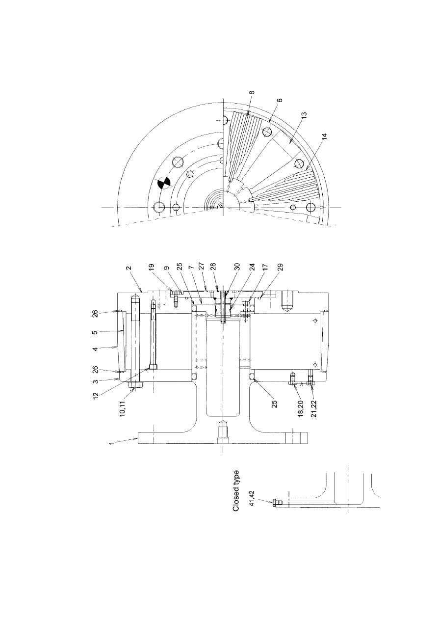
Figure. 1-3 Shows the Structure of the GEISLINGER COUPLING
(BE type)
- 6 -
Table 1-2 shows parts names of the coupling ( BE type )
Table 1-2 Parts of BE type
Ref. No.
Part Name
Ref. No.
Part Name
1 Inner
star
16
2
Flange (Driving Side)
17
Bolt
3
Lateral Plate (Cover)
18
Wire
4 Clamping
Ring
19 Bolt
5 Intermediate
Ring
20 Plug
6
Intermediate Piece
21
Air Vent Plug
7
Oil Stop Ring
22
Packing
8 Spring
Block
23
9 Cover
24 O-rings
10
Bolt for Intermediate Piece
25
O-rings
11
Conical Spring Washer
26
O-rings
12 Hexagon
Socket
Screw
27 O-rings
13 Intermediate
block
28 O-rings
14 Shim
29 O-rings
15
30 Oil
Pipe
Closed type
41 Plug
42 Packing
- 7 -
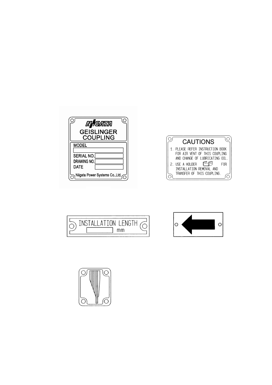
1.3 Name
Plates
All models of this Geislinger Coupling are equipped with name plates showing
Model, as shown in Figure 1, Precaution, as shown in Figure 2, and Installation
Length, as shown in Figure 3. These are mounted on the lateral plate.
In addition, non-reversible type couplings have two additional name plates on
the same side plate which show Rotating Direction, as shown in Figure 4, and
Spring Arrangement, as shown in Figure 5.
The followings are the descriptions of the respective nameplates.
Figure 1
Figure 2
Figure 3
Figure 4
Figure 5
- 8 -
Guide to Model Name Plate Figures
Model
(Example)
B E 56/15/140U-12 RO
RO :
means that filling/removing of
lubrication oil must be done from the
driving side plate.
In addition:
T :
indicates model which is equipped
with a thrust-ring for positioning on
the driving side plate.
R :
indicates model with bearings between
input side and output side.
S :
indicates model with an installed
dimension which is shorter than
standard
F :
indicates a coupling in which the
lubrication oil is sealed.
NO symbol :
means that filling/removing of
lubrication oil must be done
from inner star side.
:shows number of spring blocks.
:shows type of spring block.
:shows width of spring blocks
:shows maximum diameter of clamping
ring.
:shows flange shape of driving side plate.
:shows shape of inner star flange.
SERIAL NO. :
shows the number of serial products.
DRAWING NO. :
shows the assembly drawing number.
DATE :
shows the date of manufacture.
Meaning of descriptions on Installation Length name plate.
This shows the dimension between flanges where the coupling is installed.
Meaning of descriptions on Rotating Direction name plate.
This shows the rotating viewed from the inner star flange.
Meaning of descriptions on Spring Arrangement name plate.
This shows the spring Arrangement with the side plate removed.

- 9 -
After-Service and Parts Ordering
For after-service and/or parts ordering, contact any one of the following sections
which are also listed at the end of this manual;
Technical Service Section of Niigata Converter Co.,LTD. Or Niigata Engineering
Co.,LTD.
Our Branch Offices
Our Liaison Offices
Our Service Stations
When contacting us, please inform us for quick and correct response the model,
serial number, and assembly drawing numbers given on the name plates.
Since all parts for the Geislinger Coupling are specially designed and
manufactured by us, be sure to use genuine parts supplied by us for replacement.
- 10 -
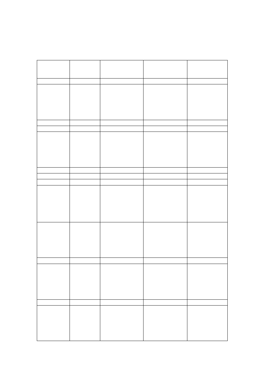
1.4
Specification of coupling
SPECIFICATION OF GEISLINGER COUPLING (BC and BE type)
Number of
Maximum
Maximum
Torsional
Spring Block
Permissible Speed
Permissible Torque
Stiffness
Model
min
-1
{rpm} kNm MNm/rad
41/5/55U 12
3400
10.18 0.142
06 6.3
0.074
07 7.4
0.086
08 8.4
0.098
09 9.5
0.110
10
10.5 0.123
41/7.5/85
12
3400
12.6 0.147
41/7.5/135U 12
3400
7.53
0.0425
48/7.5/3/1 12
2900
17.0
0.147
06 13.8
0.197
07 16.1
0.229
08 18.4
0.262
09 20.7
0.295
10 23.0
0.328
48/10/55U
12
2900
27.6 0.393
48/10/80H 12
2900
29.9
0.284
48/10/80N 12
2900
30.3
0.288
48/10/80U 08
2900
14.8
0.141
06 11.91
0.138
07 13.89
0.160
08 15.88
0.183
09 17.86
0.206
10 19.85
0.229
48/10/85
12
2900
23.82 0.275
06 6.6
0.037
07 7.7
0.043
08 8.8
0.049
09 9.9
0.056
10 11.0
0.062
48/10/140U
12
2900
13.2 0.074
56/12.5/80N 12
2600
52.1
0.495
06 18.7
0.216
07 21.8
0.251
08 24.9
0.287
09 28.1
0.323
10 31.2
0.359
56/12.5/85
12
2600
37.4 0.431
56/12.5/140U 12
2600
24.3
0.137
06 20.3
0.188
07 23.7
0.219
08 27.1
0.251
09 30.5
0.282
10 33.9
0.313
56/15/85U
12
2600
40.7 0.376

- 11 -
Number of
Maximum
Maximum
Torsional
Spring Block
Permissible Speed
Permissible Torque
Stiffness
Model
min
-1
{rpm} kNm MNm/rad
06 14.6
0.082
07 17.1
0.096
08 19.5
0.109
09 21.9
0.123
10 24.4
0.137
56/15/140U
12
2600
29.3 0.164
63/10/175H 10
2300
23.6
0.104
06 15.3
0.085
07 17.9
0.099
08 20.4
0.113
09 23.0
0.128
10 25.5
0.142
63/12.5/140U
12
2300
30.6 0.170
06 34.0
0.483
07 39.6
0.564
08 45.3
0.644
09 50.9
0.725
10 56.6
0.805
63/15/55U
12
2300
67.9 0.966
06 27.9
0.321
07 32.5
0.375
08 37.1
0.429
09 41.8
0.482
10 46.4
0.536
63/15/85
12
2300
55.7 0.643
06 19.3
0.135
07 22.5
0.158
08 25.7
0.181
09 28.9
0.203
10 32.1
0.226
63/15/140
12
2300
38.5 0.271
63/15/140U 12
2300
36.7
0.205
06 39.6
0.565
07 46.2
0.659
08 52.8
0.753
09 59.4
0.848
10 66.0
0.942
63/17.5/55U
12
2300
79.2 1.130
06 21.4
0.120
07 25.0
0.139
08 28.5
0.159
09 32.1
0.179
10 35.6
0.199
63/17.5/140U
12
2300
42.8 0.239
72/15/50N 14
2000
113
1.72
06 23.9
0.133
07 27.9
0.155
08 31.9
0.177
09 35.9
0.200
10 39.8
0.222
72/15/140U
12
2000
47.8 0.266

- 12 -
Number of
Maximum
Maximum
Torsional
Spring Block
Permissible Speed
Permissible Torque
Stiffness
Model
min
-1
{rpm} kNm MNm/rad
72/17.5/50N 14
2000
132
2.01
06 53.2
0.755
07 62.0
0.881
08 70.9
1.007
09 79.8
1.133
10 88.6
1.258
72/17.5/55U
12
2000
106.3 1.510
06 44.1
0.510
07 51.4
0.595
08 58.7
0.680
09 66.1
0.765
10 73.4
0.850
72/17.5/85
12
2000
88.1 1.020
06 40.4
0.374
07 47.1
0.436
08 53.8
0.499
09 60.5
0.561
10 67.3
0.623
72/17.5/85U
12
2000
80.7 0.748
72/20/55U 12
2000
121.4
1.73
10 76.9
0.713
72/20/85U
12
2000
93.6 0.855
06 31.9
0.178
07 37.2
0.207
08 42.5
0.237
09 47.8
0.266
10 53.1
0.296
72/20/140U
12
2000
63.7 0.355
80/17.5/55U 12
1800
124.8
1.77
06 50.60
0.580
07 59.03
0.677
08 67.46
0.773
09 75.89
0.870
10 84.33
0.967
80/17.5/85
12
1800
101.19 1.160
80/20/55U
12
1800
143 2.03
06 38.5
0.217
07 44.9
0.253
08 51.3
0.289
09 57.8
0.325
10 64.2
0.361
80/20/140U
12
1800
77.0 0.433
06 80.0
1.140
07 93.3
1.330
08 106.7
1.520
09 120.0
1.710
10 133.3
1.900
80/22.5/55U
12
1800
160.0 2.280
80/22.5/140U 12
1800
86.6
0.487
- 13 -
Number of
Maximum
Maximum
Torsional
Spring Block
Permissible Speed
Permissible Torque
Stiffness
Model
min
-1
{rpm} kNm MNm/rad
90/20/50N 14
1600
234
3.55
06 94.3
1.35
07 110.0
1.58
08 125.7
1.80
09 141.4
2.03
10 157.1
2.25
90/20/55U
12
1600
188.5 2.70
90/22.5/50U 14
1600
237
3.59
06 86
0.99
07 100
1.16
08 115
1.32
09 129
1.49
10 143
1.65
90/22.5/85
12
1600
172 1.98
06 80.0
0.745
07 93.3
0.869
08 106.6
0.993
09 119.9
1.118
10 133.3
1.242
90/22.5/85U
12
1600
159.9 1.490
06 56.4
0.321
07 65.8
0.374
08 75.2
0.427
09 84.6
0.481
10 94.0
0.534
90/22.5/140U
12
1600
112.8 0.641
90/22.5/200U 08
1600
65.3
0.250
90/25/50U 14
1600
263
3.99
90/25/85 12
1600
187
2.20
06 89.1
0.825
07 103.9
0.963
08 118.7
1.100
09 133.6
1.238
10 148.4
1.375
90/25/85U
12
1600
178.1 1.650
06 62.8
0.356
07 73.2
0.415
08 83.7
0.475
09 94.1
0.534
10 104.6
0.593
90/25/140U
12
1600
125.5 0.712
100/20/80N 12
1300
255
2.42
100/25/50N 14
1300
361
5.47
100/25/50U 14
1300
329
4.98
08 134.9
2.405
10 168.6
3.007
12 202.4
3.608
14 236.1
4.209
100/25/55
16
1300
269.8 4.810
100/25/135N 12
1300
223
1.26
- 14 -
Number of
Maximum
Maximum
Torsional
Spring Block
Permissible Speed
Permissible Torque
Stiffness
Model
min
-1
{rpm} kNm MNm/rad
06 81.3
0.465
07 94.8
0.542
08 108.3
0.619
09 121.9
0.697
10 135.4
0.774
100/25/140U
12
1300
162.5 0.929
06 115.0
1.320
07 134.2
1.540
08 153.3
1.760
09 172.5
1.980
10 191.7
2.200
110/20/85
12
1300
230.0 2.640
110/25/50N 14
1300
439
6.66
110/30/80U 12
1300
328
3.12
110/30/50N 14
1300
527.0
8.010
110/30/50U 14
1300
481.0
7.300
125/22.5/135U 12
1100
216
1.22
06 124.2
0.700
07 144.8
0.817
08 165.5
0.933
09 186.2
1.050
10 206.9
1.167
125/25/140U
12
1100
248.3 1.400
125/25/200U 10
1100
121.0
0.464
125/30/47U 14
1100
705
10.6
125/35/50N 14
1100
802
12.2

- 15 -
SECTION 2
: Installation
2.1 Installation
Tolerance
2.1.1 Tolerance of distance between input and output shaft flanges
Distance (A) between input and output
shaft flanges must be adjusted within the
tolerance as follows ;
A = Installation Length ± 0.5 mm
( This tolerance applies to all models, and
installation length are listed on the name
plate. )
Figure 2-1
2.1.2 Tolerance of center misalignment of input and output shaft
Figure 2-2
2.1.3 Tolerance of angular misalignment of input and output shaft
Tolerance θ applies to all models.
θ
= Less than 0.02 deg.
Figure 2-3
Model
41 48 56 63
Dimension B ±0.11 ±0.12 ±0.15 ±0.17
Model
72 80 90 100
Dimension B ±0.20 ±0.22 ±0.25 ±0.27
Model 110
125
Dimension B ±0.30 ±0.32
- 16 -
2.2
Installation of Geislinger coupling
CAUTION : Be sure to use supporting piece when moving the coupling.
2.2.1 Installation procedure
STEP 1 :Apply grease to the grooves on the face of flange. And then O-rings are
fitted to the grooves.
STEP 2 :Adjustment of Distance between input and output shaft flanges.
According to 2-1-1, Distance between input and output shaft flanges is
adjusted.
STEP 3 :Outer-member of the coupling is fitted to the shaft flange, If Adjustment
is done without the coupling fixing to the shaft flange, Check the
misalignment by STEP 7.
STEP 4
:Setting of the Dial-gauge is shown in Figure 2-4.
(BC type) (BE type)
Figure 2-4
STEP
5 :Turning the shaft flange, which is fitted the Dial-gauge, or
Outer-member of the coupling. Measure center misalignment on outer
circumference (REMARK 1) and angular misalignment on side surface
(REMARK 2). Position of input and output shaft flanges must be settled
so that the deviations are less than the values shown 2-1-1 and 2-1-3.
(REMARK 1) : Tolerance of center misalignment is twice as much as the value of
2-1-2.
(REMARK 2) : Tolerance of angular misalignment is as follows ;
Distance from shaft center to measurement point x 0.0007 mm

- 17 -
STEP 6 :Remove the Dial-gauge and supporting piece, Fix the inner-star flange
to the other flange.
STEP 7 :After fixing the coupling, set the Dial-gauge (shown in Figure 2-4).
Center misalignment and angular misalignment are measured so that to
confirm the deviations are less than the values shown 2-1.
Above procedure is standard installation procedure, but it is estimated that
operating condition is different from primary condition. In that case, it is necessary
installation with consideration of that difference.


- 18 -
SECTION 3
:Operation
During operation, the inside of the coupling is always filled with lubrication oil.
However, after internal inspection, it must be refilled with oil. Also, after long
periods of unused, refilling may be necessary. Fill the coupling with oil according
to the following procedure before operation.
3.1
Lubrication Oil Filling Procedure
STEP 1 :Turn the shaft so that any one of the air vent plugs (21) on the side
plate(cover)(3) comes to the top.
STEP 2 :Remove all air vent plugs (21). ( Remove lock-wire before removing
plugs. )
STEP 3 :This step applies only to closed oil type couplings. Remove the plug (41)
for oil feeding hole located at the outer circumference of the inner star
flange (1).
STEP 4 :Operate priming pump or manual pump and confirm that oil comes out
from the air vent plug hole located at the bottom. Then, fasten the air
vent plug (21) at the bottom with copper packing (22).
STEP 5 :When oil filled the coupling, air bubbles come out with oil from the top
plug hole. Fasten the air vent plug (21) with copper packing (22) after all
bubbles come out.
STEP 6 :This step applies only to closed oil type couplings. Fasten the plug (41)
with copper packing to oil feed hole at inner star flange (1).
Since copper packing (22) are used for air vent plugs (21), attention must be paid
not to use them for wire –lock plugs (20) which are located next to the air vent
plugs (21).

- 19 -
1.0
SECTION 4
:Preventive Maintenance
4.1
Periodical Preventive Maintenance
Table 4-1 shows the standard time for inspection.
Time for Inspection
Items to be Inspected
Before Operation
( In case of operation after long periods of unused.)
・
Vent air inside the coupling as described in
Clause 3-1.
・
For closed oil type:
Check amount of oil by inserting oil level gauge
into oil feed hole located on inner star flange .
Add oil if level is low.
After 1000 Hours
of Operation
(For closed type only)
Replace oil after 1000 hours of operation
Every 2 Years
Disassemble the coupling for inspection and clean
inside according to the maintenance schedule of the
engine. Replace parts if necessary.
But within 2 years, when LO in the coupling would be
predicted inferior quality or abnormal condition was
detected on the coupling. Coupling should be
disassembled and to be inspected inside.
( Table 4-1)
4.2
Inspection Points and Replacement Criteria
4.2.1 Inner Star
Remove inner star and check for abrasion at grooved
part. If it is predicted abrasion will extend deeper than
1.0 mm before the next inspection, replace the inner
star.
Since hardening reaches a depth of only 0.8 - 1.0 mm,
any abrasion beyond this point will progress rapidly.
4.2.2 Flange and Lateral Plate
After removing inner star, check the extend of abrasion where each parts
contact the inner O-ring.
If the abrasion is over 0.5 mm replace the plate.
- 20 -
1.0
Leaf
Shim
4.2.3 Spring Block
Check each lapped leaf for damage. This check can be made by viewing from the
block side after removing the lateral plate.
If damage exists, replace the whole block unless the damage is confirmed to the
end of the longest leaf in the block.
4.2.4 Long Leaf
Check the long leaf for the damage or wear at the
tip after removing the inner star. If it is predicted
that wear will go beyond 1.0 mm before the next
inspection, or if the damage is detected, replace
the long leaf.
The thickness of the long leaf without any wear is
shown in Appendix - 1.
4.2.5 Shim
Check the shim inserted between the leaves of the spring block and replace
them with new ones if they are worn.
4.2.6 Oil Vent Mechanism at the center of Oil Stop Ring
(Applies only to Oil Circulation type)
For oil venting, a plug is used to the type in which oil is fed from the inner star
flange, and a pipe is used on the type in which oil is fed from the Flange.
Check the clearance of the oil-hole shown in Figure 4-1 and Figure 4-2 and
clean them if they are closed by sludge.
Figure 4-1 Figure 4-2
- 21 -
4.2.7 Bolt for Intermediate Piece
These bolts are not removed except when replacing spring block and long leaf,
or for some other special reason. Whenever the coupling is removed, however,
check the bolt for tightness and oil leakage.
4.2.8 O-rings (for inner star and oil stop ring)
Take O-ring out of its groove and check it visually for cracks, tears or damage.
Also measure the dimension of “a” shown in Figure 4-3 and check for fatigue
and wear of the O-ring.
Appendix – 2 shows the replacement criteria, O-rings must be replaced every
two years during regular disassembly and inspection.
Appearance
Replace with new ones if cracks, cuts or tears exist.
Figure 4-3
4.2.9 Other O-rings
Remove O-rings from grooves and check them visually. O-rings must be
replaced when they are cut or if oil leakage is recognized, and also when
disassembly and inspection are carried out every two years.


- 22 -
SECTION 5
:Disassembly
5.1 Disassembly
Prior to disassembly, put marks on parts for re-assembling.
Disassembly work should be done on a floor covered with papers or wooden
plates; special care should be taken not to damage O-rings.
STEP 1
:Loosen coupling bolts of inner star flange.
CAUTION :For the type with oil feed from inner star flange, an oil pan is required
to receive the oil which will come out when the coupling bolts are
loosened.
STEP 2 :Fix the inner star firmly with the outer member by attaching the 2
support pieces (44).
STEP 3 :Loosen all coupling bolts of flanges, and lift up the whole coupling by
crane. Since the total length of the coupling would be shortened 5-10 mm
by fastening the bolts of the support pieces (44), it should be easily
removed.
STEP 4
:Put the coupling down on the floor facing the Flange ( 2)(driving) up.
STEP 5 :This STEP is applied to only oil circulation type models. Loosen and
remove the cover bolts (19).
STEP 6 :Loosen the plug (15) on oil stop ring ( 7). ( For the type in which oil is
feed from inner star. )
STEP 7
:Loosen the oil stop ring bolts (17) and remove it.
Note - If it is not easily removed, use the removed bolts (17) as pulleys
for easy removing.
STEP 8 :Turn the coupling upside-down. (Inner star flange ( 1) faces up.) At this
time, on oil pan is required to receive the lubrication oil which will flow
out.
STEP 9 :Loosen the bolts (45) on support pieces (44) and pull the inner star ( 1)
out gently.
STEP 10 :Loosen all bolts (10) for the intermediate piece, and remove the lateral
plate ( 3) (cover). At this time, put a mark on the bolt-heads and lateral
plate ( 3) (cover) as matching-mark for re-assembly. ( But only if no
torque wrench is available.)

- 23 -
STEP 11 :Loosen the centering bolt (12) by using a hexagonal wrench.
STEP 12 :Clean all disassembled parts with gasoline, kerosene or light oil, and dry
them up. (After cleaning and drying, anticorrosive should be applied.)
CAUTION :As some special tools and facilities are necessary for disassembly of
clamping ring (4), intermediate ring (5), intermediate piece (6), spring
block (8) and intermediate block (13) (hereinafter called ″Complete set
of spring block ″ ), please contact our service stations when it is
necessary to disassembly them.
5.2 Disassembly
lateral
plate
Disassembling lateral plate only on installation coupling to the both flanges
STEP 1
:Put fitting mark lateral plate (3) and clamping ring (4) . In the case of no
torque wrench for bolt (10), tightening mark is also put on the bolt and
lateral plate. Then loosen all bolts (10)
STEP 2 :With hanging lateral plate (3) , take off lateral plate. This time, be
careful not to damage o-ring (25) and inner circumference of lateral plate.
This face and o-ring are important to seal LO of inside coupling.

- 24 -
SECTION 6
:Assembly
6.1 Assembly
STEP 1 :Put the flange (2) horizontally on the floor facing the O-ring groove, and
apply enough grease in O-ring grooves. Then insert O-rings (26).
STEP 2 :Put the complete set of spring block on the flange (2). Set the
identification marks made before disassembling to each other.
STEP
3 :Measure the gap of inner circumference between flange(2) and
intermediate pieces(6) by depth micrometer. Put the complete set of
spring block in such a way that each gaps are same.
STEP 4
: Fasten the bolts(12), fix the complete set of spring block and flange (2).
STEP 5 :Apply enough grease in the O-ring grooves on the lateral plate (cover)
and insert O-ring (26).
STEP 6 :Put the lateral plate (3) on the complete set of spring block and set the
identification marks made before disassembling to each other.
STEP 7 :Fasten 4 bolts (10) with conical spring washers (11) slightly. Measure
the gap of inner circumference between the lateral plate (3) and
intermediate pieces (6) by depth micrometer. Adjust the lateral plate in
such way that each gap is same. Then fasten 4 bolts in order to avoid
moving the lateral plate (3). When tightening these bolts, coat LOCTITE
222 between conical spring washer (11) and bolts(10), and coat LOCTITE
271 between lateral plate (3) and bolts(10). Then fasten all bolts on
standard torque. Tightening torque: see Appendix - 3
STEP 8
: Stand the inner star (1) so that its flange faces down.
Apply grease to O-ring groove and then insert O-ring (25)..
STEP 9
:Fit support pieces (44) to inner star flange.
STEP 10 :Turn the set assembled in STEP 7 upside down ( flange (2) faces up ) and
lift it up. Then, match the marks with those of inner star (1) and put the
assembled set down over the inner star (1) .When the support pieces (44)
reach the lateral plate (3), attach them to each other.
STEP 11 :Apply enough grease to O-ring groove of the oil stop ring (7) , and insert
O-ring (25).
STEP 12 : Put the oil stop ring (7). on the inner star (1) and fasten bolts(17).
STEP 13 : Fasten the plug (15) with copper packing (16) in the center of the oil
stop ring (7). ( But only for the type of which oil is feed from inner star
flange (1). )

- 25 -
STEP 14 : Apply grease to O-ring groove on the cover side of flange (2) and insert
O-ring (29) in the groove.
STEP 15 : Put the cover (9) on gently and fasten it with bolts (19).
Lubrication oil must be filled inside the coupling in accordance with clause 3-1
before re-starting operation.
6.2
Assembly of lateral plate
In the case of disassembling lateral plate only on installation coupling to the both
flanges, Installation procedure is as follows.
STEP 1 :Install lateral plate with tightening 4 bolts(10) slightly. Turn the engine
and measure center misalignment on outer circumference of lateral plate
(3). Center misalignment should be within 0.1mm.
STEP 2 :Tighten all bolts (10) according to standard torque which shows in
Appendix 3. In the case of no torque wrench, tight by tightening mark.

- 26 -
Appendix – 1 Table for thickness of long leaf
Thickness without wears
Thickness of Long Leaf
Thickness of Long Leaf
Model
mm
Model
mm
41/5/55U 4.60
80/17.5/55U
8.30
41/7.5/85 3.70
80/17.5/85
6.40
41/7.5/135U 3.40
80/20/55U 8.30
48/7.5/3/1 4.40
80/20/140U
5.95
48/10/55U 5.40
80/22.5/55U 8.30
48/10/80H 4.70
80/22.5/140U
5.95
48/10/80N 4.70
90/20/50N
14.30
48/10/80U 4.15
90/20/55U 9.55
48/10/85 4.25
90/22.5/50U
10.80
48/10/140U 3.75
90/22.5/85 7.40
56/12.5/80N 5.40
90/22.5/85U 6.50
56/12.5/85 4.65
90/22.5/140U
6.80
56/12.5/140U 4.25 90/22.5/200U
6.45
56/15/85U 4.10
90/25/50U
10.80
56/15/140U 4.25
90/25/85 7.40
63/10/175H 5.05
90/25/85U 6.50
63/12.5/140U 4.75 90/25/140U 6.80
63/15/55U 6.65
100/20/80N
8.85
63/15/85 5.15
100/25/50N
14.30
63/15/140 5.55
100/25/50U
12.00
63/15/140U 4.75
100/25/55 13.40
63/17.5/55U 6.65
100/25/135N
9.05
63/17.5/140U 4.75 100/25/140U 7.70
72/15/50N 10.45
110/20/85 9.10
72/15/140U 5.35
110/25/50N
15.90
72/17.5/50N 10.45
110/30/80U 8.70
72/17.5/55U 7.70
110/30/50N 15.90
72/17.5/85 5.95
110/30/50U
13.20
72/17.5/85U 5.25
125/22.5/135U
10.20
72/20/55U 7.70
125/25/140U
9.50
72/20/85U 5.25
125/25/200U
7.70
72/20/140U 5.35
125/30/47U
17.00
125/35/50N
18.10

- 27 -
Appendix – 2 Table for O-ring dimension
Dimension (a)
Dimension (a)
Model
mm
Model
mm
41/5/55U 9.0
80/17.5/55U
16.2
41/7.5/85 9.0
80/17.5/85
16.2
41/7.5/135U 9.0
80/20/55U 16.2
48/7.5/3/1 10.8
80/20/140U
16.2
48/10/55U 10.8
80/22.5/55U 16.2
48/10/80H 10.8
80/22.5/140U
16.2
48/10/80N 10.8
90/20/50N 18.0
48/10/80U 10.8
90/20/55U 18.0
48/10/85 10.8
90/22.5/50U
18.0
48/10/140U 10.8
90/22.5/85 18.0
56/12.5/80N 12.6
90/22.5/85U 18.0
56/12.5/85 12.6
90/22.5/140U
18.9
56/12.5/140U 12.6 90/22.5/200U
17.1
56/15/85U 12.6
90/25/50U 17.1
56/15/140U 12.6
90/25/85 18.0
63/10/175H 13.5
90/25/85U 18.0
63/12.5/140U 13.5 90/25/140U 18.9
63/15/55U 13.5
100/20/80N
19.8
63/15/85 13.5
100/25/50N
19.8
63/15/140 13.5
100/25/50U
19.8
63/15/140U 13.5
100/25/55 19.8
63/17.5/55U 13.5
100/25/135N
19.8
63/17.5/140U 13.5 100/25/140U 19.8
72/15/50N 15.3
110/20/85 21.6
72/15/140U 15.3
110/25/50N 21.6
72/17.5/50N 15.3
110/30/80U 21.6
72/17.5/55U 15.3
110/30/50N 21.6
72/17.5/85 15.3
110/30/50U
21.6
72/17.5/85U 15.3
125/22.5/135U
24.3
72/20/55U 15.3
125/25/140U
24.3
72/20/85U 15.3
125/25/200U
24.3
72/20/140U 15.3
125/30/47U 24.3
125/35/50N
24.3
Appearance
Replace with new ones if cracks, cuts or tears exist.

Niigata Power System Co., Ltd.
2756-3,Higasiko 5-chome,Seiromachi,Kitakanbara-gun,Niigata 957-0101
Japan
TEL +81-25-256-3515 FAX +81-25-256-3532
Document Outline
- INSTRUCTION MANUAL FOR GEISLINGER COUPLING
- PAGE
- SECTION 1 STRUCTURE
- SECTION 2 INSTALLATION
- 2.1 INSTALLATION TOLERANCE
- 2.2 INSTALLATION OF GEISLINGER COUPLING
- SECTION 3 OPERATION
- SECTION 4 PREVENTIVE MAINTENANCE
- SECTION 5 DISASSEMBLY
- SECTION 6 ASSEMBLY
- APPENDIX-1 TABLE FOR THICKNESS OF LONG LEAF
- APPENDIX-2 TABLE FOR O-RING DIMENSION
- APPENDIX-3 TABLE OF TIGHTENING TORQUE OF THE BOLTS
Wyszukiwarka
Podobne podstrony:
05 Instrukcje warunkoweid 5533 ppt
DJ F1 S1 Instruction Manual
05 Instrukcje Sterujaceid 5708
cw 05 instrukcja id 121376 Nieznany
ONESTER 158 01 05 Instrukcja i Schemat
BSA Instruction Manual D14
05- INSTRUKCJA BHP PRZY OBSŁUDZE PRASY HYDRAULICZNEJ, Instrukcje BHP, VII - ELEKTRYKA
Instruction Manual
05.Instrukcja rozmrazania i mycia urządzeń, Haccp-Dokumentacja-przykład
05 Instrukcje Sterujace
05 Instrukcja montażu AW10
05 MICROLOGIC 2 0 5 0 MANUAL
05 instrukcja dla gracza B, studia kierunek administracja, gra negocjacyjna
05 Instrukcja Geol, Studia- geodezja, Semestr I
KLAMSTER 170 01 05 Instrukcja i Schemat
ICOM instruction manual[1]
05 instrukcja
więcej podobnych podstron