
1
11
11
P4VM890
User Manual
Version 2.1
Published August 2007
Copyright©2007 ASRock INC. All rights reserved.

2
22
22
Copyright Notice:
Copyright Notice:
Copyright Notice:
Copyright Notice:
Copyright Notice:
No part of this manual may be reproduced, transcribed, transmitted, or translated in
any language, in any form or by any means, except duplication of documentation by
the purchaser for backup purpose, without written consent of ASRock Inc.
Products and corporate names appearing in this manual may or may not be regis-
tered trademarks or copyrights of their respective companies, and are used only for
identification or explanation and to the owners’ benefit, without intent to infringe.
Disclaimer:
Disclaimer:
Disclaimer:
Disclaimer:
Disclaimer:
Specifications and information contained in this manual are furnished for informa-
tional use only and subject to change without notice, and should not be constructed
as a commitment by ASRock. ASRock assumes no responsibility for any errors or
omissions that may appear in this manual.
With respect to the contents of this manual, ASRock does not provide warranty of
any kind, either expressed or implied, including but not limited to the implied warran-
ties or conditions of merchantability or fitness for a particular purpose.
In no event shall ASRock, its directors, officers, employees, or agents be liable for
any indirect, special, incidental, or consequential damages (including damages for
loss of profits, loss of business, loss of data, interruption of business and the like),
even if ASRock has been advised of the possibility of such damages arising from any
defect or error in the manual or product.
This device complies with Part 15 of the FCC Rules. Operation is subject to the
following two conditions:
(1) this device may not cause harmful interference, and
(2) this device must accept any interference received, including interference that
may cause undesired operation.
CALIFORNIA, USA ONLY
The Lithium battery adopted on this motherboard contains Perchlorate, a toxic
substance controlled in Perchlorate Best Management Practices (BMP) regulations
passed by the California Legislature. When you discard the Lithium battery in
California, USA, please follow the related regulations in advance.
“Perchlorate Material-special handling may apply, see
www.dtsc.ca.gov/hazardouswaste/perchlorate”
ASRock Website: http://www.asrock.com

3
33
33
Contents
Contents
Contents
Contents
Contents
1. Introduction
1. Introduction
1. Introduction
1. Introduction
1. Introduction ..................................................
..................................................
..................................................
..................................................
.................................................. 5
5
5
5
5
1.1 Package Contents .......................................................... 5
1.2 Specifications ................................................................ 6
1.3 Motherboard Layout ...................................................... 9
1.4 ASRock 6CH I/O Plus
TM
....................................................................................
10
2. Installation
2. Installation
2. Installation
2. Installation
2. Installation ....................................................
....................................................
....................................................
....................................................
.................................................... 11
11
11
11
11
Pre-installation Precautions ................................................... 11
2.1 CPU Installation .............................................................. 12
2.2 Installation of CPU Fan and Heatsink ............................ 12
2.3 Installation of Memory Modules (DIMM) ......................... 13
2.4 Expansion Slots (PCI, AMR, and PCI Express Slots) .... 14
2.5 Jumpers Setup .............................................................. 15
2.6 Onboard Headers and Connectors .............................. 16
2.7 Serial ATA (SATA) Hard Disks Installation ..................... 19
2.8 Hot Plug and Hot Swap Functions for SATA HDDs ....... 19
2.9 SATA HDD Hot Plug Feature and Operation Guide ........ 20
2.10 Driver Installation Guide ................................................. 22
2.11 AMR Card and Driver Installation ................................... 22
2.12 Installing Windows
®
2000 / XP With RAID Functions .... 22
2.13 Installing Windows
®
2000 / XP Without RAID
Functions ....................................................................... 23
2.14 Untied Overclocking Technology ................................... 24
3. BIOS S
3. BIOS S
3. BIOS S
3. BIOS S
3. BIOS SETUP UTILITY
ETUP UTILITY
ETUP UTILITY
ETUP UTILITY
ETUP UTILITY .........................................
.........................................
.........................................
.........................................
......................................... 25
25
25
25
25
3.1 Introduction .................................................................... 25
3.1.1 BIOS Menu Bar .................................................... 25
3.1.2 Navigation Keys ................................................... 26
3.2 Main Screen ................................................................... 26
3.3 Advanced Screen ......................................................... 27
3.3.1 CPU Configuration ................................................ 27
3.3.2 Chipset Configuration .......................................... 29
3.3.3 ACPI Configuration ............................................... 32
3.3.4 IDE Configuration ................................................. 33
3.3.5 PCIPnP Configuration ........................................... 35
3.3.6 Floppy Configuration ........................................... 35
3.3.7 Super IO Configuration ........................................ 36
3.3.8 USB Configuration ............................................... 37
3.4 Hardware Health Event Monitoring Screen .................. 38

4
44
44
3.5 Boot Screen ................................................................... 38
3.5.1 Boot Settings Configuration .................................. 39
3.6 Security Screen ............................................................ 39
3.7 Exit Screen .................................................................... 40
4. Software Support
4. Software Support
4. Software Support
4. Software Support
4. Software Support ..........................................
..........................................
..........................................
..........................................
.......................................... 41
41
41
41
41
4.1 Install Operating System ............................................... 41
4.2 Support CD Information ................................................. 41
4.2.1 Running Support CD ............................................ 41
4.2.2 Drivers Menu ........................................................ 41
4.2.3 Utilities Menu ........................................................ 41
4.2.4 Contact Information .............................................. 41

5
55
55
1.
1.
1.
1.
1. Introduction
Introduction
Introduction
Introduction
Introduction
Thank you for purchasing ASRock P4VM890 motherboard, a reliable motherboard
produced under ASRock’s consistently stringent quality control. It delivers excellent
performance with robust design conforming to ASRock’s commitment to quality and
endurance.
In this manual, chapter 1 and 2 contain introduction of the motherboard and step-by-
step guide to the hardware installation. Chapter 3 and 4 contain the configuration
guide to BIOS setup and information of the Support CD.
Because the motherboard specifications and the BIOS software might be
updated, the content of this manual will be subject to change without
notice. In case any modifications of this manual occur, the updated
version will be available on ASRock website without further notice. You
may find the latest VGA cards and CPU support lists on ASRock website
as well. ASRock website http://www.asrock.com
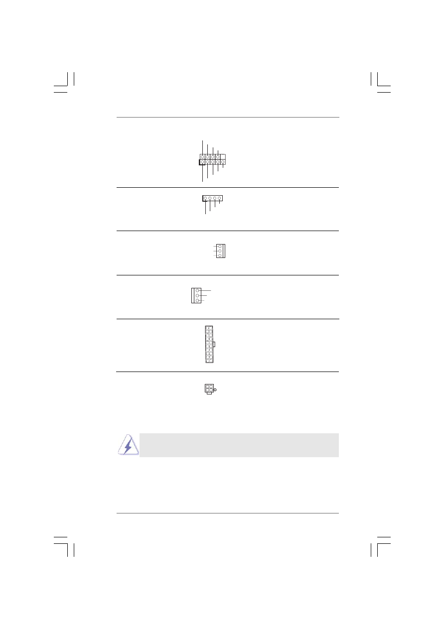
1.1 Package Contents
1.1 Package Contents
1.1 Package Contents
1.1 Package Contents
1.1 Package Contents
ASRock P4VM890 Motherboard
(Micro ATX Form Factor: 9.6-in x 8.0-in, 24.4 cm x 20.3 cm)
ASRock P4VM890 Quick Installation Guide
ASRock P4VM890 Support CD
One 80-conductor Ultra ATA 66/100/133 IDE Ribbon Cable
One Ribbon Cable for a 3.5-in Floppy Drive
One Serial ATA (SATA) Cable (Optional)
One Serial ATA (SATA) HDD Power Cable (Optional)
One ASRock 6CH I/O Plus
TM
Shield
6
66
66
1.2
1.2
1.2
1.2
1.2
Specifications
Specifications
Specifications
Specifications
Specifications
Platform
- Micro ATX Form Factor: 9.6-in x 8.0-in, 24.4 cm x 20.3 cm
CPU
- Socket 478 for Intel
®
Pentium
®
4 / Celeron
®
D (Prescott,
Northwood, Willamate) processors
- FSB 800/533/400 MHz
- Supports Hyper-Threading Technology (see CAUTION 1)
- Supports Untied Overclocking Technology (see CAUTION 2)
Chipset
- Northbridge: VIA
®
P4M890
- Southbridge: VIA
®
VT8237R Plus
Memory
- 2 x DDR DIMM slots
- Support DDR400/333
- Max. capacity: 2GB
Hybrid Booster
- CPU Frequency Stepless Control (see CAUTION 3)
- ASRock U-COP (see CAUTION 4)
- Boot Failure Guard (B.F.G.)
Expansion Slot
- 3 x PCI slots
- 1 x PCI Express x16 slot
- 1 x AMR slot
Graphics
- Integrated VIA
®
UniChrome Pro 3D/2D Graphics
- DirectX 7.0 VGA
- Max. shared memory 64MB
Audio
- Realtek ALC653 5.1channel AC’97 audio codec
LAN
- VIA
®
PHY VT6103
- Speed: 10/100 Ethernet
- Supports Wake-On-LAN
Rear Panel I/O
ASRock 6CH I/O Plus
TM
- 1 x PS/2 Mouse Port
- 1 x PS/2 Keyboard Port
- 1 x Serial Port: COM1
- 1 x VGA Port
- 1 x Parallel Port (ECP/EPP Support)
- 6 x Ready-to-Use USB 2.0 Ports
- 1 x RJ-45 LAN Port
- Audio Jack: Line in/Front Speaker/Microphone
Connector
- 2 x Serial ATA 1.5 Gb/s connectors, support RAID (RAID 0,
RAID 1 and JBOD) and “Hot Plug” functions
- 2 x ATA133 IDE connectors (support 4 x IDE devices)
- 1 x Floppy connector
- 1 x IR header
- CPU/Chassis FAN connector
7
77
77
- 20 pin ATX power connector
- 4 pin 12V power connector
- CD in header
- AUX in header
- Front panel audio connector
- 2 x USB 2.0 headers (support 4 USB 2.0 ports; 2 of them are
shared with USB45 ports on the I/O panel)
(see CAUTION 5)
BIOS Feature
- 4Mb AMI BIOS
- AMI Legal BIOS
- Supports “Plug and Play”
- ACPI 1.1 Compliance Wake Up Events
- Supports jumperfree
- AMBIOS 2.3.1 Support
Support CD
- Drivers, Utilities, AntiVirus Software (Trial Version)
Hardware
- CPU Temperature Sensing
Monitor
- Chassis Temperature Sensing
- CPU Fan Tachometer
- Chassis Fan Tachometer
- Voltage Monitoring: +12V, +5V, +3.3V, Vcore
OS
- Microsoft
®
Windows
®
2000 / XP compliant
Certifications
- FCC, CE, WHQL
WARNING
Please realize that there is a certain risk involved with overclocking, including adjusting
the setting in the BIOS, applying Untied Overclocking Technology, or using the third-
party overclocking tools. Overclocking may affect your system stability, or even
cause damage to the components and devices of your system. It should be done at
your own risk and expense. We are not responsible for possible damage caused by
overclocking.

8
88
88
CAUTION!
1.
About the setting of “Hyper Threading Technology”, please check page 28.
2.
This motherboard supports Untied Overclocking Technology. Please read
“Untied Overclocking Technology” on page 24 for details.
3.
Although this motherboard offers stepless control, it is not recommended
to perform over-clocking. Frequencies other than the recommended CPU
bus frequencies may cause the instability of the system or damage the
CPU.
4.
While CPU overheat is detected, the system will automatically shutdown.
Before you resume the system, please check if the CPU fan on the
motherboard functions properly and unplug the power cord, then plug it
back again. To improve heat dissipation, remember to spray thermal
grease between the CPU and the heatsink when you install the PC system.
5.
Power Management for USB 2.0 works fine under Microsoft
®
Windows
®
XP
SP1 or SP2 / 2000 SP4.
9
99
99
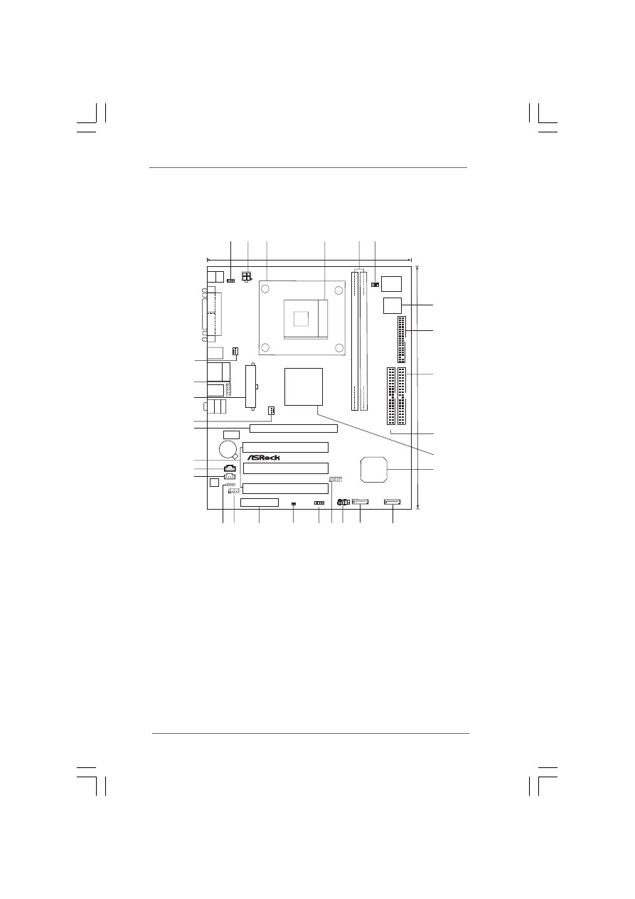
1.3 Motherboard Layout
1.3 Motherboard Layout
1.3 Motherboard Layout
1.3 Motherboard Layout
1.3 Motherboard Layout
DDR1
(64/72
bit,
184-pin
module)
DDR2
(64/72
b
it,
1
84-pin
m
odule)
PCIE1
ATX12V1
SATA2
CLRCMOS1
AUX1
CD1
PCI 1
4Mb
BIOS
Super
I/O
IR1
1
PANEL 1
HDLED RESET
PLED PWRBTN
1
PS2_USB_PWR1
1
P4VM890
VIA
VT8237R
Plus
SPEAKER1
1
FLOPPY1
CMOS
Battery
ATA133
DDR400
VIA
P4M890
Chipset
PGA478
IDE1 IDE2
1
AUDIO1
Audio
CODEC
CHA_F
AN1
A
T
XPWR1
JR1 JL1
LAN
PHY
USB2.0
24.4cm
(9.6
in)
6
4
5
7
18
8
9
23
10
20.3cm (8.0 in)
3
19
1
2
11
12
13
14
15
16
17
22
21 20
24
USB4_5
25
26
27
28
29
PCI 2
PCI 3
FSB800
AMR1
5.1CH
1
USB67
1
SATA1
CPU_F
A
N1
RoHS
RAID
PCI
EXPRESS
USB 2.0
T: USB2
B: USB3
USB 2.0
T: USB0
B: USB1
Top:
RJ-45
P
A
RALLEL
P
ORT
COM1
PS2
Mouse
PS2
Keyboard
VGA1
Top:
Line
In
Center:
Line
Out
Bottom:
Mic
In
USB 2.0
T: USB4
B: USB5
1
PS2_USB_PWR1 Jumper
16
USB 2.0 Header (USB67, Blue)
2
ATX 12V Connector (ATX12V1)
17
Chassis Speaker Header (SPEAKER 1)
3
CPU Heatsink Retention Module
18
Clear CMOS Jumper (CLRCMOS1)
4
CPU Socket
19
AMR Slot (AMR1)
5
2 x 184-pin DDR DIMM Slots (DDR1, DDR2; Blue)
20
Front Panel Audio Header (AUDIO1)
6
Infrared Module Header (IR1)
21
JR1 / JL1 Jumpers
7
Flash Memory
22
Internal Audio Connector: AUX1 (White)
8
Floppy Connector (FLOPPY1)
23
Internal Audio Connector: CD1 (Black)
9
Secondary IDE Connector (IDE2, Black)
24
3 x PCI Slots (PCI1- 3)
10
Primary IDE Connector (IDE1, Blue)
25
PCI Express x16 Slot (PCIE1)
11
North Bridge Controller
26
Chassis Fan Connector (CHA_FAN1)
12
South Bridge Controller
27
ATX Power Connector (ATXPWR1)
13
Primary Serial ATA Connector (SATA1)
28
Shared USB 2.0 Header (USB4_5, Blue)
14
Secondary Serial ATA Connector (SATA2)
29
CPU Fan Connector (CPU_FAN1)
15
System Panel Header (PANEL1)
1 0
1 0
1 0
1 0
1 0
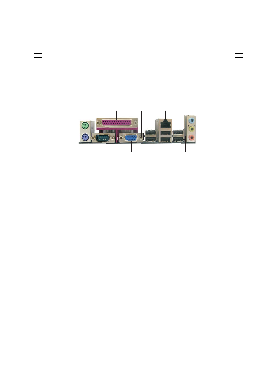
1.4 ASRock 6CH I/O Plus
1.4 ASRock 6CH I/O Plus
1.4 ASRock 6CH I/O Plus
1.4 ASRock 6CH I/O Plus
1.4 ASRock 6CH I/O Plus
TM
TM
TM
TM
TM
1
PS/2 Mouse Port (Green)
7
PS/2 Keyboard Port (Purple)
2
Parallel Port
8
Shared USB 2.0 Ports (USB45)
3
USB 2.0 Ports (USB23)
9
USB 2.0 Ports (USB01)
4
RJ-45 Port
10
VGA Port
5
Line In (Light Blue)
11
COM Port
6
PS/2 Mouse Port (Green)
12
PS/2 Keyboard Port (Purple)
6
7
1
2
4
3
5
8
9
10
11
12

1 1
1 1
1 1
1 1
1 1
2.
2.
2.
2.
2. Installation
Installation
Installation
Installation
Installation
P4VM890 is a Micro ATX form factor (9.6-in x 8.0-in, 24.4 cm x 20.3 cm) motherboard.
Before you install the motherboard, study the configuration of your chassis to en-
sure that the motherboard fits into it.
Pre-installation Precautions
Pre-installation Precautions
Pre-installation Precautions
Pre-installation Precautions
Pre-installation Precautions
Take note of the following precautions before you install motherboard com-
ponents or change any motherboard settings.
1.
Unplug the power cord from the wall socket before touching any
component.
2.
To avoid damaging the motherboard components due to static electricity,
NEVER place your motherboard directly on the carpet or the like. Also
remember to use a grounded wrist strap or touch a safety grounded
object before you handle components.
3.
Hold components by the edges and do not touch the ICs.
4.
Whenever you uninstall any component, place it on a grounded anti-
static pad or in the bag that comes with the component.
Before you install or remove any component, ensure that the power is
switched off or the power cord is detached from the power supply.
Failure to do so may cause severe damage to the motherboard,
peripherals, and/or components.
1 2
1 2
1 2
1 2
1 2
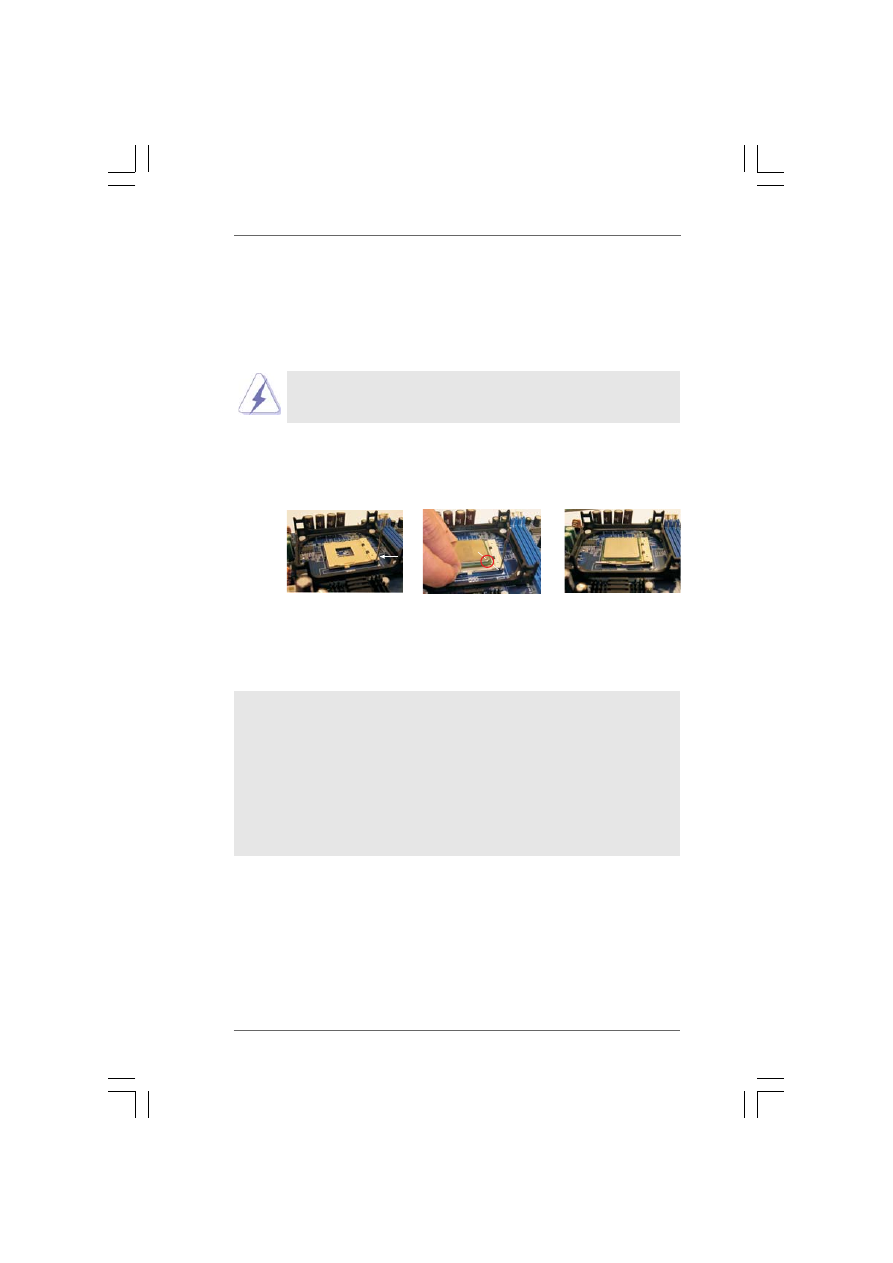
2.1 CPU Installation
2.1 CPU Installation
2.1 CPU Installation
2.1 CPU Installation
2.1 CPU Installation
Step 1.
Unlock the socket by lifting the lever up to a 90° angle.
Step 2.
Position the CPU directly above the socket such that its marked corner
matches the base of the socket lever.
Step 3.
Carefully insert the CPU into the socket until it fits in place.
The CPU fits only in one correct orientation. DO NOT force the
CPU into the socket to avoid bending of the pins.
Step 4.
When the CPU is in place, press it firmly on the socket while you push down
the socket lever to secure the CPU. The lever clicks on the side tab to
indicate that it is locked.
2.2 Installation of CPU Fan and Heatsink
2.2 Installation of CPU Fan and Heatsink
2.2 Installation of CPU Fan and Heatsink
2.2 Installation of CPU Fan and Heatsink
2.2 Installation of CPU Fan and Heatsink
This motherboard adopts 478-pin CPU socket to support Intel
®
Pentium
®
4
/
Celeron
®
CPU. It requires larger heatsink and cooling fan to dissipate heat.
You also need to spray thermal grease between the CPU and the heatsink to
improve heat dissipation. Make sure that the CPU and the heatsink are se-
curely fastened and in good contact with each other. Then connect the CPU
fan to the CPU_FAN connector (CPU_FAN1, see p.9 No. 29). For proper
installation, please kindly refer to the instruction manuals of the CPU fan and
the heatsink.
STEP 1:
Lift The Socket Lever Up to 90°
STEP 2/STEP 3:
Match The CPU Marked Corner
to The Socket Marked Corner
STEP 4:
Push Down And Lock
The Socket Lever
Lift Lever Up to 90°
CPU Marked Corner
Socket Marked Corner
1 3
1 3
1 3
1 3
1 3
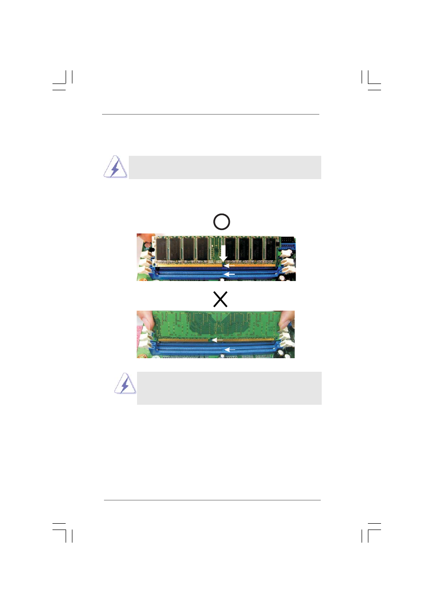
2.3 Installation of Memory Modules (DIMM)
2.3 Installation of Memory Modules (DIMM)
2.3 Installation of Memory Modules (DIMM)
2.3 Installation of Memory Modules (DIMM)
2.3 Installation of Memory Modules (DIMM)
P4VM890 motherboard provides two 184-pin DDR (Double Data Rate) DIMM slots.
Please make sure to disconnect power supply before adding or removing
DIMMs or the system components.
Step 1.
Unlock a DIMM slot by pressing the retaining clips outward.
Step 2.
Align a DIMM on the slot such that the notch on the DIMM matches the break
on the slot.
The DIMM only fits in one correct orientation. It will cause
permanent damage to the motherboard and the DIMM if you
force the DIMM into the slot at incorrect orientation.
Step 3.
Firmly insert the DIMM into the slot until the retaining clips at both ends fully
snap back in place and the DIMM is properly seated.
notch
break
notch
break

1 4
1 4
1 4
1 4
1 4
2.4 Expansion Slots (PCI, AMR and PCI Express Slots)
2.4 Expansion Slots (PCI, AMR and PCI Express Slots)
2.4 Expansion Slots (PCI, AMR and PCI Express Slots)
2.4 Expansion Slots (PCI, AMR and PCI Express Slots)
2.4 Expansion Slots (PCI, AMR and PCI Express Slots)
There are 3 PCI slots, 1 AMR slot, and 1 PCI Express slot on this motherboard.
PCI slots: PCI slots are used to install expansion cards that have the 32-bit PCI
interface.
AMR slot: The AMR slot is used to insert an ASRock MR card with v.92 Modem
functionality.
PCIE Slots: PCIE1 (PCIE x16 slot) is used for PCI Express cards with x16 lane
width graphics cards.
Installing an expansion card
Installing an expansion card
Installing an expansion card
Installing an expansion card
Installing an expansion card
Step 1.
Before installing the expansion card, please make sure that the power
supply is switched off or the power cord is unplugged. Please read the
documentation of the expansion card and make necessary hardware
settings for the card before you start the installation.
Step 2.
Remove the system unit cover (if your motherboard is already installed in a
chassis).
Step 3.
Remove the bracket facing the slot that you intend to use. Keep the screws
for later use.
Step 4.
Align the card connector with the slot and press firmly until the card is
completely seated on the slot.
Step 5.
Fasten the card to the chassis with screws.
Step 6.
Replace the system cover.
1 5
1 5
1 5
1 5
1 5
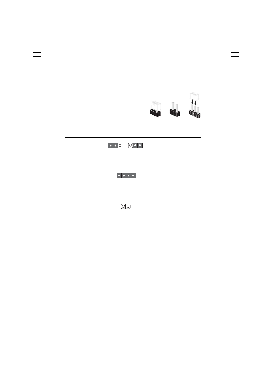
2.5 Jumpers Setup
2.5 Jumpers Setup
2.5 Jumpers Setup
2.5 Jumpers Setup
2.5 Jumpers Setup
The illustration shows how jumpers are
setup. When the jumper cap is placed on
pins, the jumper is “Short”. If no jumper cap
is placed on pins, the jumper is “Open”. The
illustration shows a 3-pin jumper whose pin1
and pin2 are “Short” when jumper cap is
placed on these 2 pins.
Jumper
Setting
PS2_USB_PWR1
Short pin2, pin3 to enable
(see p.9, No. 1)
+5VSB (standby) for PS/2
or USB wake up events.
Note: To select +5VSB, it requires 2 Amp and higher standby current provided
by power supply.
JR1
(see p.9, No. 21)
JL1
(see p.9, No. 21)
Note: If the jumpers JL1 and JR1 are short, both the front panel and the rear panel
audio connectors can work.
Clear CMOS
(CLRCMOS1, 2-pin jumper)
(see p.9, No. 18)
Note: CLRCMOS1 allows you to clear the data in CMOS. The data in CMOS includes
system setup information such as system password, date, time, and system
setup parameters. To clear and reset the system parameters to default setup,
please turn off the computer and unplug the power cord from the power
supply. After waiting for 15 seconds, use a jumper cap to short 2 pins on
CLRCMOS1 for 5 seconds.
+5V
1_2
+5VSB
2_3
Short
Open
JR1
JL1
2-pin jumper
1 6
1 6
1 6
1 6
1 6
2.6 Onboard Headers and Connectors
2.6 Onboard Headers and Connectors
2.6 Onboard Headers and Connectors
2.6 Onboard Headers and Connectors
2.6 Onboard Headers and Connectors
Onboard headers and connectors are NOT jumpers. Do NOT place jumper
caps over these headers and connectors. Placing jumper caps over the
headers and connectors will cause permanent damage of the motherboard!
FDD Connector
(33-pin FLOPPY1)
(see p.9, No. 8)
Note: Make sure the red-striped side of the cable is plugged into Pin1 side of the
connector.
Primary IDE Connector (Blue)
Secondary IDE Connector (Black)
(39-pin IDE1, see p.9, No. 10)
(39-pin IDE2, see p.9, No. 9)
Note: If you use only one IDE device on this motherboard, please set the IDE
device as “Master”. Please refer to the instruction of your IDE device vendor
for the details. Besides, to optimize compatibility and performance, please
connect your hard disk drive to the primary IDE connector (IDE1, blue) and
CD-ROM to the secondary IDE connector (IDE2, black).
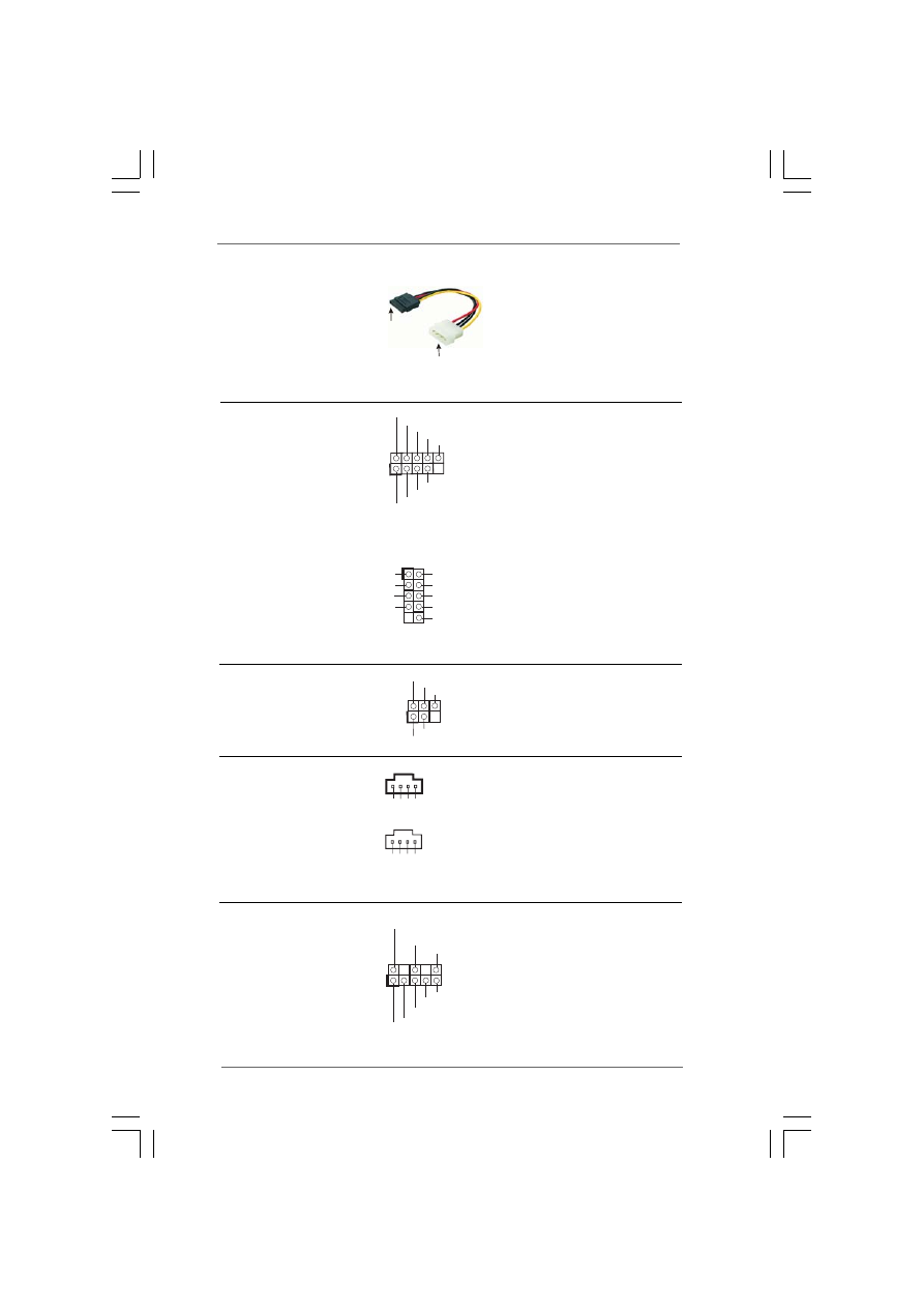
Serial ATA Connectors
These two Serial ATA (SATA)
(SATA1: see p.9, No. 13)
connectors support SATA data
(SATA2: see p.9, No. 14)
cables for internal storage
devices. The current SATA
interface allows up to 1.5 Gb/s
data transfer rate.
Serial ATA (SATA)
Either end of the SATA data
Data Cable
cable can be connected to the
(Optional)
SATA hard disk or the SATA
connector on the motherboard.
FLOPPY1
Pin1
IDE1
PIN1
IDE2
PIN1
connect the black end
to the IDE devices
connect the blue end
to the motherboard
80-conductor ATA 66/100/133 cable
the red-striped side to Pin1
SATA1
SATA2
1 7
1 7
1 7
1 7
1 7
Serial ATA (SATA)
Please connect the black end of
Power Cable
SATA power cable to the power
(Optional)
connector on the drive. Then
connect the white end of SATA
power cable to the power
connector of the power supply.
USB 2.0 Header
Besides six default USB 2.0
(9-pin USB67)
ports on the I/O panel, there are
(see p.9, No. 16)
two USB 2.0 headers on this
motherboard. Each USB 2.0
header can support two USB
2.0 ports. The shared USB 2.0
header (USB4_5) is shared with
Shared USB 2.0 Header
USB ports 45 on the I/O panel.
(9-pin USB4_5)
When using the front panel USB
(see p.9, No. 28)
ports by attaching the front panel
USB cable to USB4_5 header,
the USB ports 45 on the I/O panel
will not be able to function.
Infrared Module Header
This header supports an optional
(5-pin IR1)
wireless transmitting and
(see p.9, No. 6)
receiving infrared module.
Internal Audio Connectors
These connectors allow you
(4-pin CD1, 4-pin AUX1)
to receive stereo audio input
(CD1: see p.9, No. 23)
from sound sources such as
(AUX1: see p.9, No. 22)
a CD-ROM, DVD-ROM, TV
tuner card, or MPEG card.
Front Panel Audio Header
This is an interface for the front
(8-pin AUDIO1)
panel audio cable that allows
(see p.9, No. 20)
convenient connection and
control of audio devices.
DUMMY
GND
+5V
IRTX
IRRX
1
USB_PWR
USB_PWR
P+7
P-7
P+6
P-6
GND
GND
DUMMY
1
connect to the SATA HDD
power connector
connect to the
power supply
USB_PWR
1
P-5
GND
DUMMY
USB_PWR
P+5
GND
P-4
P+4
GND
AUD-OUT-L
1
BACKOUT-R
GND
AUD-OUT-R
MIC-POWER
MIC
BACKOUT-L
CD
-L
GN
D
GN
D
CD
-R
A
UX-
L
GN
D
GN
D
A
UX-
R
CD1
AUX1
1 8
1 8
1 8
1 8
1 8
System Panel Header
This header accommodates
(9-pin PANEL1)
several system front panel
(see p.9, No. 15)
functions.
Chassis Speaker Header
Please connect the chassis
(4-pin SPEAKER 1)
speaker to this header.
(see p.9, No. 17)
Chassis Fan Connector
Please connect the chassis fan
(3-pin CHA_FAN1)
cable to this connector and
(see p.9, No. 26)
match the black wire to the
ground pin.
CPU Fan Connector
Please connect the CPU fan
(3-pin CPU_FAN1)
cable to this connector and
(see p.9, No. 29)
match the black wire to the
ground pin.
ATX Power Connector
Please connect an ATX power
(20-pin ATXPWR1)
supply to this connector.
(see p.9, No. 27)
ATX 12V Connector
Please note that it is necessary
(4-pin ATX12V1)
to connect a power supply with
(see p.9, No. 2)
ATX 12V plug to this connector
so that it can provides sufficient
power. Failing to do so will cause
the failure to power up.
GND
PWRBTN#
PLED-
PLED+
DUMMY
RESET#
GND
HDLED+
HDLED-
1
+5V
DUMMY
DUMMY
SPEAKER
1
GND
+12V
CHA_FAN_SPEED
Please install the heatsink and the CPU fan before installing ATX 12V
connector; otherwise, it may cause permanent damage!
CPU_FAN_SPEED
GND
+12V

1 9
1 9
1 9
1 9
1 9
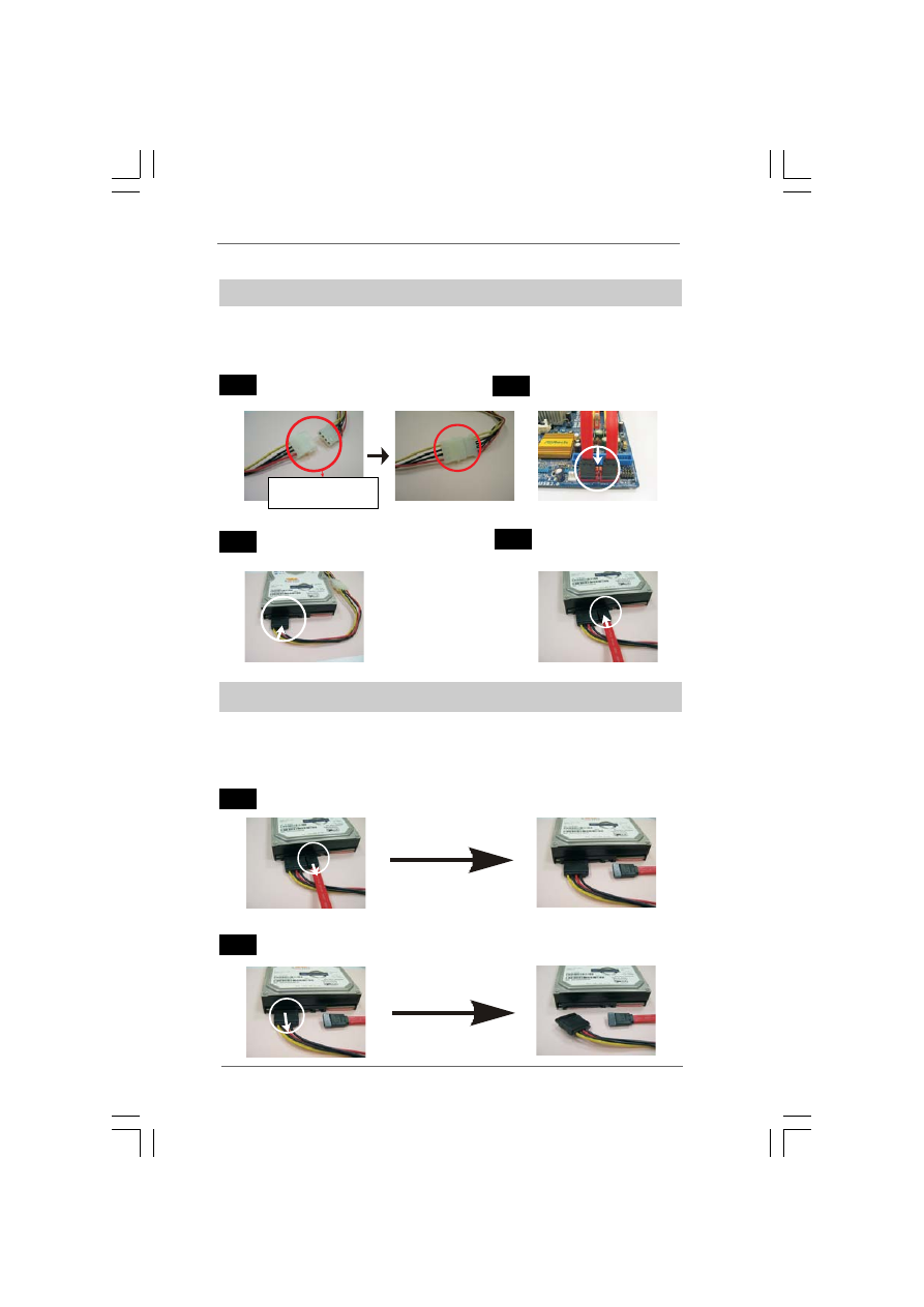
2.7 Serial A
2.7 Serial A
2.7 Serial A
2.7 Serial A
2.7 Serial ATTTTTA (SA
A (SA
A (SA
A (SA
A (SATTTTTA) Hard Disks Installation
A) Hard Disks Installation
A) Hard Disks Installation
A) Hard Disks Installation
A) Hard Disks Installation
This motherboard adopts VIA
®
VT8237R Plus southbridge chipset that supports
Serial ATA (SATA) hard disks and RAID (RAID 0, RAID 1 and JBOD) functions. You
may install SATA hard disks on this motherboard for internal storage devices. This
section will guide you to install the SATA hard disks.
STEP 1: Install the SATA hard disks into the drive bays of your chassis.
STEP 2: Connect the SATA power cable to the SATA hard disk.
STEP 3: Connect one end of the SATA data cable to the motherboard’s SATA
connector.
STEP 4: Connect the other end of the SATA data cable to the SATA hard disk.
2.8 Hot Plug and Hot Swap F
2.8 Hot Plug and Hot Swap F
2.8 Hot Plug and Hot Swap F
2.8 Hot Plug and Hot Swap F
2.8 Hot Plug and Hot Swap Functions for SA
unctions for SA
unctions for SA
unctions for SA
unctions for SATTTTTA HDDs
A HDDs
A HDDs
A HDDs
A HDDs
P4VM890 motherboard supports Hot Plug and Hot Swap functions for
SATA Devices.
NOTE
What is Hot Plug Function?
If the SATA HDDs are NOT set for RAID configuration, it is called “Hot
Plug” for the action to insert and remove the SATA HDDs while the system
is still power-on and in working condition.
However, please note that it cannot perform Hot Plug if the OS has been
installed into the SATA HDD.
What is Hot Swap Function?
If SATA HDDs are built as RAID1 then it is called “Hot Swap” for the action
to insert and remove the SATA HDDs while the system is still power-on
and in working condition.
2 0
2 0
2 0
2 0
2 0
Caution
1. Without SATA 15-pin power connector interface, the SATA Hot Plug cannot be
processed.
2. Even some SATA HDDs provide both SATA 15-pin power connector and IDE
1x4-pin conventional power connector interfaces, the IDE 1x4-pin conventional
power connector interface is definitely not able to support Hot Plug and will
cause the HDD damage and data loss.
Points of attention, before you process the Hot Plug:
1. Below operation procedure is designed only for our motherboard, which
supports SATA HDD Hot Plug.
* The SATA Hot Plug feature might not be supported by the chipset because of
its limitation, the SATA Hot Plug support information of our motherboard is
indicated in the product spec on our website: www.asrock.com
2. Make sure your SATA HDD can support Hot Plug function from your dealer or
HDD user manual. The SATA HDD, which cannot support Hot Plug function, will
be damaged under the Hot Plug operation.
3. Please make sure the SATA driver is installed into system properly. The latest
SATA driver is available on our support website: www.asrock.com
4. Make sure to use the SATA power cable & data cable, which are from our
motherboard package.
5. Please follow below instructions step by step to reduce the risk of HDD crash
or data loss.
The SATA 15-pin power
connector (Black) connect
to SATA HDD
SATA 7-pin
connector
1x4-pin conventional
power connector (White)
connect to power supply
A. SATA data cable (Red) B. SATA power cable
2.9 SA
2.9 SA
2.9 SA
2.9 SA
2.9 SATTTTTA HDD Hot Plug F
A HDD Hot Plug F
A HDD Hot Plug F
A HDD Hot Plug F
A HDD Hot Plug Feature and Operation Guide
eature and Operation Guide
eature and Operation Guide
eature and Operation Guide
eature and Operation Guide
This motherboard supports Hot Plug feature for SATA HDD. Please read below
operation guide of SATA HDD Hot Plug feature carefully. Before you process the
SATA HDD Hot Plug, please check below cable accessories from the motherboard
gift box pack.
A. 7-pin SATA data cable
B. SATA power cable with SATA 15-pin power connector interface
2 1
2 1
2 1
2 1
2 1
How to Hot Plug a SATA HDD:
Points of attention, before you process the Hot Plug:
Please do follow below instruction sequence to process the Hot Plug, improper
procedure will cause the SATA HDD damage and data loss.
Connect SATA data cable to
the motherboard’s SATA connector.
Connect SATA 15-pin power cable connector
(Black) end to SATA HDD.
Connect SATA data cable to
the SATA HDD.
How to Hot Unplug a SATA HDD:
Points of attention, before you process the Hot Unplug:
Please do follow below instruction sequence to process the Hot Unplug, improper
procedure will cause the SATA HDD damage and data loss.
Unplug SATA data cable from SATA HDD side.
Unplug SATA 15-pin power cable connector (Black) from SATA HDD side.
Please connect SATA power cable 1x4-pin end
(White) to the power supply 1x4-pin cable.
Step 1
Step 2
Step 3
Step 4
Step 1
Step 2
SATA power cable 1x4-pin
power connector (White)

2 2
2 2
2 2
2 2
2 2
2.12
2.12
2.12
2.12
2.12 Installing Windows
Installing Windows
Installing Windows
Installing Windows
Installing Windows
®
2000 / XP With RAID Functions
2000 / XP With RAID Functions
2000 / XP With RAID Functions
2000 / XP With RAID Functions
2000 / XP With RAID Functions
If you want to install Windows
®
2000 / Windows
®
XP OS on your SATA
HDDs with RAID functions, please follow below steps.
STEP 1: Set up BIOS.
A.
Enter BIOS SETUP UTILITY
Advanced screen
IDE Configuration.
B.
Set the “SATA Operation Mode” option to [RAID].
STEP 2: Make a SATA driver diskette.
A.
Insert the ASRock Support CD into your optical drive to boot your system.
B.
During POST at the beginning of system boot-up, press <F11> key, and
then a window for boot devices selection appears. Please select CD-
ROM as the boot device.
C.
When you see the message on the screen, “Generate Serial ATA driver
diskette [YN]?”, press <Y>.
D.
Then you will see these messages,
Please insert a blank
formatted diskette into floppy
drive A:
press any key to start
Please insert a floppy diskette into the floppy drive, and press any key.
E.
The system will start to format the floppy diskette and copy SATA drivers
into the floppy diskette.
2.10
2.10
2.10
2.10
2.10 Driver Installation Guide
Driver Installation Guide
Driver Installation Guide
Driver Installation Guide
Driver Installation Guide
To install the drivers to your system, please insert the support CD to your optical
drive first. Then, the drivers compatible to your system can be auto-detected and
listed on the support CD driver page. Please follow the order from up to bottom
side to install those required drivers. Therefore, the drivers you install can work
properly.
2.11
2.11
2.11
2.11
2.11 AMR Card and Driver Installation
AMR Card and Driver Installation
AMR Card and Driver Installation
AMR Card and Driver Installation
AMR Card and Driver Installation
If you do not insert AMR card to this motherboard, and you finish installing all
drivers to your system now, but in the future, you plan to use AMR card function
on this motherboard, please follow the steps below then.
1. Insert AMR card to AMR slot on this motherboard. Please make sure that the
AMR card is completely seated on the slot.
2. Install AMR card driver from our support CD to your system.
3. Reboot your system.

2 3
2 3
2 3
2 3
2 3
If you want to use “VIA RAID Tool” in Windows
®
environment, please install
SATA drivers from the Support CD again so that “VIA RAID Tool” will be
installed to your system as well.
NOTE. If you install Windows
®
2000 / Windows
®
XP on IDE HDDs and want to manage
(create, convert, delete, or rebuild) RAID functions on SATA HDDs, you still need to
set up “SATA Operation Mode” to [RAID] in BIOS first. Then, please set the RAID
configuration by using the document in the following path in the Support CD:
.. \ RAID Installation Guide
2.13
2.13
2.13
2.13
2.13 Installing Windows
Installing Windows
Installing Windows
Installing Windows
Installing Windows
®
2000 / XP Without RAID
2000 / XP Without RAID
2000 / XP Without RAID
2000 / XP Without RAID
2000 / XP Without RAID
Functions
Functions
Functions
Functions
Functions
If you want to install Windows
®
2000 / Windows
®
XP OS on your SATA
HDDs without RAID functions, please follow below steps.
STEP 1: Set up BIOS.
A.
Enter BIOS SETUP UTILITY
Advanced screen
IDE Configuration.
B.
Set the “SATA Operation Mode” option to [non-RAID].
STEP 2: Install Windows
®
2000 / XP OS on your system.
After setting up BIOS, you can start to install Windows
®
2000 / XP on your
system.
STEP 3: Use “RAID Installation Guide” to set RAID configuration.
Before you start to configure RAID function, you need to check the RAID
installation guide in the Support CD for proper configuration. Please refer to the
document in the following path in the Support CD:
.. \ RAID Installation Guide
STEP 4: Install Windows
®
2000 / XP OS on your system.
After step1, 2, 3, you can start to install Windows
®
2000 / Windows
®
XP OS on your
system. At the beginning of Windows
®
setup, press F6 to install a third-party RAID
driver. When prompted, insert the SATA driver diskette containing the VIA
®
RAID
driver. After reading the floppy disk, the driver will be presented. Select the driver to
install according to the mode you choose and the OS you install.

2 4
2 4
2 4
2 4
2 4
2.14
2.14
2.14
2.14
2.14 Untied Overclocking T
Untied Overclocking T
Untied Overclocking T
Untied Overclocking T
Untied Overclocking Technology
echnology
echnology
echnology
echnology
This motherboard supports Untied Overclocking Technology, which means during
overclocking, FSB enjoys better margin due to fixed PCI / PCIE bus. You may set
“CPU Host Frequency” option of BIOS setup to [Auto], which will show you the
actual CPU host frequency in the following item. Therefore, CPU FSB is untied
during overclocking, but PCI / PCIE bus is in the fixed mode so that FSB can
operate under a more stable overclocking environment.
Please refer to the warning on page 7 for the possible overclocking risk before
you apply Untied Overclocking Technology.

2 5
2 5
2 5
2 5
2 5
3.
3.
3.
3.
3. BIOS SETUP UTILITY
BIOS SETUP UTILITY
BIOS SETUP UTILITY
BIOS SETUP UTILITY
BIOS SETUP UTILITY
3.1 Introduction
3.1 Introduction
3.1 Introduction
3.1 Introduction
3.1 Introduction
This section explains how to use the BIOS SETUP UTILITY to configure your system.
The Flash Memory on the motherboard stores the BIOS SETUP UTILITY. You may run
the BIOS SETUP UTILITY when you start up the computer. Please press <F2> during
the Power-On-Self-Test (POST) to enter the BIOS SETUP UTILITY, otherwise, POST
will continue with its test routines.
If you wish to enter the BIOS SETUP UTILITY after POST, restart the system by
pressing <Ctl> + <Alt> + <Delete>, or by pressing the reset button on the system
chassis. You may also restart by turning the system off and then back on.
Because the BIOS software is constantly being updated, the following
BIOS setup screens and descriptions are for reference purpose only,
and they may not exactly match what you see on your screen.
3.1.1
3.1.1
3.1.1
3.1.1
3.1.1 BIOS Menu Bar
BIOS Menu Bar
BIOS Menu Bar
BIOS Menu Bar
BIOS Menu Bar
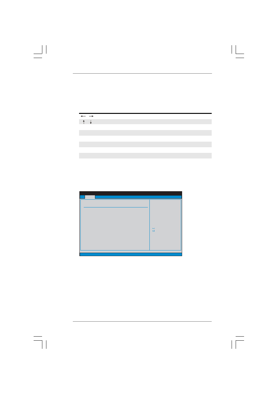
The top of the screen has a menu bar with the following selections:
Main
To set up the system time/date information
Advanced
To set up the advanced BIOS features
H/W Monitor To display current hardware status
Boot
To set up the default system device to locate and load the
Operating System
Security
To set up the security features
Exit
To exit the current screen or the BIOS SETUP UTILITY
Use < > key or < > key to choose among the selections on the menu bar,
and then press <Enter> to get into the sub screen.
2 6
2 6
2 6
2 6
2 6
3.1.2
3.1.2
3.1.2
3.1.2
3.1.2 Navigation Keys
Navigation Keys
Navigation Keys
Navigation Keys
Navigation Keys
Please check the following table for the function description of each navigation
key.
Navigation Key(s)
Function Description
/
Moves cursor left or right to select Screens
/
Moves cursor up or down to select items
+ / -
To change option for the selected items
<Enter>
To bring up the selected screen
<F1>
To display the General Help Screen
<F9>
To load optimal default values for all the settings
<F10>
To save changes and exit the BIOS SETUP UTILITY
<ESC>
To jump to the Exit Screen or exit the current screen
3.2
3.2
3.2
3.2
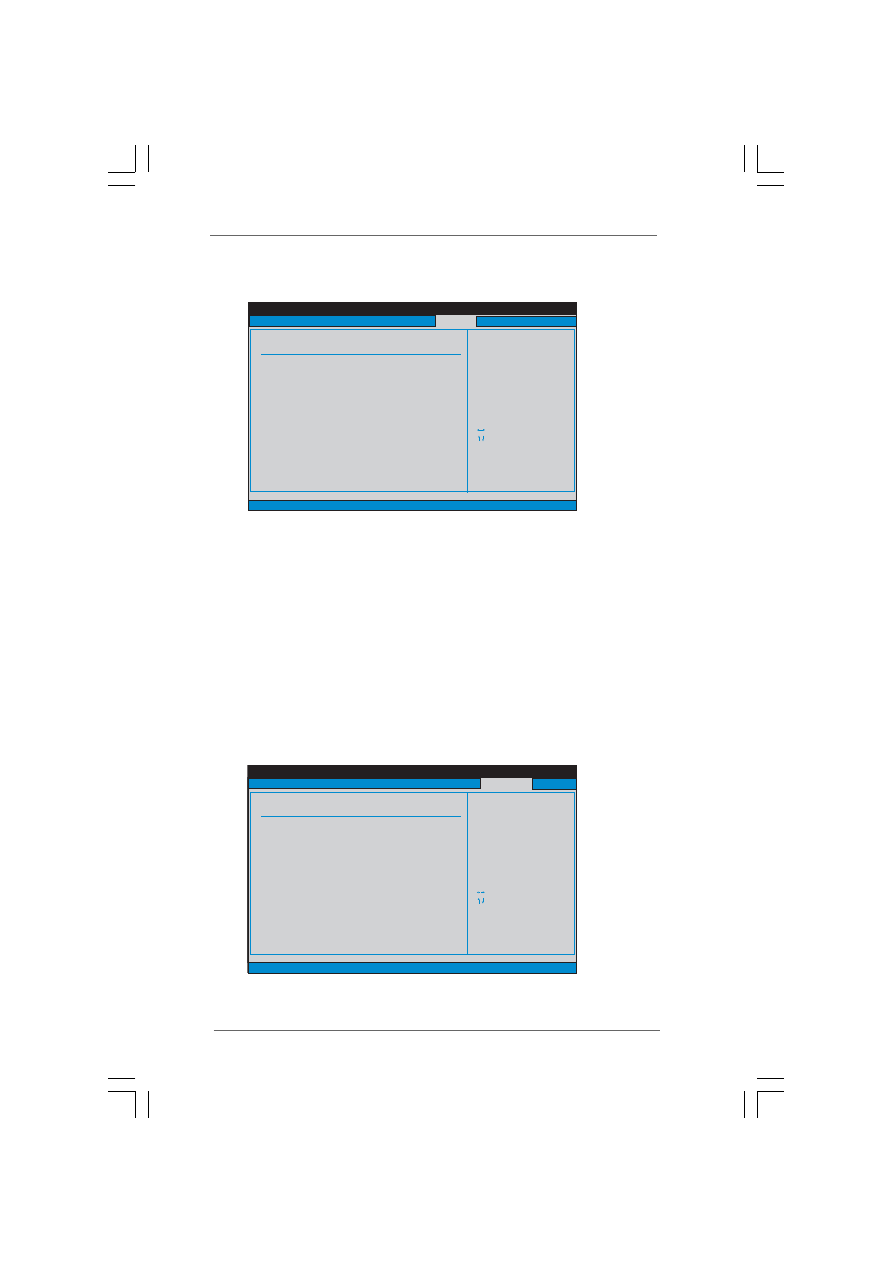
3.2 Main Screen
Main Screen
Main Screen
Main Screen
Main Screen
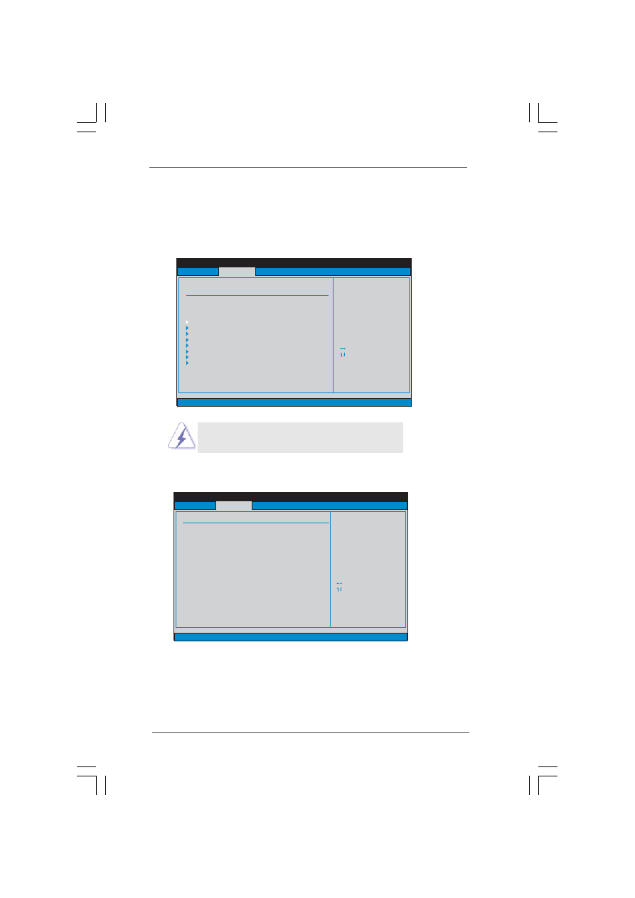
When you enter the BIOS SETUP UTILITY, the Main screen will appear and display
the system overview
System Time [Hour:Minute:Second]
Use this item to specify the system time.
System Date [Day Month/Date/Year]
Use this item to specify the system date.
BIOS SETUP UTILITY
Main
Advanced
H/W Monitor
Boot
Security
Exit
System Overview
System Time
System Date
[
:15:31]
[Thu 05/10/2007]
Use [Enter], [TAB]
or [SHIFT-TAB] to
select a field.
Use [+] or [-] to
configure system Time.
Select Screen
Select Item
+-
Change Field
Tab
Select Field
F1
General Help
F9
Load Defaults
F10
Save and Exit
ESC
Exit
BIOS Version
Processor Type
Processor Speed
Microcode Update
Total Memory
DDR1
DDR2
Cache Size
: P4VM890 BIOS P1.20
: Intel (R) Pentium (R) 4 CPU 2.40GHz
: 2400MHz
:
: 1024KB
: 256MB with 64MB shared memory
: 256MB/166MHz (DDR333)
F33/C
: None
v02.54 (C) Copyright 1985-2003, American Megatrends, Inc.
16
2 7
2 7
2 7
2 7
2 7
BIOS SETUP UTILITY
Main
H/W Monitor
Boot
Security
Exit
Advanced Settings
WARNING : Setting wrong values in below sections
may cause system to malfunction.
Configure CPU
Select Screen
Select Item
Enter Go to Sub Screen
F1
General Help
F9
Load Defaults
F10
Save and Exit
ESC
Exit
v02.54 (C) Copyright 1985-2003, American Megatrends, Inc.
Advanced
CPU Configuration
Chipset Configuration
IDE Configuration
PCIPnP Configuration
Floppy Configuration
SuperIO Configuration
USB Configuration
ACPI Configuration
BIOS SETUP UTILITY
CPU Configuration
CPU Host Frequency
Select how to set the
CPU host frequency.
Select Screen
Select Item
+-
Change Option
F1
General Help
F9
Load Defaults
F10
Save and Exit
ESC
Exit
v02.54 (C) Copyright 1985-2003, American Megatrends, Inc.
Advanced
[Auto]
Spread Spectrum
PCIE/PCI operation mode
Boot Failure Guard
[Auto]
[Async. Mode]
[Enabled]
Select Screen
Select Item
+-
Change Option
F1
General Help
F9
Load Defaults
F10
Save and Exit
ESC
Exit
Actual Frequency (MHz)
[133]
Ratio Status
Ratio Actual Value
Locked
18
Max CPUID Value Limit
CPU Thermal Throttling
Hyper Threading Technology
[Disabled]
[Enabled]
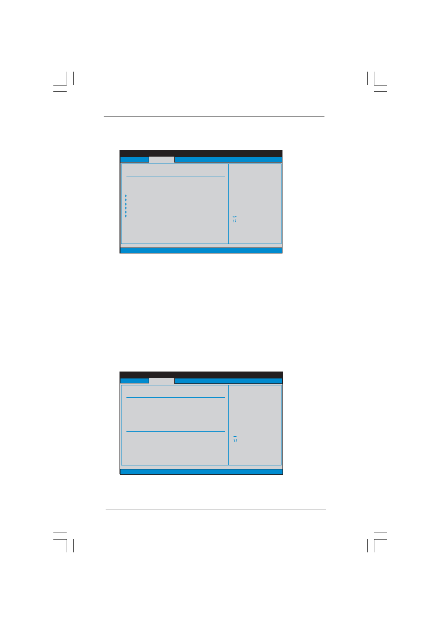
[Enabled]
3.3
3.3
3.3
3.3
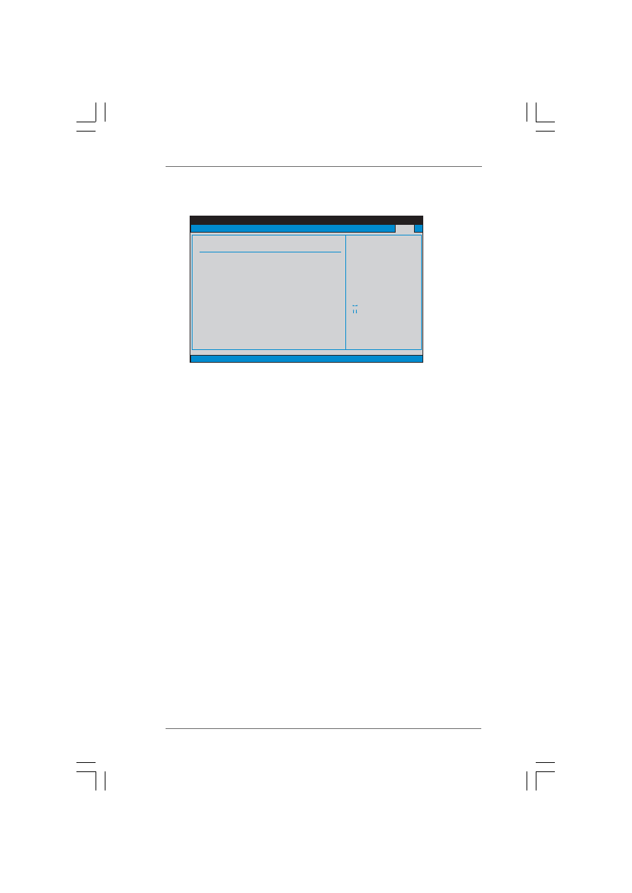
3.3 Advanced Screen
Advanced Screen
Advanced Screen
Advanced Screen
Advanced Screen
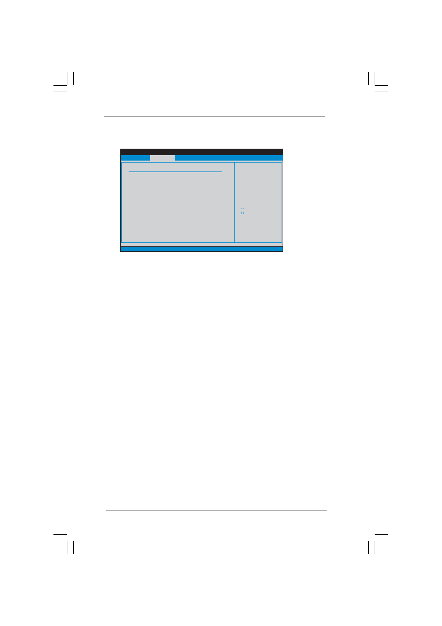
In this section, you may set the configurations for the following items: CPU
Configuration, Chipset Configuration, ACPI Configuration, IDE Configuration, PCIPnP
Configuration, Floppy Configuration, SuperIO Configuration, and USB Configuration.
Setting wrong values in this section may cause
the system to malfunction.
3.3.1
3.3.1
3.3.1
3.3.1
3.3.1 CPU Configuration
CPU Configuration
CPU Configuration
CPU Configuration
CPU Configuration
CPU Host Frequency
While entering setup, BIOS auto detects the present CPU host frequency of
this motherboard. The actual CPU host frequency will show in the following
item.

2 8
2 8
2 8
2 8
2 8
Spread Spectrum
The default value of this option is [Auto].
PCIE/PCI operatin mode
Use this to select PCIE/PCI operation mode. The default value is [Async.
mode]. Configuration options: [Async. mode] and [Sync. mode].
Boot Failure Guard
Enable or disable the feature of Boot Failure Guard.
Ratio Status
This is a read-only item, which displays whether the ratio status of this
motherboard is “Locked” or “Unlocked”. If it shows “Unlocked”, you will
find an item Ratio CMOS Setting appears to allow you changing the ratio
value of this motherboard. If it shows “Locked”, then the item Ratio CMOS
Setting will be hidden. If you use the ratio value to time the CPU frequency,
it will be equal to the core speed of the installed processor.
Ratio Actual Value
This is a read-only item, which displays the ratio actual value of this
motherboard.
Max CPUID Value Limit
For Prescott CPU only, some OSes (ex. NT4.0) cannot handle the function
with disable. This should be enabled in order to boot legacy OSes that
cannot support CPUs with extended CPUID functions.
CPU Thermal Throttling
You may select [Enabled] to enable P4 CPU internal thermal control
mechanism to keep the CPU from overheated.
Hyper Threading Technology
To enable this feature, it requires a computer system with an Intel Pentium
®
4 processor that supports Hyper-Threading technology and an operating
system that includes optimization for this technology, such as Microsoft
®
Windows
®
XP. Set to [Enabled] if using Microsoft
®
Windows
®
XP, or Linux
kernel version 2.4.18 or higher. This option will be hidden if the installed
CPU does not support Hyper-Threading technology.
2 9
2 9
2 9
2 9
2 9
DRAM Frequency
If [Auto] is selected, the motherboard will detect the memory module(s)
inserted and assigns appropriate frequency automatically. You may also
select other value as operating frequency: [166MHz (DDR 333)] and [200MHz
(DDR 400)].
Flexibility Option
The default value of this option is [Disabled]. It will allow better tolerance for
memory compatibility when it is set to [Enabled].
DRAM CAS# Latency
Use this item to adjust the means of memory accessing. Configuration
options: [Auto], [2], [2.5], and [3].
DRAM Bank Interleave
Use this option to select DRAM Bank Interleave. Configuration options:
[Auto], [Disabled], [2-Way], [4-Way], and [8-Way]. The default value is set
to [Auto] to set the timing by dram SPD.
Precharge to Active (Trp)
Use this option to select Precharge to Active (Trp). Configuration options:
[Auto], [2T], [3T], [4T], and [5T]. The default value is set to [Auto] to set the
timing by dram SPD.
Active to Precharge (Tras)
Use this option to select Active to Precharge (Tras). Configuration options:
[Auto], [5T] to [20]. The default value is set to [Auto] to set the timing by dram
SPD.
Active to CMD (Trcd)
Use this option to select Active to CMD (Trcd). Configuration options: [Auto],
[2T], [3T], [4T], and [5T]. The default value is set to [Auto] to set the timing by
dram SPD.
3.3.2
3.3.2
3.3.2
3.3.2
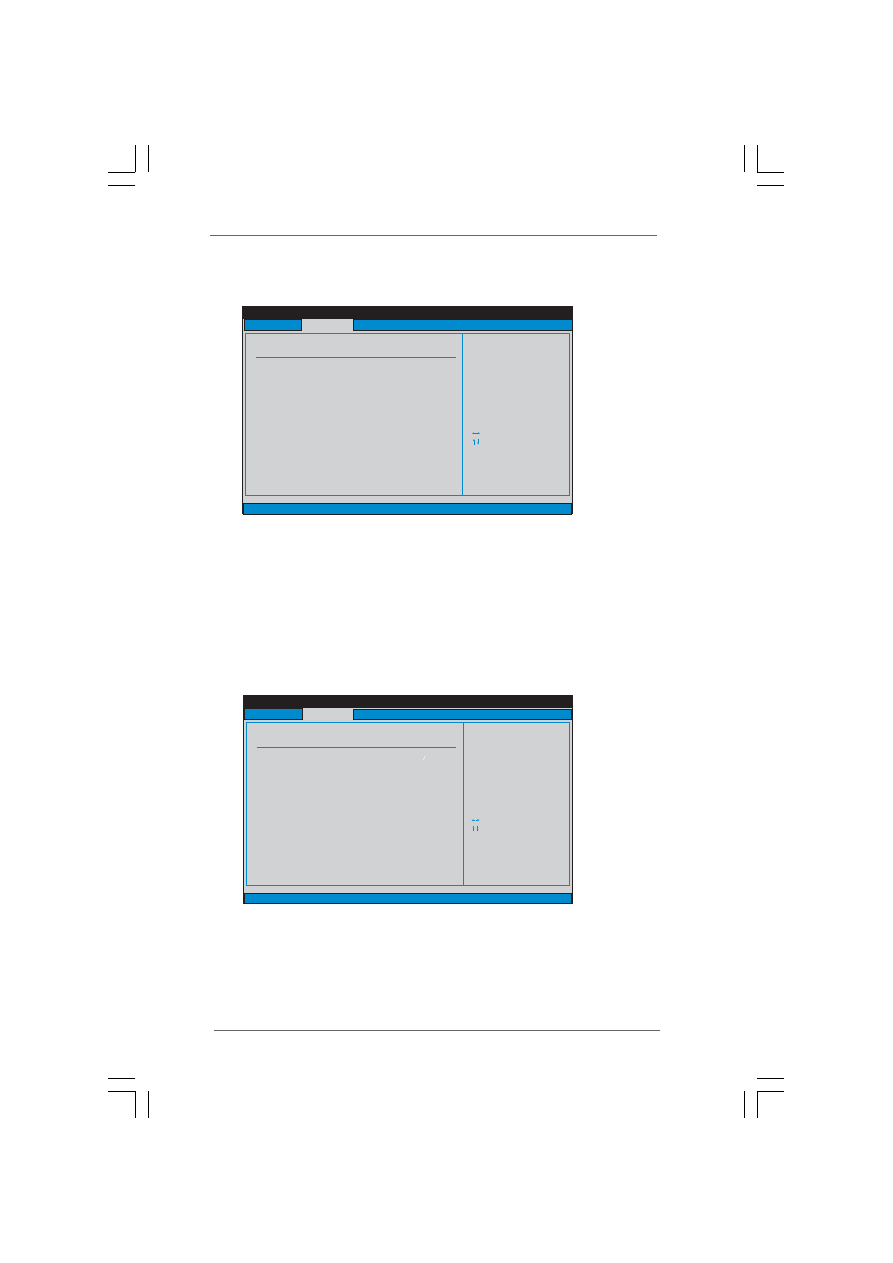
3.3.2 Chipset Configuration
Chipset Configuration
Chipset Configuration
Chipset Configuration
Chipset Configuration
BIOS SETUP UTILITY
v02.54 (C) Copyright 1985-2003, American Megatrends, Inc.
Select Screen
Select Item
+ -
Change Option
F1
General Help
F10
Save and Exit
ESC
Exit
F9
Load Defaults
Memory Clock can be
set by the code using
AUTO, or you can set
one of the standard
values.
Advanced
Chipset Settings
DRAM Frequency
Flexibility Option
DRAM CAS# Latency
DRAM Bank Interleave
Precharge to Active (Trp)
Active to Precharge (Tras)
Active to CMD (Trcd)
REF to ACT/REF to REF (Trfc)
ACT (0) to ACT (1) (Trrd)
Read to Precharge (Trtp)
Write to Read CMD (Twtr)
Write Recovery Time (Twr)
DRAM Command Rate
[Disabled]
[Auto]
[Auto]
[Auto]
[Auto]
[Auto]
[Auto]
[Auto]
[Auto]
[Auto]
[Auto]
[2T Command]
[Auto]

3 0
3 0
3 0
3 0
3 0
REF to ACT / REF to REF (Trfc)
Use this option to select REF to ACT / REF to REF (Trfc). Configuration
options: [Auto], [8T] to [71T]. The default value is set to [Auto] to set the
timing by dram SPD.
ACT(0) to ACT (1) (Trrd)
Use this option to select ACT(0) to ACT (1) (Trrd). Configuration options:
[Auto], [2T], [3T], [4T], and [5T]. The default value is set to [Auto] to set the
timing by dram SPD.
Read to Precharge (Trtp)
Use this option to select Read to Precharge (Trtp). Configuration options:
[Auto], [2T], [3T]. The default value is set to [Auto] to set the timing by dram
SPD.
Write to Read CMD (Twtr)
Use this option to select Write to Read CMD (Twtr). Configuration options:
[Auto], [1T], [2T]. The default value is set to [Auto] to set the timing by dram
SPD.
Write Recovery Time (Twr)
Use this option to select Write Recovery Time (Twr). Configuration options:
[Auto], [2T], [3T], [4T], and [5T]. The default value is set to [Auto] to set the
timing by dram SPD.
DRAM Command Rate
Use this to select among [2T Command] and [1T Command] for DRAM
Command Rate. The default value is [2T Command].
DRAM Voltage
Use this to select DRAM voltage. Configuration options: [Auto], [Normal]
and [High]. The default value is [Auto].
VDDQ Voltage
Use this to select VDDQ voltage. Configuration options: [Auto], [Normal]
and [High]. The default value is [Auto].
Primary Graphics Adapter
This item will switch the PCI Bus scanning order while searching for video
card. It allows you to select the type of Primary VGA in case of multiple
video controllers. The default value of this feature is [PCI]. Configuration
options: [Onboard], [PCI] and [PCI Express].
Share Memory
This allows you to set share memory feature. The default value is [Auto].
Configuration options: [Auto], [32MB] and [64MB].
V-Link Speed
This allows you to set the North Bridge and South Bridge V-Link Speed of
VIA chipset. configuration options: [Normal], [Fast]. The default value is
[Normal].

3 1
3 1
3 1
3 1
3 1
PCI Delay Transaction
Enable PCI Delay Transaction to allow other PCI masters to use the PCI BUS
while the transaction is being carried out on the target device. Disable this
feature when using PCI cards that are not PCI 2.1 compliant.
IDE Drive Strength
This allows you to set the drive strength of the onboard IDE controller.
Configuration options: [Normal], [Low], [Lowest] and [Highest]. The default
value is [Normal].
OnBoard LAN
This allows you to enable or disable the onboard LAN feature.
OnBoard AC’97 Audio
Select [Auto] or [Disabled] for the onboard AC’97 Audio feature.
OnBoard MC’97 Modem
Select [Auto] or [Disabled] for the onboard MC’97 Modem feature.
3 2
3 2
3 2
3 2
3 2
3.3.3
3.3.3
3.3.3
3.3.3
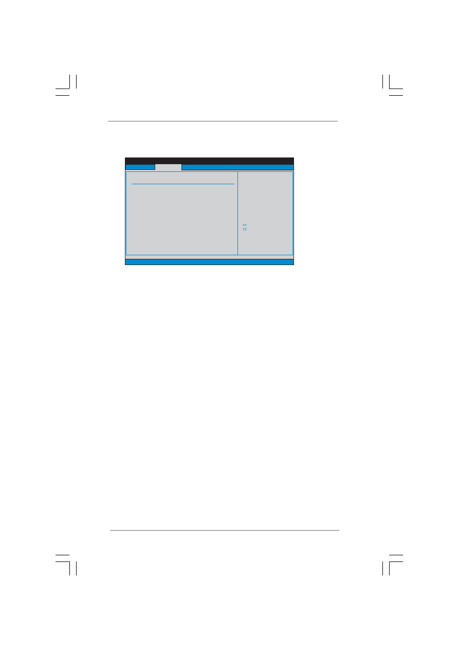
3.3.3 ACPI Configuration
ACPI Configuration
ACPI Configuration
ACPI Configuration
ACPI Configuration
Suspend to RAM
This field allows you to select whether to auto-detect or disable the Sus
pend-to-RAM feature. Select [Auto] will enable this feature if the system
supports it.
Restore on AC/Power Loss
This allows you to set the power state after an unexpected AC/
Power loss. If [Power Off] is selected, the AC/Power remains off
when the power recovers. If [Power On] is selected, the AC/Power
resumes and the system starts to boot up when the power recovers.
Ring-In Power On
Use this item to enable or disable Ring-In signals to turn on the system from
the power-soft-off mode.
PCI Devices Power On
Use this item to enable or disable PCI devices to turn on the system from the
power-soft-off mode.
PS/2 Keyboard Power On
Use this item to enable or disable PS/2 keyboard to turn on the system from
the power-soft-off mode.
RTC Alarm Power On
Use this item to enable or disable RTC (Real Time Clock) to power on the
system.
BIOS SETUP UTILITY
ACPI Configuration
Select auto-detect or
disable the STR
feature.
Select Screen
Select Item
+-
Change Option
F1
General Help
F9
Load Defaults
F10
Save and Exit
ESC
Exit
v02.54 (C) Copyright 1985-2003, American Megatrends, Inc.
Advanced
Suspend To RAM
Restore on AC / Power Loss
Ring-In Power On
PCI Devices Power On
PS / 2 Keyboard Power On
RTC Alarm Power On
[Disabled]
[Power Off]
[Disabled]
[Disabled]
[Disabled]
[Disabled]
3 3
3 3
3 3
3 3
3 3
3.3.4
3.3.4
3.3.4
3.3.4
3.3.4 IDE Configuration
IDE Configuration
IDE Configuration
IDE Configuration
IDE Configuration
OnBoard IDE Controller
Use this item to enable or disable onboard IDE controller. Configuration
options: [Enabled] and [Disabled].
SATA Operation Mode
Use this item to adjust SATA Operation Mode. Please set this item to [RAID]
if you want to operate RAID functions with Windows
®
2000 / XP. Otherwise,
please set this item to [non-RAID].
IDE Device Configuration
You may set the IDE configuration for the device that you specify. We will
use the “Primary IDE Master” as the example in the following instruction,
which can be applied to the configurations of “Primary IDE Slave”, “Sec-
ondary IDE Master”, and “Secondary IDE Slave” as well.
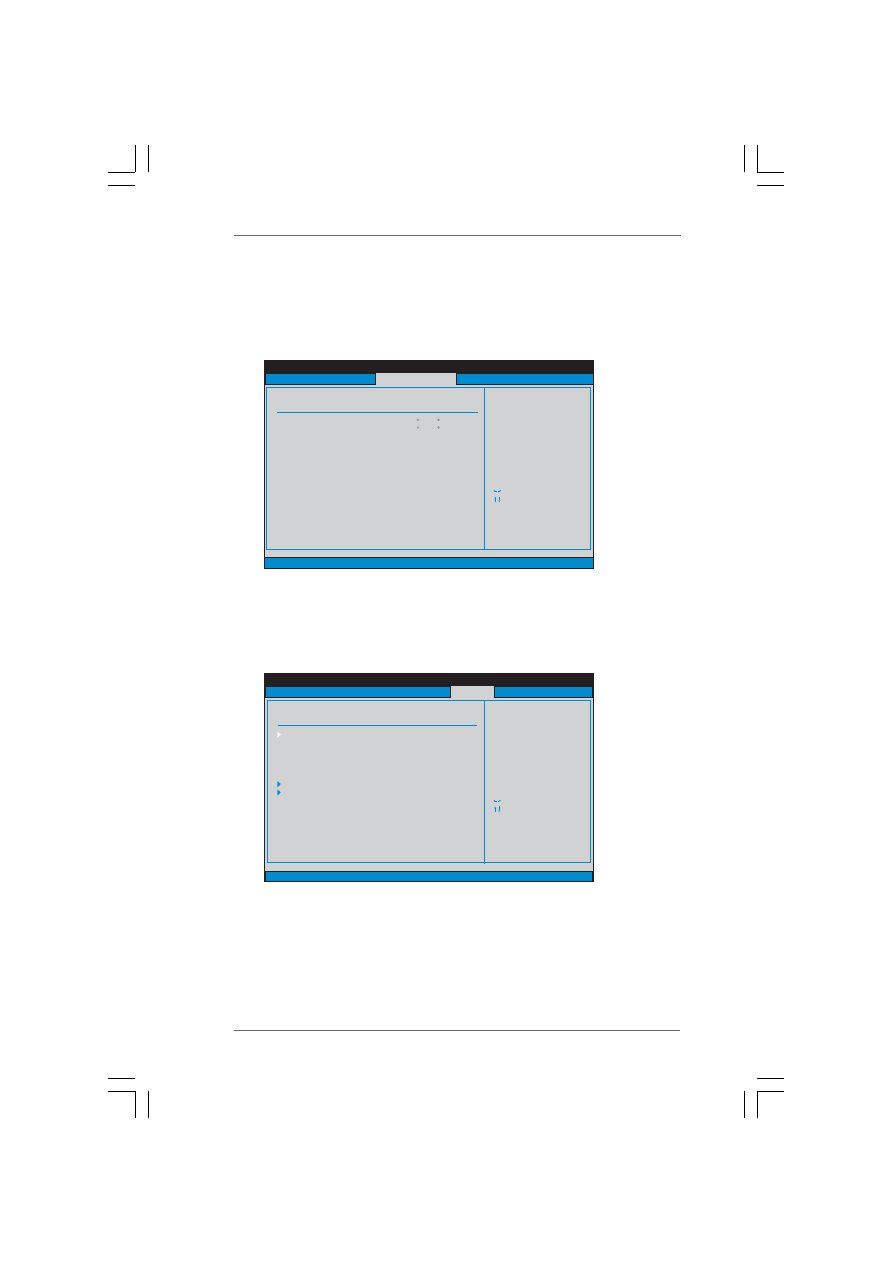
BIOS SETUP UTILITY
IDE Configuration
v02.54 (C) Copyright 1985-2003, American Megatrends, Inc.
Advanced
OnBoard IDE Controller
Primary IDE Master
Primary IDE Slave
Secondary IDE Master
Secondary IDE Slave
SATA 1
SATA 2
[Enabled]
[Hard Disk]
[Not Detected]
[Not Detected]
[Not Detected]
[Not Detected]
[Not Detected]
Select Screen
Select Item
+-
Change Option
F1
General Help
F9
Load Defaults
F10
Save and Exit
ESC
Exit
Select Screen
Select Item
+-
Change Option
F1
General Help
F9
Load Defaults
F10
Save and Exit
ESC
Exit
To enable or disable
the onboard IDE
controller.
SATA Operation Mode
[RAID]
BIOS SETUP UTILITY
Primary IDE Master
Select the type
of device connected
to the system.
Select Screen
Select Item
+-
Change Option
F1
General Help
F9
Load Defaults
F10
Save and Exit
ESC
Exit
v02.54 (C) Copyright 1985-2003, American Megatrends, Inc.
Advanced
Type
LBA/Large Mode
Block (Multi-Sector Transfer)
PIO Mode
DMA Mode
S . M . A . R . T .
32Bit Data Transfer
[Auto]
[Auto]
[Auto]
[Auto]
[Auto]
[Disabled]
[Disabled]
Device
Vendor
Size
LBA Mode
Block Mode
PIO Mode
Async DMA
Ultra DMA
S.M.A.R.T.
:Hard Disk
:ST340014A
:40.0 GB
:Supported
:16Sectors
:4
:MultiWord DMA-2
:Ultra DMA-5
:Supported

3 4
3 4
3 4
3 4
3 4
TYPE
Use this item to configure the type of the IDE device that you specify.
Configuration options: [Not Installed], [Auto], [CD/DVD], and [ARMD].
[Not Installed]: Select [Not Installed] to disable the use of IDE device.
[Auto]: Select [Auto] to automatically detect the hard disk drive.
After selecting the hard disk information into BIOS, use a disk
utility, such as FDISK, to partition and format the new IDE hard
disk drives. This is necessary so that you can write or read
data from the hard disk. Make sure to set the partition of the
Primary IDE hard disk drives to active.
[CD/DVD]: This is used for IDE CD/DVD drives.
[ARMD]: This is used for IDE ARMD (ATAPI Removable Media Device),
such as MO.
LBA/Large Mode
Use this item to select the LBA/Large mode for a hard disk > 512 MB under
DOS and Windows; for Netware and UNIX user, select [Disabled] to
disable the LBA/Large mode.
Block (Multi-Sector Transfer)
The default value of this item is [Auto]. If this feature is enabled, it will
enhance hard disk performance by reading or writing more data during
each transfer.
PIO Mode
Use this item to set the PIO mode to enhance hard disk performance by
optimizing the hard disk timing.
DMA Mode
DMA capability allows the improved transfer-speed and data-integrity for
compatible IDE devices.
S.M.A.R.T.
Use this item to enable or disable the S.M.A.R.T. (Self-Monitoring, Analysis,
and Reporting Technology) feature. Configuration options: [Disabled], [Auto],
[Enabled].
32-Bit Data Transfer
Use this item to enable 32-bit access to maximize the IDE hard disk data
transfer rate.
3 5
3 5
3 5
3 5
3 5
3.3.5
3.3.5
3.3.5
3.3.5
3.3.5 PCIPnP Configuration
PCIPnP Configuration
PCIPnP Configuration
PCIPnP Configuration
PCIPnP Configuration
PCI Latency Timer
The default value is 32. It is recommended to keep the default value unless
the installed PCI expansion cards’ specifications require other settings.
PCI IDE BusMaster
Use this item to enable or disable the PCI IDE BusMaster feature.
3.3.6
3.3.6
3.3.6
3.3.6
3.3.6 Floppy Configuration
Floppy Configuration
Floppy Configuration
Floppy Configuration
Floppy Configuration
In this section, you may configure the type of your floppy drive.
BIOS SETUP UTILITY
Advanced PCI / PnP Settings
Value in units of PCI
clocks for PCI device
latency timer
register.
Select Screen
Select Item
+-
Change Option
F1
General Help
F9
Load Defaults
F10
Save and Exit
ESC
Exit
v02.54 (C) Copyright 1985-2003, American Megatrends, Inc.
PCI Latency Timer
PCI IDE BusMaster
[32]
[Enabled]
Advanced
BIOS SETUP UTILITY
Floppy Configuration
Select the type of
floppy drive
connected to the
system.
Select Screen
Select Item
+-
Change Option
F1
General Help
F9
Load Defaults
F10
Save and Exit
ESC
Exit
v02.54 (C) Copyright 1985-2003, American Megatrends, Inc.
Advanced
Floppy A
[1.44 MB 3 "]
1
2
Floppy B
[Disabled]

3 6
3 6
3 6
3 6
3 6
3.3.7
3.3.7
3.3.7
3.3.7
3.3.7 Super IO Configuration
Super IO Configuration
Super IO Configuration
Super IO Configuration
Super IO Configuration
OnBoard Floppy Controller
Use this item to enable or disable floppy drive controller.
Serial Port Address
Use this item to set the address for the onboard serial port or disable it.
Configuration options: [Disabled], [3F8 / IRQ4], [2F8 / IRQ3], [3E8 / IRQ4],
[2E8 / IRQ3].
Infrared Port Address
Use this item to set the address for the onboard infrared port or disable it.
Configuration options: [Disabled], [2F8 / IRQ3], and [2E8 / IRQ3].
Parallel Port Address
Use this item to set the address for the onboard parallel port or disable it.
Configuration options: [Disabled], [378], and [278].
Parallel Port Mode
Use this item to set the operation mode of the parallel port. The default
value is [ECP+EPP]. If this option is set to [ECP+EPP], it will show the EPP
version in the following item, “EPP Version”. Configuration options:
[Normal], [Bi-Directional], and [ECP+EPP].
EPP Version
Use this item to set the EPP version. Configuration options: [1.9]
and [1.7].
ECP Mode DMA Channel
Use this item to set the ECP mode DMA channel. Configuration
options: [DMA0], [DMA1], and [DMA3].
Parallel Port IRQ
Use this item to set the IRQ for the parallel port. Configuration options:
[IRQ5] and [IRQ7].
BIOS SETUP UTILITY
Configure Super IO Chipset
Allow BIOS to Enable
or Disable Floppy
Controller.
Select Screen
Select Item
+-
Change Option
F1
General Help
F9
Load Defaults
F10
Save and Exit
ESC
Exit
v02.54 (C) Copyright 1985-2003, American Megatrends, Inc.
Advanced
OnBoard Floppy Controller
Serial Port Address
Infrared Port Address
Parallel Port Address
Parallel Port Mode
EPP Version
ECP Mode DMA Channel
Parallel Port IRQ
[Enabled]
[3F8 / IRQ4]
[Disabled]
[378]
[ECP + EPP]
[1.9]
[DMA3]
[IRQ7]
3 7
3 7
3 7
3 7
3 7
3.3.8
3.3.8
3.3.8
3.3.8
3.3.8 USB Configuration
USB Configuration
USB Configuration
USB Configuration
USB Configuration
USB Controller
Use this item to enable or disable the use of USB controller.
USB 2.0 Support
Use this item to enable or disable the USB 2.0 support.
Legacy USB Support
Use this item to enable or disable the support to emulate legacy I/O
devices such as mouse, keyboard,... etc. Or you may select [Auto] so
that the system will start to auto-detect; if there is no USB device
connected, “Auto” option will disable the legacy USB support.
BIOS SETUP UTILITY
USB Configuration
To enable or disable
the onboard USB
controllers.
Select Screen
Select Item
+-
Change Option
F1
General Help
F9
Load Defaults
F10
Save and Exit
ESC
Exit
v02.54 (C) Copyright 1985-2003, American Megatrends, Inc.
Advanced
USB Controller
USB 2.0 Support
Legacy USB Support
[Enabled]
[Enabled]
[Disabled]
3 8
3 8
3 8
3 8
3 8
3.4
3.4
3.4
3.4
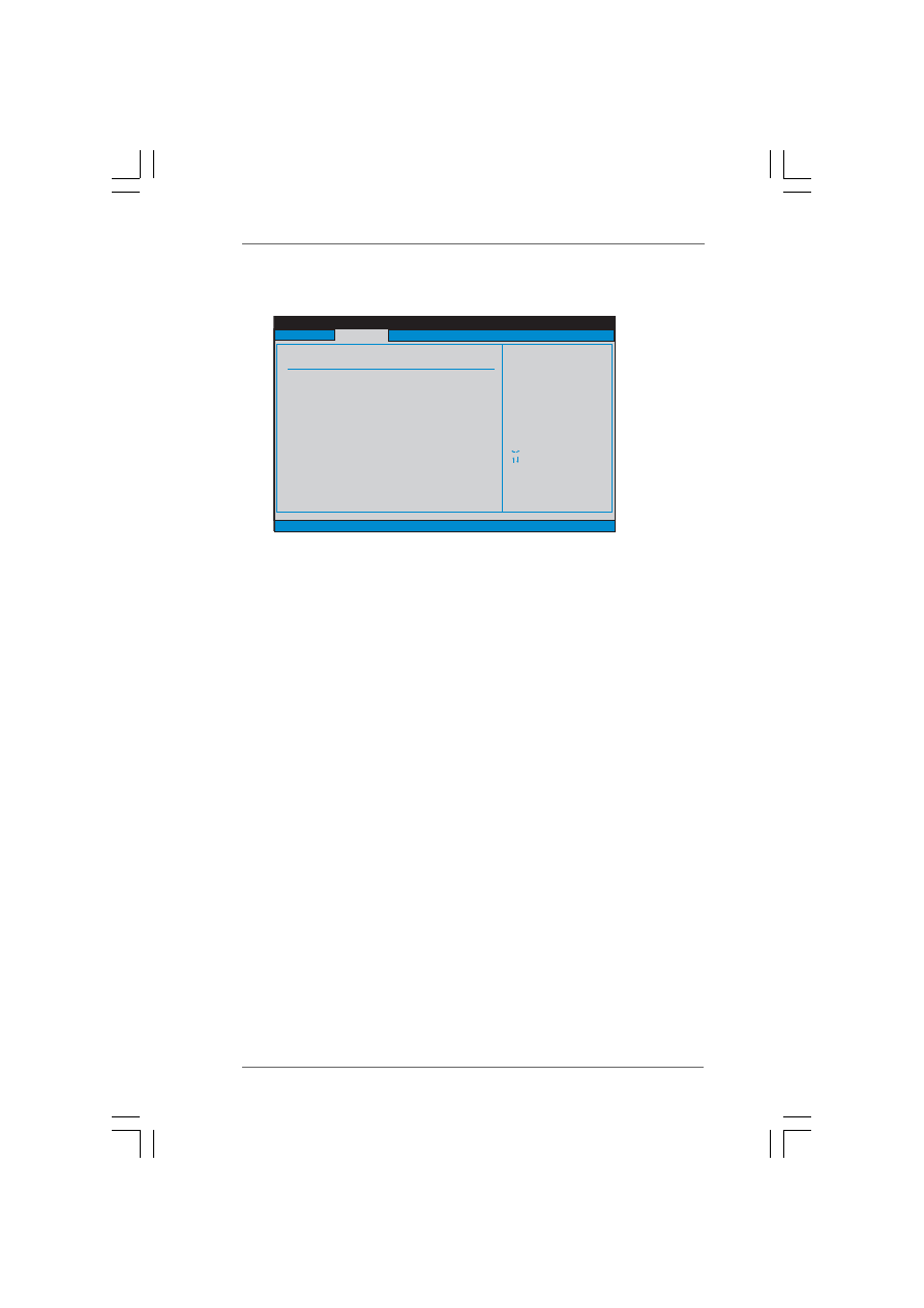
3.4 Hardware Health Event Monitoring Screen
Hardware Health Event Monitoring Screen
Hardware Health Event Monitoring Screen
Hardware Health Event Monitoring Screen
Hardware Health Event Monitoring Screen
In this section, it allows you to monitor the status of the hardware on your system,
including the parameters of the CPU temperature, motherboard temperature, CPU fan
speed, chassis fan speed, and the critical voltage.
3.5
3.5
3.5
3.5
3.5 Boot Screen
Boot Screen
Boot Screen
Boot Screen
Boot Screen
In this section, it will display the available devices on your system for you to config-
ure the boot settings and the boot priority.
BIOS SETUP UTILITY
Hardware Health Event Monitoring
Select Screen
Select Item
F1
General Help
F9
Load Defaults
F10
Save and Exit
ESC
Exit
v02.54 (C) Copyright 1985-2003, American Megatrends, Inc.
CPU Temperature
M / B Temperature
CPU Fan Speed
Chassis Fan Speed
Vcore
+ 3.30V
+ 5.00V
+ 12.00V
: 37 C / 98 F
: 2463 RPM
: N / A
: 1.629V
: 3.306V
: 5.067V
: 11.890V
: 31 C / 87 F
Main
Advanced
Boot
Security
Exit
H/W Monitor
BIOS SETUP UTILITY
Main
Advanced
H/W Monitor
Security
Exit
Boot Settings
Configure Settings
during System Boot.
Select Screen
Select Item
Enter Go to Sub Screen
F1
General Help
F9
Load Defaults
F10
Save and Exit
ESC
Exit
v02.54 (C) Copyright 1985-2003, American Megatrends, Inc.
Boot
Boot Settings Configuration
1st Boot Device
2nd Boot Device
3rd Boot Device
4th Boot Device
Hard Disk Drives
Removable Drives
[1st Floppy Device]
[HDD: PM - MAXTOR 6L08]
[CD / DVD]
[USB]
3 9
3 9
3 9
3 9
3 9
3.5.1
3.5.1
3.5.1
3.5.1
3.5.1 Boot Settings Configuration
Boot Settings Configuration
Boot Settings Configuration
Boot Settings Configuration
Boot Settings Configuration
Boot From Network
Use this item to enable or disable the Boot From Network feature.
VIA SATA Raid Utility
Use this to enable or disable VIA
®
VT8237R Plus SATA Raid BIOS Utility
during POST.
Boot Up Num-Lock
If this item is set to [On], it will automatically activate the Numeric Lock
function after boot-up.
3.6
3.6
3.6
3.6
3.6 Security Screen
Security Screen
Security Screen
Security Screen
Security Screen
In this section, you may set or change the supervisor/user password for the system.
For the user password, you may also clear it.
BIOS SETUP UTILITY
Boot Settings Configuration
To enable or disable the
boot from network feature.
Select Screen
Select Item
+ -
Change Option
F1
General Help
F9
Load Defaults
F10
Save and Exit
ESC
Exit
v02.54 (C) Copyright 1985-2003, American Megatrends, Inc.
Boot
Boot From Network
VIA SATA Raid Utility
Bootup Num-Lock
[Disabled]
[Enabled]
[On]
BIOS SETUP UTILITY
Main
Advanced
H/W Monitor
Boot
Exit
Install or Change the
password.
Select Screen
Select Item
Enter Change
F1
General Help
F10
Save and Exit
ESC
Exit
F9
Load Defaults
v02.54 (C) Copyright 1985-2003, American Megatrends, Inc.
Security
Change Supervisor Password
Change User Password
Security Settings
Supervisor Password
: Not Installed
User Password
: Not Installed
4 0
4 0
4 0
4 0
4 0
3.7
3.7
3.7
3.7
3.7 Exit Screen
Exit Screen
Exit Screen
Exit Screen
Exit Screen
Save Changes and Exit
When you select this option, it will pop-out the following message, “Save
configuration changes and exit setup?” Select [OK] to save the changes
and exit the BIOS SETUP UTILITY.
Discard Changes and Exit
When you select this option, it will pop-out the following message, “Dis-
card changes and exit setup?” Select [OK] to exit the BIOS SETUP UTILITY
without saving any changes.
Discard Changes
When you select this option, it will pop-out the following message, “Dis-
card changes?” Select [OK] to discard all changes.
Load Optimal Defaults
When you select this option, it will pop-out the following message, “Load
optimal defaults?” Select [OK] to load the default values for all the setup
configurations.
BIOS SETUP UTILITY
Main
Advanced
H/W Monitro
Boot
Security
Exit system setup
after saving the
changes.
F10 key can be used
for this operation.
Select Screen
Select Item
Enter Go to Sub Screen
F1
General Help
F10
Save and Exit
ESC
Exit
F9
Load Defaults
v02.54 (C) Copyright 1985-2003, American Megatrends, Inc.
Exit
Save Changes and Exit
Discard Changes and Exit
Discard Changes
Load Optimal Defaults
Exit Options

4 1
4 1
4 1
4 1
4 1
4.
4.
4.
4.
4. Software Suppor
Software Suppor
Software Suppor
Software Suppor
Software Supporttttt
4.1 Install Operating System
4.1 Install Operating System
4.1 Install Operating System
4.1 Install Operating System
4.1 Install Operating System
This motherboard supports various Microsoft
®
Windows
®
operating systems: 2000 /
XP. Because motherboard settings and hardware options vary, use the setup pro-
cedures in this chapter for general reference only. Refer to your OS documentation
for more information.
4.2 Support CD Information
4.2 Support CD Information
4.2 Support CD Information
4.2 Support CD Information
4.2 Support CD Information
The Support CD that came with the motherboard contains necessary drivers and
useful utilities that enhance the motherboard features.
4.2.1 Running The Support CD
4.2.1 Running The Support CD
4.2.1 Running The Support CD
4.2.1 Running The Support CD
4.2.1 Running The Support CD
To begin using the support CD, insert the CD into your CD-ROM drive. The CD
automatically displays the Main Menu if “AUTORUN” is enabled in your computer.
If the Main Menu did not appear automatically, locate and double click on the file
“ASSETUP.EXE” from the BIN folder in the Support CD to display the menus.
4.2.2 Drivers Menu
4.2.2 Drivers Menu
4.2.2 Drivers Menu
4.2.2 Drivers Menu
4.2.2 Drivers Menu
The Drivers Menu shows the available devices drivers. Please install the
necessary drivers to activate the devices.
4.2.3 Utilities Menu
4.2.3 Utilities Menu
4.2.3 Utilities Menu
4.2.3 Utilities Menu
4.2.3 Utilities Menu
The Utilities Menu shows the applications software that the motherboard supports.
Click on a specific item then follow the installation wizard to install it.
4.2.4
4.2.4
4.2.4
4.2.4
4.2.4 Contact Information
Contact Information
Contact Information
Contact Information
Contact Information
If you need to contact ASRock or want to know more about ASRock, welcome
to visit ASRock’s website at http://www.asrock.com; or you may contact your
dealer for further information.
Wyszukiwarka
Podobne podstrony:
PM [R2] Sylabus ENG
KODY SERWISOWE NOKIA by asrock11, Moje Prace
wos zp r2 prawo test b odp
MP1580 r2 9w
Rozdział 9, ZiIP, ZiIP, R2, SI, Przygotowanie Produkcji, pp
IM R2 S3
wos zp r2 prawo test a odp
Egzamin 70412 Konfigurowanie zaawansowanych uslug Windows Server 2012 R2 Dillard Kurt
Installing WSUS for Configuration Manager 2012 R2
ento 2kolo R2, Studia, II rok, II rok, IV semestr, Entomologia
czynności obsługi technicznej honda civic gen 5 by asrock11
R2 Międzynarodowe Stosunki Polityczne
WOS wos zp r2 prawo test b odp
Teoria, R2-2
ROZDZIAŁ VI w, ZiIP, ZiIP, R2, SI, Przygotowanie Produkcji, pp
ASRock ConRoe865PE id 70853 Nieznany (2)
SHSBC253 R2 10 AND R2 12
CANBus CH?libration r2
więcej podobnych podstron