1 - 8
CCNP: Optimizing Converged Networks v5.0 - Lab 4-9
Copyright
© 2007, Cisco Systems, Inc
Lab 4.9 QoS Pre-classify
Learning Objectives
• Configure a GRE tunnel
• Configure
QoS
pre-classify
• Verify QoS pre-classify operation
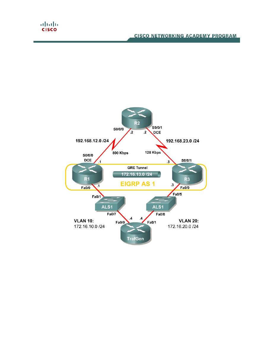
Topology Diagram
Scenario
Weighted fair queuing (WFQ) allows routers to determine the ordering of
packets for transmission on the basis of the flow or conversation into which a
packet falls. A flow is defined by the source and destination addresses and port
numbers, the transport protocol, and the IP Precedence value.
Both Generic Routing Encapsulation (GRE) and IPsec tunnels copy a packet’s
markable type of service/differentiated services (ToS/DiffServ) byte from the
inner header to the outer header during encapsulation. Flow-based tools all
along the tunnel’s path will be able to view the IP Precedence or differentiated

services code point (DSCP) marking. However, WFQ manages the allocation of
network bandwidth by classifying traffic into prioritized flows, and dividing the
network bandwidth fairly between those flows. Along the majority of the tunnel
path, the only information able to be used to classify traffic will be the
ToS/DiffServ byte.
However, at the tunnel endpoints you can make more intelligent decisions
about the prioritization of packets because you have access to the inner
packets before you encapsulate them with another IP header.
This scenario will guide you through implementing the QoS pre-classify feature
to ensure that flow-based tools can make more intelligent decisions in
provisioning bandwidth for tunneled flows.
Preparation
This lab uses the Basic Pagent Configuration for TrafGen and the switch to
generate and facilitate lab traffic in a stream from TrafGen to R1 to R2. Prior to
beginning this lab, configure TrafGen (R4) and the switch according to the
Basic Pagent Configuration in Lab 3.1: Preparing for QoS. You can accomplish
this easily on R4 by loading the basic-ios.cfg file from flash memory into the
NVRAM, and reloading.
TrafGen# copy flash:basic-ios.cfg startup-config
Destination filename [startup-config]?
[OK]
2875 bytes copied in 1.456 secs (1975 bytes/sec)
TrafGen# reload
Proceed with reload? [confirm]
On the switch, load the basic.cfg file into NVRAM and reload the device.
Switch# copy flash:basic.cfg startup-config
Destination filename [startup-config]?
[OK]
2875 bytes copied in 1.456 secs (1975 bytes/sec)
TrafGen# reload
Proceed with reload? [confirm]
On TrafGen, instruct TGN to load the basic-tgn.cfg file and to start generating
traffic.
TrafGen# tgn load-config basic-tgn.cfg
TrafGen# tgn start
In addition, add the Fast Ethernet 0/5 interface on the switch to VLAN 20 since
R3 will be the exit point from the network topology in this lab.
Switch# configure terminal
Switch(config)# interface fastethernet 0/5
Switch(config-if)# switchport access vlan 20
Switch(config-if)# switchport mode access
2 - 8
CCNP: Optimizing Converged Networks v5.0 - Lab 4-9
Copyright
© 2007, Cisco Systems, Inc

Step 1: Configure the Physical Interfaces
Configure all of the physical interfaces shown in the diagram. Set the clock rate
on the serial link between R1 and R2 to 800000, the clock rate of the serial link
between R2 and R3 to be 128000, and use the no shutdown command on all
interfaces. Set the informational bandwidth parameter on the serial interfaces.
R1(config)# interface fastethernet 0/0
R1(config-if)# ip address 172.16.10.1 255.255.255.0
R1(config-if)# no shutdown
R1(config-if)# interface serial 0/0/0
R1(config-if)# bandwidth 800
R1(config-if)# ip address 192.168.12.1 255.255.255.0
R1(config-if)# clock rate 800000
R1(config-if)# no shutdown
R2(config)# interface serial 0/0/0
R2(config-if)# bandwidth 800
R2(config-if)# ip address 192.168.12.2 255.255.255.0
R2(config-if)# no shutdown
R2(config-if)# interface serial 0/0/1
R2(config-if)# bandwidth 128
R2(config-if)# ip address 192.168.23.2 255.255.255.0
R2(config-if)# clock rate 128000
R2(config-if)# no shutdown
R3(config)# interface fastethernet 0/0
R3(config-if)# ip address 172.16.20.3 255.255.255.0
R3(config-if)# no shutdown
R3(config-if)# interface serial 0/0/1
R3(config-if)# bandwidth 128
R3(config-if)# ip address 192.168.23.3 255.255.255.0
R3(config-if)# no shutdown
Issue the show interfaces serial 0/0/0 | include Queueing command on R1 to
verify that the queuing strategy is WFQ.
R1# show interface serial0/0/0 | include Queueing
Queueing strategy: weighted fair
If you see “fifo” as the queuing type, use the interface-level fair-queue
command on the serial interface to change the queuing strategy to WFQ.
Step 2: Configure Static Routing
Configure R1 and R3 with default routes towards R2.
R1(config)# ip route 0.0.0.0 0.0.0.0 192.168.12.2
R3(config)# ip route 0.0.0.0 0.0.0.0 192.168.23.2
To which destination networks will R2 be able to forward IP traffic?
3 - 8
CCNP: Optimizing Converged Networks v5.0 - Lab 4-9
Copyright
© 2007, Cisco Systems, Inc

Does R2 have any knowledge of how to route to the 172.16.0.0/16 major
network?
Step 3: Configure the GRE Tunnel
Your company currently maintains a GRE tunnel through the ISP router R2
terminating at R1 and R3. Create the tunnel interfaces on both R1 and R3 and
use the addresses in the 192.168.0.0/16 address range as the endpoints of the
tunnel. Use IP addresses in the 172.16.23.0/24 subnet as the addressing for
the tunnel interfaces themselves. R2 does not need to have routing information
for the network addresses you use in your private network (172.16.0.0/16).
Create a GRE tunnel interface, by issuing the interface tunnel number
command to enter interface configuration mode for the tunnel interface. The
tunnel interface number is only locally significant; however, for simplicity, use
tunnel interface number 0 on both R1 and R3. Next, configure addressing for
the tunnel interface itself with the ip address address mask command, just like
you would do on any other interface. Finally, assign a source and destination
address for the tunnel with the tunnel source address and tunnel destination
address commands, respectively. The tunnel source can alternatively be
specified by interface.
Tunneled traffic will be first sent to the other end of the GRE tunnel before being
forwarded to its destination. Tunneling accomplishes this function by
encapsulating packets with an outer IP header with the source and destination
addresses supplied with the two previous commands. You do not need to
configure a tunnel mode because the default tunnel mode is GRE. For more
information on configuring GRE tunnels, reference the ISCW Lab 3.2:
Configuring GRE Tunnels.
R1(config)# interface tunnel 0
R1(config-if)# tunnel source serial 0/0/0
R1(config-if)# tunnel destination 192.168.23.3
R1(config-if)# ip address 172.16.13.1 255.255.255.0
R3(config)# interface tunnel 0
R3(config-if)# tunnel source serial 0/0/1
R3(config-if)# tunnel destination 192.168.12.1
R3(config-if)# ip address 172.16.13.3 255.255.255.0
Verify that you can ping across the tunnel to the other side. If you can do this,
you have successfully set up the tunnel.
R1# ping 172.16.13.3
4 - 8
CCNP: Optimizing Converged Networks v5.0 - Lab 4-9
Copyright
© 2007, Cisco Systems, Inc

Type escape sequence to abort.
Sending 5, 100-byte ICMP Echos to 172.16.13.3, timeout is 2 seconds:
!!!!!
Success rate is 100 percent (5/5), round-trip min/avg/max = 20/28/44 ms
R3# ping 172.16.13.1
Type escape sequence to abort.
Sending 5, 100-byte ICMP Echos to 172.16.13.1, timeout is 2 seconds:
!!!!!
Success rate is 100 percent (5/5), round-trip min/avg/max = 12/24/36 ms
Step 4: Configure Routing
Configure routing between R1 and R3 using Enhanced Interior Gateway
Routing Protocol (EIGRP). Include the entire 172.16.0.0/16 major network in AS
1 and disable automatic summarization.
R1(config)# router eigrp 1
R1(config-router)# no auto-summary
R1(config-router)# network 172.16.0.0
R3(config)# router eigrp 1
R3(config-router)# no auto-summary
R3(config-router)# network 172.16.0.0
Verify that the number of packets counted is increasing on the outbound
interface of R3 using the show interfaces fastethernet 0/1 command. Issue
the command twice to make sure the number of packets output has changed. If
the number is not increasing, troubleshoot Layer 1, 2, and 3 connectivity and
the EIGRP topology.
If a tunnel’s queuing strategy is first-in, first-out (FIFO), you may experience
extreme delays in sending EIGRP packets over your tunnel. Remember that all
of the traffic generated by Pagent is attempting to traverse the link as well and
may cause delays in sending the EIGRP hellos.
Step 5: Enable the QoS Pre-classify Feature
On R1, issue the show queue interface command to view the open
conversations exiting the Serial 0/0/0 interface.
R1 show queue serial 0/0/0
Input queue: 0/75/0/0 (size/max/drops/flushes); Total output drops: 5798913
Queueing strategy: weighted fair
Output queue: 64/1000/64/5798913 (size/max total/threshold/drops)
Conversations 1/10/256 (active/max active/max total)
Reserved Conversations 0/0 (allocated/max allocated)
Available Bandwidth 1158 kilobits/sec
(depth/weight/total drops/no-buffer drops/interleaves) 64/32384/2643514/0/0
Conversation 38, linktype: ip, length: 991
source: 192.168.12.1, destination: 192.168.23.3, id: 0x45C8, ttl: 255, prot:
47
5 - 8
CCNP: Optimizing Converged Networks v5.0 - Lab 4-9
Copyright
© 2007, Cisco Systems, Inc

Notice there is only one conversation. The protocol number at the end is 47,
which is GRE—the default tunnel encapsulation.
Why is there only one conversation listed, despite multiple traffic flows coming
out of TrafGen?
Does GRE copy the inner IP header’s ToS/DiffServ byte to the encapsulating IP
header?
On the basis of your answer to the previous question and given the current
configuration of the network, what is the maximum number of tunneled GRE
conversations that could be seen in the output of the show queue serial 0/0/0
command?
QoS pre-classify allows traffic to be classified by the physical interface’s flow-
based queuing strategy before being encapsulated so that the physical
interface’s network bandwidth can be fairly distributed amongst distinct tunneled
flows, and not only those tunneled flows that will be based on IP Precedence.
This ensures that a disproportionate amount of tunneled traffic is not dropped or
significantly delayed at the physical interface.
Enable the QoS pre-classify feature by issuing the qos pre-classify command
in interface configuration mode for the tunnel interfaces.
R1(config)# interface tunnel 0
R1(config-if)# qos pre-classify
R3(config)# interface tunnel 0
R3(config-if)# qos pre-classify
Now, try looking at the queue contents of the serial interface.
R1# show queue serial0/0/0
6 - 8
CCNP: Optimizing Converged Networks v5.0 - Lab 4-9
Copyright
© 2007, Cisco Systems, Inc

Input queue: 0/75/0/0 (size/max/drops/flushes); Total output drops: 8512802
Queueing strategy: weighted fair
Output queue: 69/1000/64/8512802 (size/max total/threshold/drops)
Conversations 7/11/256 (active/max active/max total)
Reserved Conversations 0/0 (allocated/max allocated)
Available Bandwidth 1158 kilobits/sec
(depth/weight/total drops/no-buffer drops/interleaves) 12/32384/437229/0/0
Conversation 43, linktype: ip, length: 641
source: 172.16.10.4, destination: 172.16.20.4, id: 0x0000, ttl: 59,
TOS: 0 prot: 6, source port 0, destination port 6000
(depth/weight/total drops/no-buffer drops/interleaves) 6/32384/436558/0/0
Conversation 189, linktype: ip, length: 129
source: 172.16.10.4, destination: 172.16.20.4, id: 0x0000, ttl: 59,
TOS: 0 prot: 6, source port 0, destination port 25
(depth/weight/total drops/no-buffer drops/interleaves) 8/32384/436129/0/0
Conversation 244, linktype: ip, length: 158
source: 172.16.10.4, destination: 172.16.20.4, id: 0x0000, ttl: 59,
TOS: 0 prot: 6, source port 0, destination port 80
(depth/weight/total drops/no-buffer drops/interleaves) 7/32384/437819/0/0
Conversation 31, linktype: ip, length: 899
source: 172.16.10.4, destination: 172.16.20.4, id: 0x0000, ttl: 59,
TOS: 0 prot: 6, source port 0, destination port 123
(depth/weight/total drops/no-buffer drops/interleaves) 8/32384/441933/0/0
Conversation 187, linktype: ip, length: 606
source: 172.16.10.4, destination: 172.16.20.4, id: 0x0000, ttl: 59,
TOS: 0 prot: 6, source port 0, destination port 23
(depth/weight/total drops/no-buffer drops/interleaves) 11/32384/445293/0/0
Conversation 18, linktype: ip, length: 1003
source: 172.16.10.4, destination: 172.16.20.4, id: 0x0000, ttl: 59,
TOS: 0 prot: 6, source port 0, destination port 110
(depth/weight/total drops/no-buffer drops/interleaves) 17/32384/3157/0/0
Conversation 164, linktype: ip, length: 1504
source: 172.16.10.4, destination: 172.16.20.4, id: 0x0000, ttl: 59,
TOS: 0 prot: 6, source port 0, destination port 6000
What is different about this output compared to the show interfaces serial
0/0/0 output shown at the beginning of Step 5?
Final Configurations
R1# show run
!
hostname R1
!
interface Tunnel0
ip address 172.16.13.1 255.255.255.0
7 - 8
CCNP: Optimizing Converged Networks v5.0 - Lab 4-9
Copyright
© 2007, Cisco Systems, Inc

qos pre-classify
tunnel source Serial0/0/0
tunnel destination 192.168.23.3
!
interface FastEthernet0/0
ip address 172.16.10.1 255.255.255.0
no shutdown
!
interface Serial0/0/0
ip address 192.168.12.1 255.255.255.0
fair-queue
clock rate 800000
no shutdown
!
router eigrp 1
network 172.16.0.0
no auto-summary
!
ip route 0.0.0.0 0.0.0.0 192.168.12.2
!
end
R2# show run
!
hostname R2
!
interface Serial0/0/0
ip address 192.168.12.2 255.255.255.0
fair-queue
no shutdown
!
interface Serial0/0/1
ip address 192.168.23.2 255.255.255.0
clock rate 800000
no shutdown
!
end
R3# show run
!
hostname R3
!
interface Tunnel0
ip address 172.16.13.3 255.255.255.0
qos pre-classify
tunnel source Serial0/0/1
tunnel destination 192.168.12.1
!
interface FastEthernet0/1
ip address 172.16.20.3 255.255.255.0
no shutdown
!
interface Serial0/0/1
ip address 192.168.23.3 255.255.255.0
no shutdown
!
router eigrp 1
network 172.16.0.0
no auto-summary
!
ip route 0.0.0.0 0.0.0.0 192.168.23.2
!
end
8 - 8
CCNP: Optimizing Converged Networks v5.0 - Lab 4-9
Copyright
© 2007, Cisco Systems, Inc
Wyszukiwarka
Podobne podstrony:
CCNP4 lab 6 4 en
CCNP4 lab 3 1 en
CCNP4 lab 4 7 en
CCNP4 lab 4 8 en
CCNP4 lab 3 2 en
CCNP4 lab 3 3 en
CCNP4 lab 4 2 en
CCNP4 lab 4 6 en
CCNP4 lab 5 1 en
CCNP4 lab 2 1 en
CCNP4 lab 4 4 en
CCNP4 lab 4 3 en
CCNP4 lab 6 3 en
CCNP4 lab 4 5 en
CCNP4 lab 4 1 en
CCNP4 lab 6 5 en
CCNP4 lab 6 5 en
CCNP4 lab 6 1b en
CCNP4 lab 6 2b en
więcej podobnych podstron