1 (184)
Spy Circuits
Strona 45 z 46
|
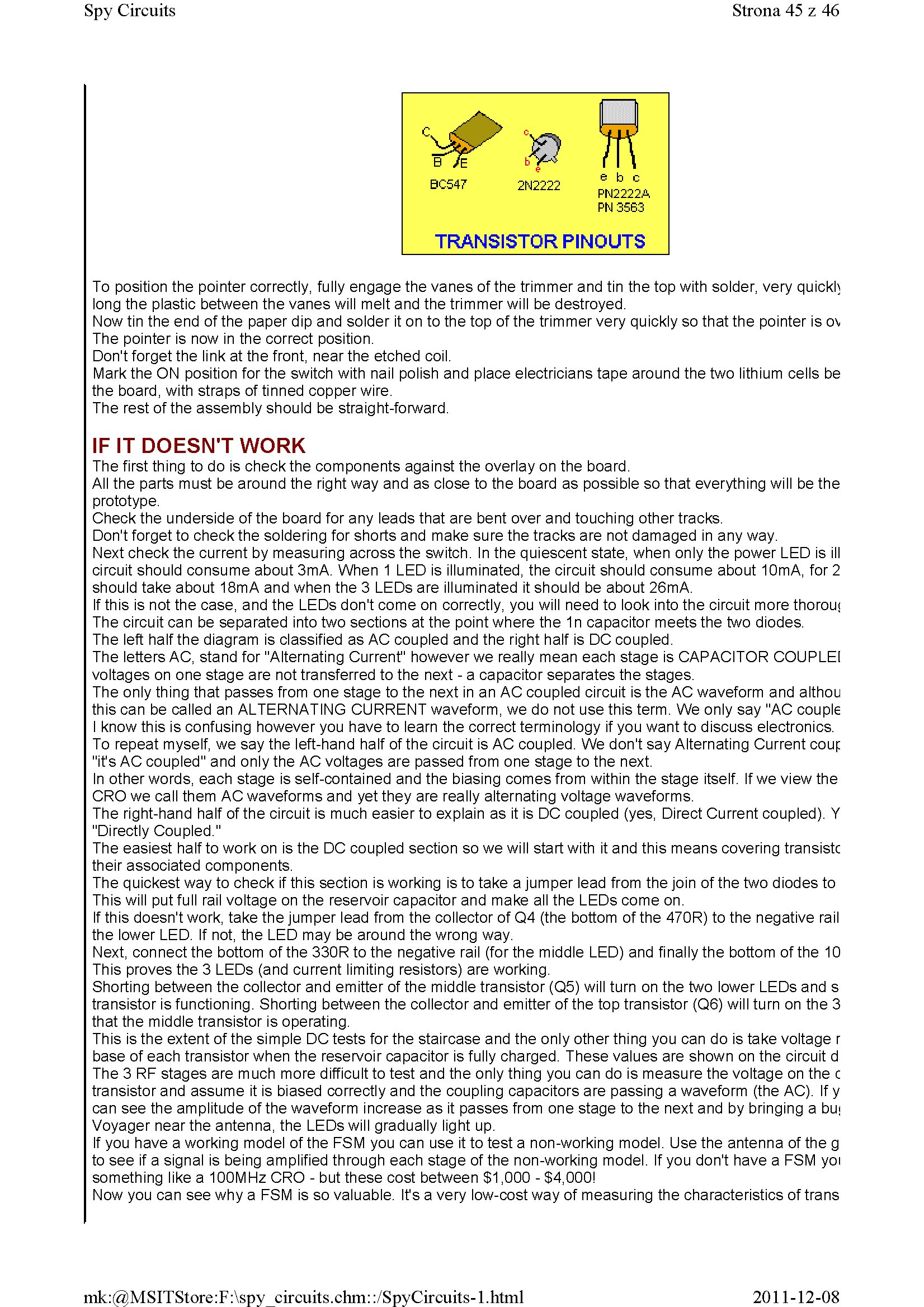
BC547 |
2N2222 |
e b c PN2222A PN 3563 | |
|
TRANSISTOR PINOUTS | |||
To position the pointer correctly, fully engage the vanes of the trimmer and tin the top with solder, very quickh long the plastic between the vanes will melt and the trimmer will be destroyed.
Now tin the end of the paper dip and solder it on to the top of the trimmer very quickly so that the pointer is o\ The pointer is now in the correct position.
Don't forget the link at the front, near the etched coil.
Mark the ON position for the switch with nail polish and place electricians tape around the two lithium cells be the board, with straps of tinned copper wire.
The rest of the assembly should be straight-forward.
IFITDOESNT WORK
The first thing to do is check the components against the overlay on the board.
Ali the parts must be around the right way and as close to the board as possible so that everything will be the prototype.
Check the underside of the board for any leads that are bent over and touching other tracks.
Don't forget to check the soldering for shorts and make surę the tracks are not damaged in any way.
Next check the current by measuring across the switch. In the quiescent State, when only the power LED is ill Circuit should consume about 3mA. When 1 LED is illuminated, the Circuit should consume about 10mA, for 2 should take about 18mA and when the 3 LEDs are illuminated it should be about 26mA.
If this is not the case, and the LEDs don't come on correctly, you will need to look into the Circuit morę thorou< The Circuit can be separated into two sections at the point where the 1n capacitor meets the two diodes.
The left half the diagram is classified as AC coupled and the right half is DC coupled.
The letters AC, stand for "Alternating Current" however we really mean each stage is CAPACITOR COUPLEI voltages on one stage are not transferred to the next - a capacitor separates the stages.
The only thing that passes from one stage to the next in an AC coupled Circuit is the AC waveform and althou this can be called an ALTERNATING CURRENT waveform, we do not use this term. We only say "AC couple I know this is confusing however you have to learn the correct terminology if you want to discuss electronics. To repeat myself, we say the left-hand half of the Circuit is AC coupled. We don't say Alternating Current coup "it's AC coupled" and only the AC voltages are passed from one stage to the next.
In other words, each stage is self-contained and the biasing comes from within the stage itself. If we view the CRO we cali them AC waveforms and yet they are really alternating voltage waveforms.
The right-hand half of the Circuit is much easier to explain as it is DC coupled (yes, Direct Current coupled). Y "Directly Coupled."
The easiest half to work on is the DC coupled section so we will start with it and this means covering transistc their associated components.
The quickest way to check if this section is working is to take a jumper lead from the join of the two diodes to This will put fuli raił voltage on the reservoir capacitor and make all the LEDs come on.
If this doesn't work, take the jumper lead from the collector of Q4 (the bottom of the 470R) to the negative raił the lower LED. If not, the LED may be around the wrong way.
Next, connectthe bottom of the 330R to the negative raił (for the middle LED) and finally the bottom of the 10 This proves the 3 LEDs (and current limiting resistors) are working.
Shorting between the collector and emitter of the middle transistor (Q5) will tum on the two lower LEDs and s transistor is functioning. Shorting between the collector and emitter of the top transistor (Q6) will turn on the 3 that the middle transistor is operating.
This is the extent of the simple DC tests for the staircase and the only other thing you can do is take voltage r base of each transistor when the reservoir capacitor is fully charged. These values are shown on the Circuit d The 3 RF stages are much morę difficult to test and the only thing you can do is measure the voltage on the c transistor and assume it is biased correctly and the coupling capacitors are passing a waveform (the AC). If y can see the amplitudę of the waveform increase as it passes from one stage to the next and by bringing a bu< Voyager near the antenna, the LEDs will gradually light up.
If you have a working model of the FSM you can use it to test a non-working model. Use the antenna of the g to see if a signal is being amplified through each stage of the non-working model. If you don't have a FSM yoi something like a 100MHz CRO - but these cost between $1,000 - $4,000!
Now you can see why a FSM is so valuable. It's a very low-cost way of measuring the characteristics of trans
2011-12-08
mk:@MSITStore:F:\spy circuits.chm::/SpyCircuits-l.html
Wyszukiwarka
Podobne podstrony:
1 (175) Spy Circuits Strona 36 z 46 Field Strength Meter Mkl Circuit. A 2N2222A transistor can be us
1 (152) Spy Circuits Strona 13 z 46 See the layout below: Faults with this Circuit: 1. Load resistor
1 (158) Spy Circuits Strona 19 z 46 /Antenna I 165cm A PNP in the buffer is not a good performer6. W
1 (164) Spy Circuits Strona 25 z 46 10p 166R 22p 75R 47 p 35R 1n 1R6 22n much less
1 (174) Spy Circuits Strona 35 z 46 A close-up of the Field Strength Meter Mkl connected to a multim
1 (177) Spy Circuits Strona 38 z 46 1 - BC 547 transistor 1 - PN 3563 RF transisto
1 (143) Spy Circuits Strona 4 z 46 illuminate. So far we have seen an unstable Circuit in action. Pi
1 (146) Spy Circuits Strona 7 z 46 The finished bug with "studs" for the battery and a cut
1 (148) Spy Circuits Strona 9 z 46 Antenna The emitter resistor is too Iow Inductor is 6 tums of wir
1 (140) Spy Circuits Strona 1 z 46by Colin Mitchell ITallltoti Notę: Ali the circuits described in t
1 (153) Spy Circuits Strona 14 z 46The Circuit on proto-typing board - a quick way to build a projec
1 (156) Spy Circuits Strona 17 z 46Use an RF transistor for the Buffer3. MORĘ RANGĘ Morę output can
1 (181) Strona 42 z 46 Spy Circuits coil. Ali the othertransmitters have sufficient output to detect
1 (141) Strona 2 z 46 Spy Circuits These circuits are very powerful, in that they are very hard to d
1 (142) Strona 3 z 46 Spy Circuits pulse is amplified by the transistor and the Circuit is kept acti
1 (147) Strona 8 z 46 Spy CircuitsAN IMPROVED DESIGN This design uses a "sług tuned coil"
1 (149) Strona 10 z 46 Spy Circuits2 TRANSISTOR CIRCUITS The next progressive step is to add a trans
1 (150) Strona 11 z 46 Spy Circuits magnetic field" and this occurs when the coil collapses and
1 (151) Strona 12 z 46 Spy Circuits - 5v for maximum output. The Voyager has been copied by many kit
więcej podobnych podstron