uchyby pomiarowe liczników cyfrowych009

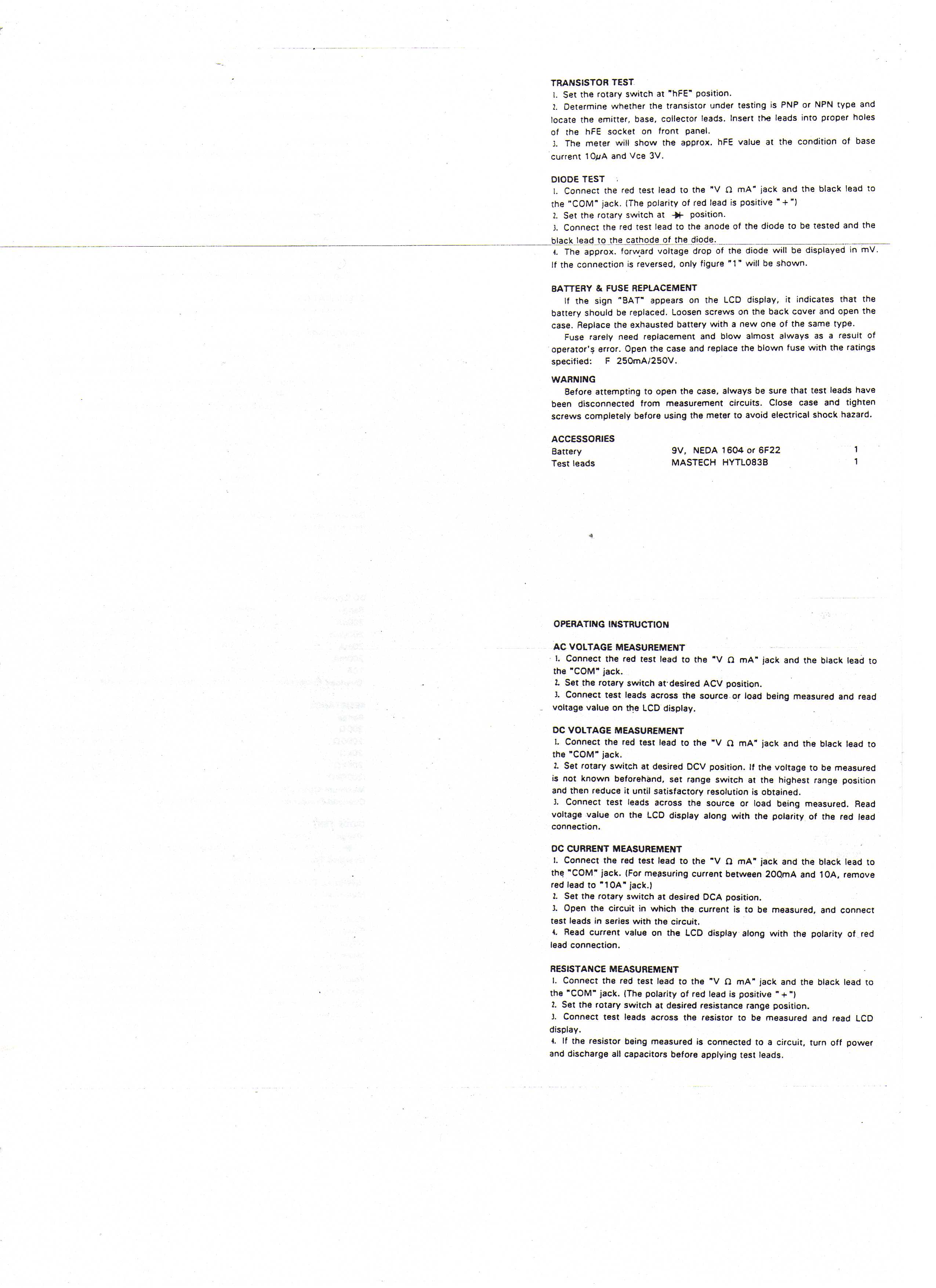
TRANSISTOR TEST
1. Set the rotary switch at "hFE" position.
2. Determine whether the transistor under testing is PNP or NPN type and locate the emitter, base, collector !eads. Insert the leads into proper holes of the hFE socket on front panel.
3. The meter will show the approx. hFE value at the condition of base current 10*/A and Vce 3V.
DIODĘ TEST
1. Connect the red test lead to the "V n mA" jack and the black lead to the "COM" jack. (The polarity of red lead is positive " + ")
2. Set the rotary switch at -W- position.
3. Connect the red test lead to the anodę of the diodę to be tested and the
black lead to the cathode of the diodę.____^
4. The approx. forward voltage drop of the diodę will be displayed in mV. If the connection is reversed, only figurę "1" will be shown.
BATTERY & FUSE REPLACEMENT
If the sign "BAT" appears on the LCD display, it indicates that the battery should be replaced. Loosen screws on the back cover and open the case. Replace the exhausted battery with a new one of the same type.
Fuse rarely need replacement and blow almost always as a result of operator'? error. Open the case and replace the blown fuse with the ratings specified: F 250mA/250V.
WARNING
Before attempting to open the case, always be surę that test leads have been disconnected from measurement circuits. Close case and tighten screws completely before using the meter to avoid electricał shock ha2ard.
ACCESSORIES
Battery 9V, NEDA 1604 or 6F22 1
Test leads MASTECH HYTL083B 1
OPERATING INSTRUCT10N AC VOLTAGE MEASUREMENT
1. Connect the red test lead to the "V O mA" jack and the black lead to the "COM" jack.
2. Set the rotary switch at-desired ACV position.
3. Connect test leads across the source or load being measured and read voitage value on the LCD display.
DC VOLTAGE MEASUREMENT
L Connect the red test lead to the "V a mA" jack and the black lead to the "COM" jack.
2. Set rotary switch at desired DCV position. If the voltage to be measured is not known beforehand, set rangę switch at the highest rangę position and then reduce it until satisfactory resolution is obtained.
3. Connect test leads across the source or load being measured. Read voltage value on the LCD display along with the polarity of the red lead connection.
DC CURRENT MEASUREMENT
1. Connect the red test lead to the "V O mA" jack and the black lead to the "COM" jack. (For measuring current between 200.mA and 10A, remove red lead to "10A" jack.)
2. Set the rotary switch at desired DCA position.
3. Open the Circuit in which the current is to be measured, and connect test leads in series with the Circuit.
4. Read current value on the LCD display along with the polarity of red lead connection.
RESISTANCE MEASUREMENT
1. Connect the red test lead to the "V O mA" jack and the black lead to the "COM" jack. (The polarity of red lead is positive " + ")
2. Set the rotary switch at desired resistance rangę position.
3. Connect test leads across the resistor to be measured and read LCD display.
4. If the resistor being measured is connected to a Circuit, turn off power and discharge all capacitors before applying test leads.
Wyszukiwarka
Podobne podstrony:
uchyby pomiarowe liczników cyfrowych010 • Never use the meter unless the back cove
uchyby pomiarowe liczników cyfrowych001 UCHYBY POMIAROWE MIERNIKÓW CYFROWYCHTablica 1 Miernik V561
uchyby pomiarowe liczników cyfrowych005 Miernik METEX M-3890D ’* Funkcja Zakres Rozdzielczość C Ni
uchyby pomiarowe liczników cyfrowych006 Miernik METEX M3830 i M3850 Funkcja Zakres ,,,■, ,-Rozdzie
uchyby pomiarowe liczników cyfrowych007 Miernik METEX M3800
uchyby pomiarowe liczników cyfrowych008 Miernik METEX MY-67 1 Funkcja Zakres Rozdzielczość C Niepe
uchyby pomiarowe liczników cyfrowych011 i Miernik M-830B Funkc ja Zakres Rozdzielczość Niepewność
uchyby pomiarowe liczników cyfrowych002 Miernik METEX-80 i Funkcja 1 — ■ nrr— Zakres Rozdzielczość
uchyby pomiarowe liczników cyfrowych004 Miernik METEX M4650 i M4550 CR i Funkcja Zakres Rozdzielcz
uchyby pomiarowe liczników cyfrowych012 Miernik METEX MY-62 i MY-64 Funkcja Napięcie stałe DC Zakres
12 pcx VI 14626(N) 3/4 VI 14626(N) 3/4Notę: • Set the following switch or On-screen menu to the posi
14 pcx AI-14526IN) 2/2Notes: • Set the following switch or On-screen menu to the positions indicator
2) Tum the " TRAESPOSE " switch to ”LW position. Press down the PI key, a pulse wave seen
00457 ?c9724a5349b9ca020fa0b800a81195 462 Russell The Geophysical Sonic Log Data Set The author s f
więcej podobnych podstron