Page12
12
Control system
0= _360=_720= KW |
|
1 Ignition sequence of the cylinders 4 and opening times of the inlet valves 3 2 |
I |
1- 1 r | ||||
|
I |
1 | |||||
|
1 |
1 | |||||
|
1 |
1 | |||||
|
Ignition delivers trigger pulses |
W |
U | ||||
|
Pulse shaper aenerates rectangular pulses |
1 | |||||
|
Frequency divider halves the impulse period in order to control the injection valves | ||||||
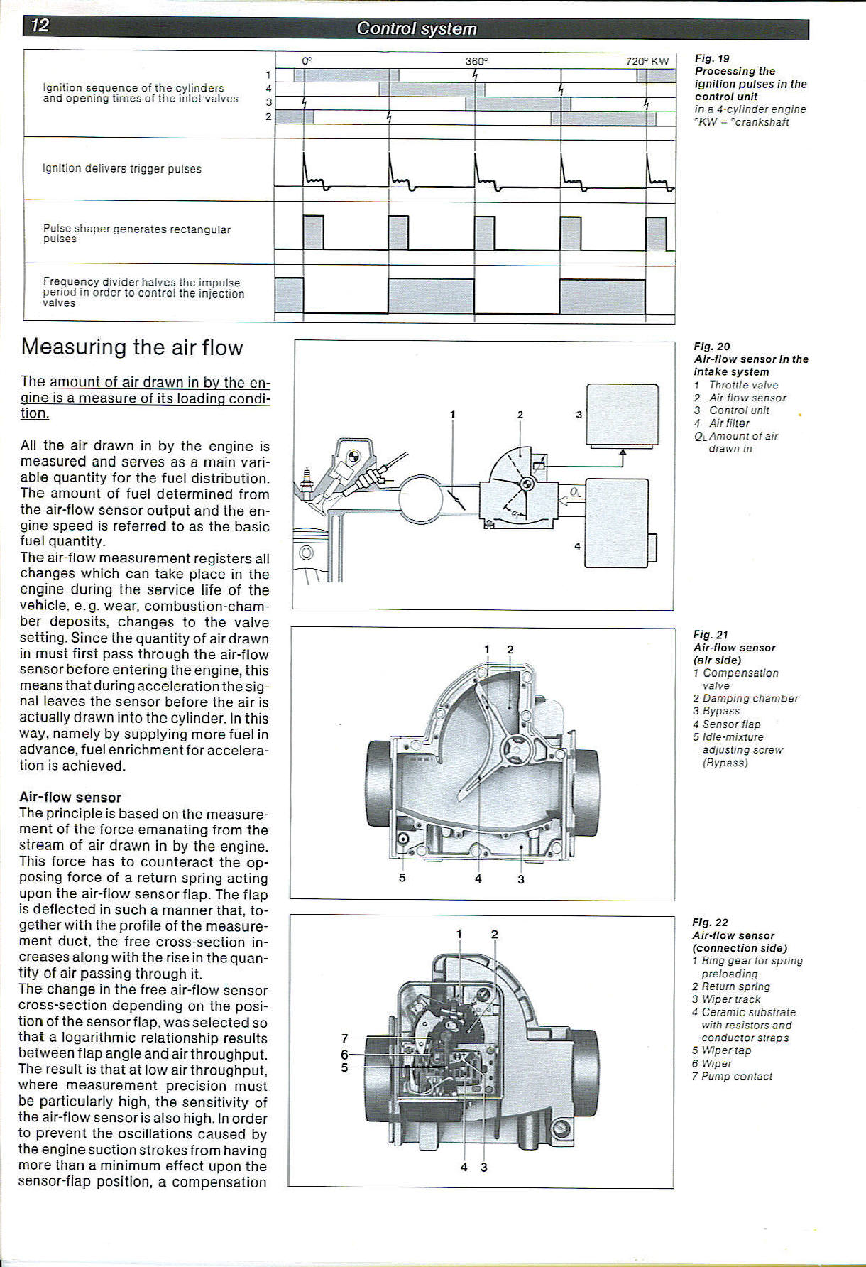
Fig. 19
Processing the ignition pulses in the control unit
in a 4-cylinder engine -KW = =crankshaft
Measuring the airflow
The amount of air drawn in bv the engine is a measure of its loading condi-tion.
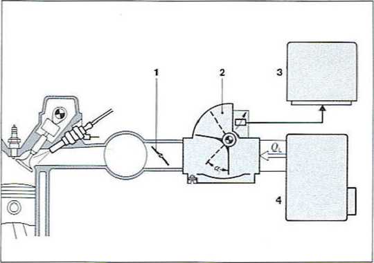
Fig. 20
Air-flow sensor in the intake system
1 Throttle valve
2 Air-flow sensor
3 Control unit
4 Air tUter
Ol Amount of air drawn in
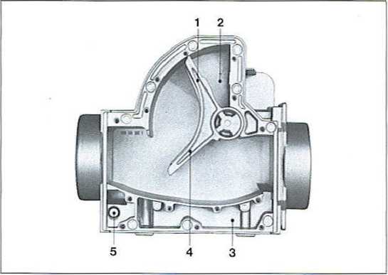
Fig. 21
Air-flow sensor (air side)
1 Compensation valve
2 Camping chamber
3 Bypass
4 Sensorflap
5 idie-mixture adjusting screw (Bypass)
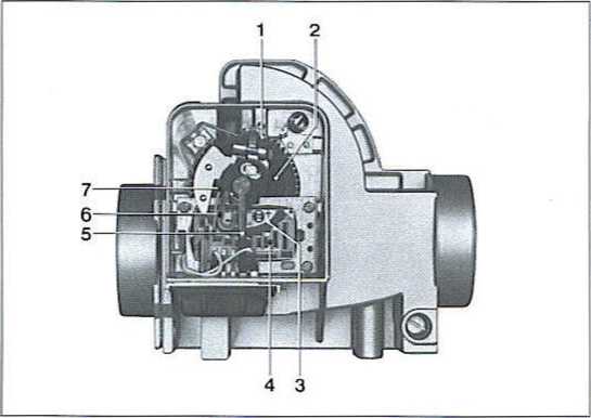
Fig. 22
Air-flow sensor
(connection side)
1 Ring gear for spring preloading
2 Return spring
3 Wipertrack
4 Ceramic substrate with resistors and conductor straps
5 Wiper tap
6 Wiper
7 Pump contact
Ali the air drawn in by the engine is measured and serves as a main vari-able quantity for the fuel distribution. The amount of fuel determined from the air-flow sensor output and the engine speed is referred to as the basie fuel quantity.
The air-flow measurement registers all changes which can take place in the engine during the service life of the vehicle, e.g. wear, combustion-cham-ber deposits, changes to the valve setting. Since the quantity of air drawn in must first pass through the air-flow sensor before entering the engine, this means that during acceleration the sig-nal leaves the sensor before the air is actually drawn into the cylinder. In this way, namely by supplying morę fuel in advance, fuel enrichment for acceleration is achieved.
Air-flow sensor
The principle is based on the measurement of the force emanating from the stream of air drawn in by the engine. This force has to counteract the op-posing force of a return spring acting upon the air-flow sensor flap. The flap is deflected in such a mannerthat, to-gether with the profile of the measurement duet, the free cross-section in-creases along with the rise in the quan-tity of air passing through it.
The change in the free air-flow sensor cross-section depending on the posi-tion of the sensorflap, was selected so that a logarithmic relationship results between flap angle and airthroughput. The result is that at Iow air throughput, where measurement precision must be particularly high, the sensitivity of the air-flow sensor is also high. In order to prevent the oscillations caused by the engine suction strokes from having morę than a minimum effect upon the sensor-flap position, a compensation
Wyszukiwarka
Podobne podstrony:
Page12 12Control system 0= _360=_720= KW
Page12 12Control system 0= _360=_720= KW
netter60 Electrocardiogram: IIICARDIOVASCULAR PHYSIOLOGY Norm.il Sequence of Cardiac Depolarization
5 EXAMPLES 5.1 STRENGTH ASSESSMENT BASED ON BIENIAWSKPS ROCK MASS RATING SYSTEM RMR„. As an example
Table 1. Amino acid sequence of the glycoprotein of G mutants. Amino acid differences between the gl
61666 system 16 16 tlie blind credulity of the public. There does not exist any hocu9-pocus, witchcr
CZYM JEST BIOLOGIA SYSTEMÓW? “Integrate data from multiple levels of the biological information hier
37188 system 116 110FOOT EXERGISE No. 2.—Rotation of the Feet While the leg is kept stationary, the
ZINTEGROWANY SYSTEM WIZYJNY Szerokie spektrum funkcjonalności i HEMBER OF THE A88 6R3UP »•r -
dsc00134 (12) YVr«»tŁm L)rr.r*rufv«* ?ohrvWofflKomputery IBM system 360 • Nowa rod
00023 ?af22c93872cf7ae27cedeca48403b7 22 Molnau value of 4.2. The system performed slightly better
00039 ?0994c0b89c0edd69cbdfecf717cc9b 38 Molnau OPS5 (Official Production System, Version 5) is a w
więcej podobnych podstron