Page14
14
Control system
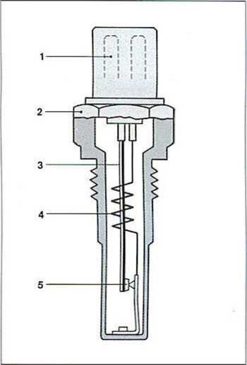
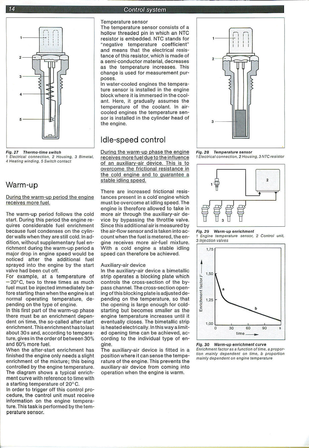
Fig. 27 Thermo-time switch
1 Electrical connection, 2 Housing, 3 Bimetal, 4 Heating winding. 5 Switch contact
Warm-up
During the warm-up period the engine receives morę fuel.
The warm-up period follows the cold start. During this period the engine re-quires considerable fuel enrichment because fuel condenses on the cylinder walls when they arestill cold. In ad-dition, without supplementary fuel enrichment during the warm-up period a major drop in engine speed would be noticed after the additional fuel sprayed into the engine by the start valve had been cut off.
For example, at a temperaturę of — 20°C, two to three times as much fuel must be injected immediately be-fore starting than when the engine is at normal operating temperaturę, de-pending on the type of engine.
In this first part of the warm-up phase there must be an enrichment dependent on time, the so-called after-start enrichment. This enrichment has to last about 30s and, according to temperaturę, gives in the order of between 30% and 60% morę fuel.
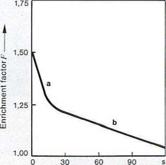
When the after-start enrichment has finished the engine only needs a slight enrichment of the mixture; this being controlled by the engine temperaturę. The diagram shows a typical enrichment curve with reference to time with a starting temperaturę of 20°C.
In order to trigger off this control procedurę, the control unit must receive information on the engine temperaturę. This task is performed by the temperaturę sensor.
Temperaturę sensor The temperaturę sensor consists of a hollow threaded pin in which an NTC resistor is embedded. NTC stands for “negative temperaturę coefficient" and means that the electrical resis-tance of this resistor, which is madę of a semi-conductor materiał, decreases as the temperaturę increases. This change is used for measurement pur-poses.
In water-cooled engines the temperaturę sensor is installed in the engine błock where it is immersed in the cool-ant. Here, it gradually assumes the temperaturę of the coolant. In air-cooled engines the temperaturę sensor is installed in the cylinder head of the engine.
Idle-speed control
During the warm-up phase the engine receives morę fuel due to the influence of an auxiliarv-air device. This is to oyercome the frictional resistance in the cold engine and to guarantee a stable idling speed.
There are increased frictional resis-tances present in a cold engine which must be oyercome at idling speed. The engine is therefore allowed to take in morę air through the auxiliary-air de-vice by bypassing the throttle valve. Since this additional air is measured by the air-f Iow sensor and is taken into ac-count when the fuel is metered, the engine receives morę air-fuel mixture. With a cold engine a stable idling speed can therefore be achieved.
Auxiliary-air device In the auxiliary-air device a bimetallic strip operates a blocking piąte which Controls the cross-section of the by-pass channel. The cross-section open-ing of this blocking piąte is adjusted de-pending on the temperaturę, so that the opening is large enough for cold-starting but becomes smaller as the engine temperaturę increases until it eventually closes. The bimetallic strip is heatedelectrically. In this way alimit-ed opening time can be achieved, according to the individual type of engine.
The auxiliary-air device is fitted in a position where i t can sense the temperaturę of the engine. This prevents the auxiliary-air device from coming into operation when the engine is warm.
|
1-- |
-' /- I I h i : i i i i |
1 1 1 |
|
2-(5 | ||
|
] N 3 - |
TT | |
Fig. 28 Temperaturę sensor
1 Electrical connection. 2 Housing, 3 NTC resistor
|
i 1 £- I |
2 J. | ||
|
f^f |
i fd | |
? | |
Fig. 29 Warm-up enrichment
1 Engine temperatura sensor, 2 Control unit, 3 Injection valves
time
Fig. 30 Warm-up enrichment curve
Enrichment iactoras a function o i time. a propor-tion mainly dependent on time, b proportion mainly dependeni on engine temperatura
Wyszukiwarka
Podobne podstrony:
Page15 15 Control system n -; I ^ V V r
89787 Page11 11 Contro! system Fig. 18 Calculating engine speed with a breaker-triggered ignition sy
Tracking errors decreasing in CNC system of machinę tools 89 Fig. 3. The architecture of CNC control
slajd15 RBCEIYER Traek codę and phase Compute position CONTROL SYSTEM Time synchronization Orbit
System MTTR1 Common repair time lndividual repair time Time Classification i ffl Controlled by overa
furby kolorowanka (27) 1. GAMĘ TIME Furty want® to play a 33™® with fr!«ndik Help Furty reach by f
Slajd22 (159) MCF5407- WŁASNOŚCI ♦ System debug support — Real-t
więcej podobnych podstron