89787 Page11
11
Contro! system
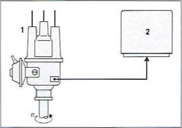
Fig. 18 Calculating engine speed with a breaker-triggered ignition system
n engine speed. 1 ignition distributor. 2 control unit
Input auantities Control unit and Output quantities
supply
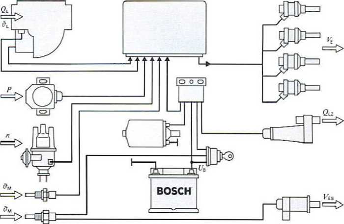
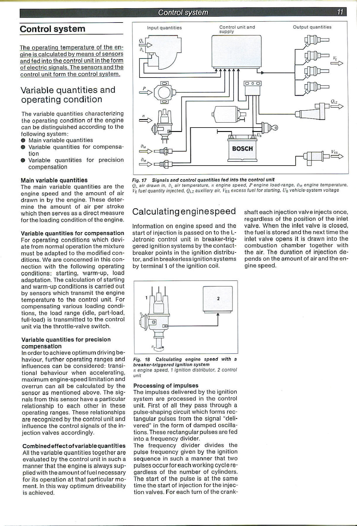
Fig. 17 Signals and control quantities fed into the control unit
Ql air drawn in. trL air temperaturę, n engine speed. P engine load-range. Cu engine temperaturę. I'E luel guantity injected, Qn auxiliary air. CES excess luel lor starting. Uq vehicle-system yoltage
Control system
The operating temperaturę of the en-gine is calculated by means of sensors and fed into the control unitin the form of electric signals. The sensors and the control unit form the control system.
Variable quantities and operating condition
The variable quantities characterizing the operating condition of the engine can be distinguished according to the following system:
© Main variable quantities ® Variable quantities for compensa-tion
• Variable quantities for precision compensation
Main variable quantities
The main variable quantities are the engine speed and the amount of air drawn in by the engine. These deter-mine the amount of air per stroke which then serves as a direct measure forthe loading condition of the engine.
Variable quantities for compensation
For operating conditions which devi-ate from normal operation the mixture must be adapted to the modified conditions. We are concerned in this con-nection with the following operating conditions: starting, warm-up, load adaptation. The calculation of starting and warm-up conditions is carried out by sensors which transmit the engine temperaturę to the control unit. For compensating various loading conditions, the load rangę (idle, part-load, full-load) is transmitted to the control unit via the throttle-valve switch.
Variable quantities for precision compensation
In orderto achieve optimum driv ing be-haviour, further operating ranges and influences can be considered: transi-tional behaviour when accelerating, maximum engine-speed limitation and overrun can all be calculated by the sensor as mentioned above. The signals from this sensor have a particular relationship to each other in these operating ranges. These relationships are recognized by the control unit and influence the control signals of the in-jection valves accordingly.
Combinedeffectofvariablequantities
All the variable quantities together are evaluated by the control unit in such a manner that the engine is always sup-plied with the amount offuel necessary for its operation at that particular moment. In this way optimum driveability is achieved.
Calculatingenginespeed
Information on engine speed and the start of injection is passed on to the L-Jetronic control unit in breaker-trig-gered ignition systems by the contact-breaker points in the ignition distribu-tor, and in breakerless ignition systems by terminal 1 of the ignition coil.
Processing of impulses
The impulses deiivered by the ignition system are processed in the control unit. First of all they pass through a pulse-shaping Circuit which forms rec-tangular pulses from the signal “deli-vered” in the form of damped oscilla-tions. These rectangular pulses are fed into a frequency divider.
The frequency divider divides the pulse frequency given by the ignition sequence in such a manner that two pulses occurforeach working cycle re-gardless of the number of cylinders. The start of the pulse is at the same time the start of injection for the injection valves. For each turn of the crank-shaft each injection valve injects once, regardless of the position of the inlet valve. When the inlet valve is closed, the fuel is stored and the next time the inlet valve opens it is drawn into the combustion chamber together with the air. The duration of injection de-pends on the amount of airand the engine speed.
Wyszukiwarka
Podobne podstrony:
11 (179) Fig. 18-4 Osteopetrosis. Lateral skuli radiograph shows dense calcification of ja
Tracking errors decreasing in CNC system of machinę tools 89 Fig. 3. The architecture of CNC control
wtkmmte ZINTEGROWANY SYSTEM ZARZĄDZANIA FBP-11-01-01 Strona 18 z 26 Zarządzanie ryzykiem
Page15 15 Control system n -; I ^ V V r
Page14 14 Control system Fig. 27 Thermo-time switch 1 Electrical connection, 2 Housing, 3 Bimetal, 4
skanuj0021 (63) 11. K. Pajęcki System polityczny - całość złożona z dwóch podsyste
więcej podobnych podstron