CT2137!57SM djvu
AK Al seruice iramuRi
BHMMAHME!!!3Ta cxeMa HE npeflHa3HaHeHa fljin npo^a^CH Ha ,a,MCKax.CxeMy moacho cboóoaho nonynMTb Ha caiiTe
' ’'www. r adiolom. by. r u" (www. hot. ee/ j uden 001/).Ec;im Błi ee KynuTin Ha 6ojiBaHKe,TO Bac KanMTa^bHO Hae6;m!He no^^epHiMBaMTe 3tmx nM^opOB-ToproBH^eB Kpa^eHHbiM!!!
WARNINGIHThis scheme not for selling on CD,its possible liberally get on put www.radiolom.by.ru.If You have sold this scheme on CD,that You have well defrauded.Do Not buy the thieved belongingsIThe Death thief!
COLOUR TELEVISION
MODEL CT-21 37f/ukt
MODEL CT-21 57D/DT/E/ET/F/P/PT/UKT
SPECIFICATIONS
|
Broadcasting form |
System BG......................... |
... VHF : ch 2 - 12 | |
|
2157D/DT..................... |
.....BG,DK PAL-SECAM |
UHF : ch 21 -69 | |
|
2157E/ET..................... |
.....BG PAL-SECAM |
Cable : ch S01 - S03, | |
|
2137F, 2157F................ |
.....BG,I,LL PAL-SECAM |
S1 - S41 | |
|
2157P/PT..................... |
.....PAL BG |
System I............................. |
... UHF : ch 21 -69 |
|
2137UKT, 2157UKT..... |
.....PAL I |
VHF : 1A -1J (Ireland) | |
|
Selection form.................. |
.....Infra-red remote contro! |
Cable : S01 - S03, S1 - S41 | |
|
Programme channel......... |
.....60 |
2137UKT, 2157UKT | |
|
Receive channel |
System I............................. |
... UHF : ch 21 -69 | |
|
2157D/DT System BG................ |
.....VHF : ch 2 -12 |
VHF : 1A -1J (Ireland) Cable : S01 - S03, S1 - S41 | |
|
UHF : ch 21 - 69 |
Musie power.............................. |
...5 W RMS | |
|
System DK................ |
Cable : ch S01 - S03, S1 - S41 .....VHF : R1 - RX11, 4-9 |
Power requirement 2137UKT, 2157UKT............... |
...230 V-240 V AC, 50 Hz |
|
UHF : ch 21 - 69 |
Except 2137UKT, 2157UKT.. |
... 230 V AC, 50 Hz | |
|
2157E/ET,2157P/PT |
Power consumption.................. |
...60 W | |
|
System BG................ |
.....VHF : ch 2 - 12 |
CRT size...................................... |
... 21 inches (Picture : 51 cm) |
|
UHF : ch 21 - 69 |
Set dimensions............................. |
...530 (W) x 450 (H) x 474 (D) | |
|
2137F, 2157F |
Cable : ch S01 - S03, S1 - S41 |
Packing dimensions.................. |
mm ...600 (W) x 575 (H) x 565 (D) |
|
System LL................. |
.....VHF:ch2-4, 5-10 |
mm | |
|
UHF : ch 21 - 69 |
Weight....................................... |
...21 kg | |
|
Cable : ch B - Q |
Gross weight............................. |
...24 kg |
* For improvement purposes, specifications and design are subject to change without notice.
npofla>KM Ha flircKłijx.CxeMy mcWkho CBOÓdmHO nojiyHMTb Ha caiiT i "www.radiolom.b}
Bw ee KynMTiM Ha (iojiBaHKe,TO Bac KanMTanbHO Hae67iM!He no^e]** nM^opOB-ToproBi] eE
WARNING!!!This possible liberally §
You have sold this defrauded.Do Not Death thief!
5 | 6 | 7 | 8 1 9 1 10 | TT
_ ..__JDBACK
! n u n h
>MUE^SC.CH SATURi 2Ł.
lsi 1
«4 4 CS 4C6 Z.2UF z.Tuf z.ąl B3V B3V B3V
uu
aSwT
VIDEO
3 -

—Ig?
3ITRt
DTCM4TS A&


AGC
*
SI
mi
4R7 4»k
J.PH.D R.CUT<
.3. SB G.OUT (
-SŁ<yr.3.43 B.OUT
OSC.H Mli t.DRV CHR.I.SH
Y.SSC VID.I.EX
t-JMt-J X
•—ae
BCI
|
kCC.ADJ |
ido4T(S2 |
|
BJ.OUT |
TANKO^ |
|
tUD.D |
tanko^ |
|
aD.DEC |
AU.D/POL oI |
y^L.
m

tu.J
FILTRE0FHL94S3
AMD AMD
BHMMAHME!!!3Ta cxeMa HE npe^HasHaneHa npofta^KM Ha ,n;MCKax.CxeMy moacho cboóo^ho nonyuMTb HacaiiTe -———-

I...I! W SST7
b u s m a i n
b u s data
bus signa
"www.radiolqm.by.ru"(www.hot.ee/juden001/).Ecjm Bw ee KynMjiM Ha 6onBaHKe,To Bac KanMTanbHo Hae6jin!He no^^epHCMBanTe 3tmx nM^opoB-ToproBijeB Kpa^eHHbiM!!! WAKNING!!! I his scheme not tor selling on CU,its possible liberally get on put www.radiolom.by.ru.If You have sold this scheme on CD,that You have well
A „4-\.___A „A T\„ XT1______ +1. „ +u:^____4 1__1------ITU„
FRAME
-COHLENT --CR-
c
Ul
3P 7.a
|
--==- i |
R | ||
|
JSU_... DDtS |
7 1 | ||
|
(70 0. BRtB |
SM I2k q |
t |
_sJ |
|
°-=H ftSiF ,I | |||
ais
BTR99 , BC347B t
,43k
i2«i
10
AMD
AMD
TF fica.4
VR6PI: VERTICAL SIZE ADJ. VR6PZ:LINEARITY ADJ. VR6P3:VERTICAL PHASE ADJ.
SOCKET
DRIVER
SCREEN
BHMMAHME!!!3 cxeMa HE npe^HasHaneHa ^7 npo^a>Kii Ha 3MCKax.CxeMy MO)KHO CBOÓO^HO nOTiyHMTb Ha CaMT "www.radiolom.h) "(www.hot.ee/jud 1/).Ecjim Bw ee KynuTiM Ha 6oHBaHKe,TO Bac
T¥■
dnrt
i «/Tvihbio
CoWSłCMTS
KPUACE SAFETY CHITICAL COMPOHENTS OfŁT^HlTH nANUrWrmRtH-SRECOnrCMDI
CRITIOUCS DC SCCURITC.POUR fWlNTCNIR
“ FABRA1C^I
PROWJflET
>3-
JST Ł, o*-,
tn -l
ftVEHTlS3EMENT^t\ WD10UE LES COMPOSANTS

KanmajibHO Hae6;m!He no^^epHCMBaMTe 31tm|x nM^opOB-ToproBi^eBi Kpa^eHHbiM!!
WARNING!!!This scheme not for selling on CD,its possible liberally gjet on put
www.radiolom.by-m f You have sold th s scheme on CD.thaf
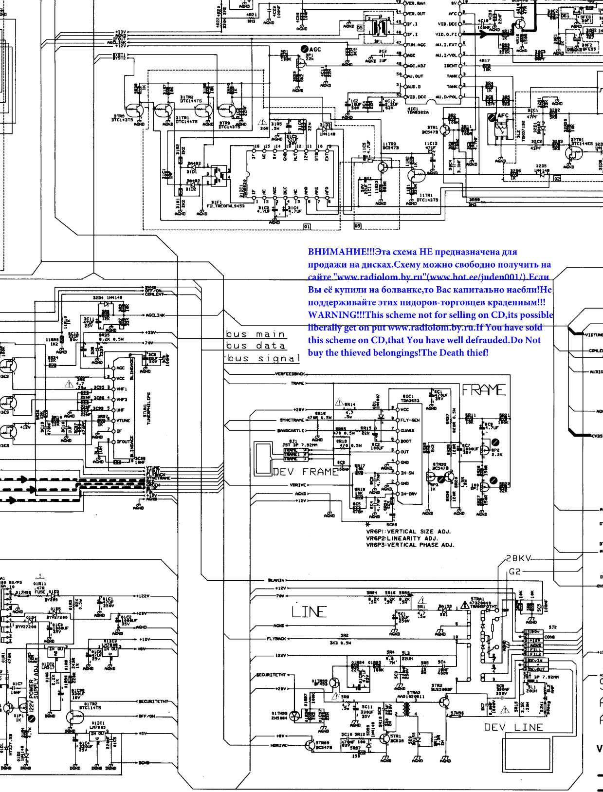
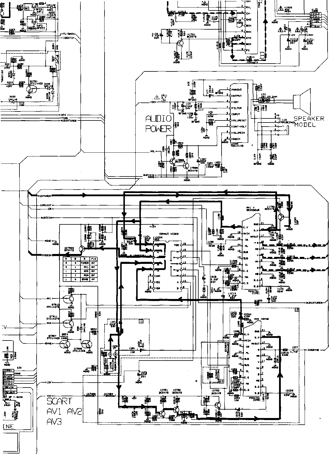
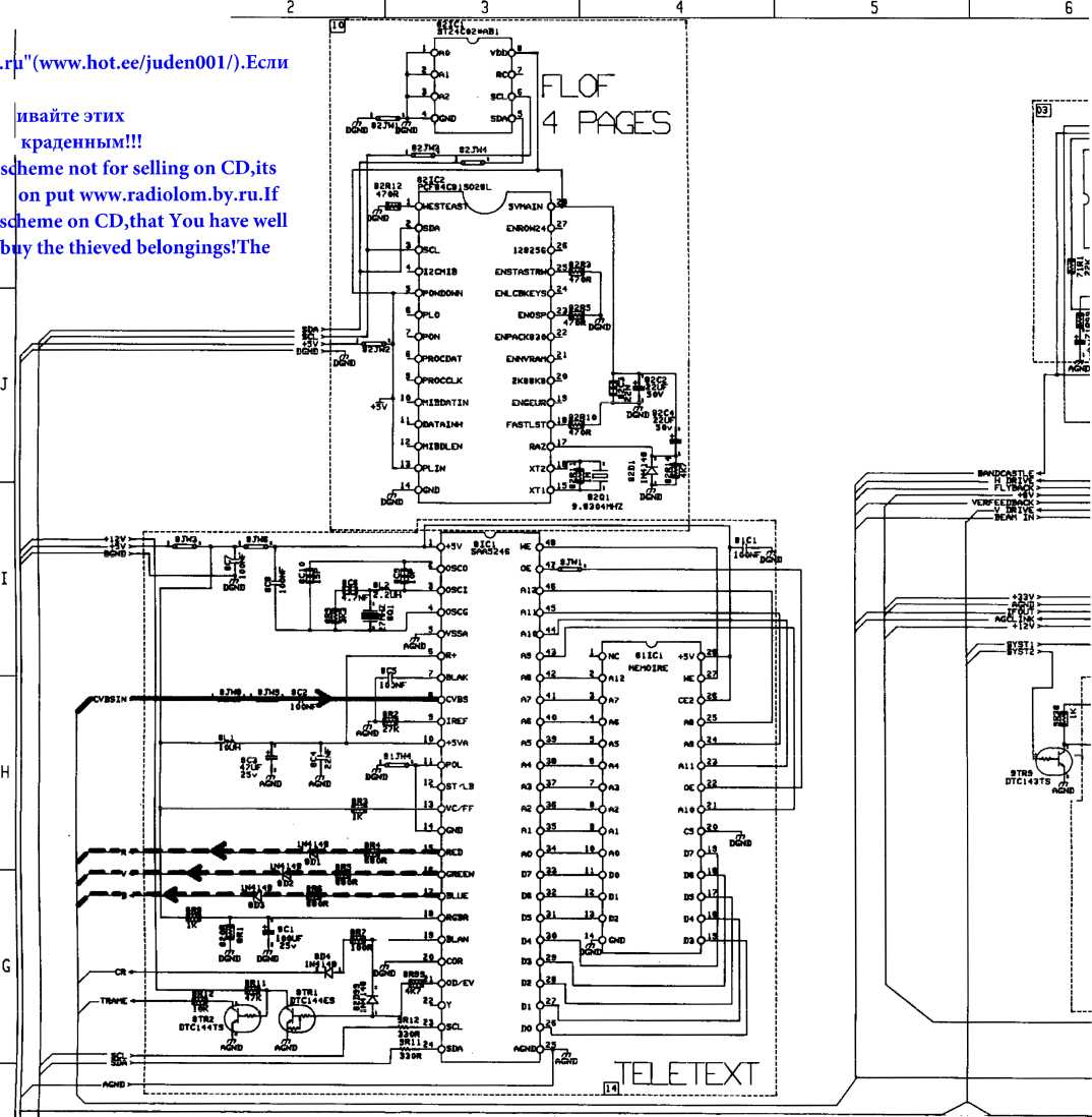
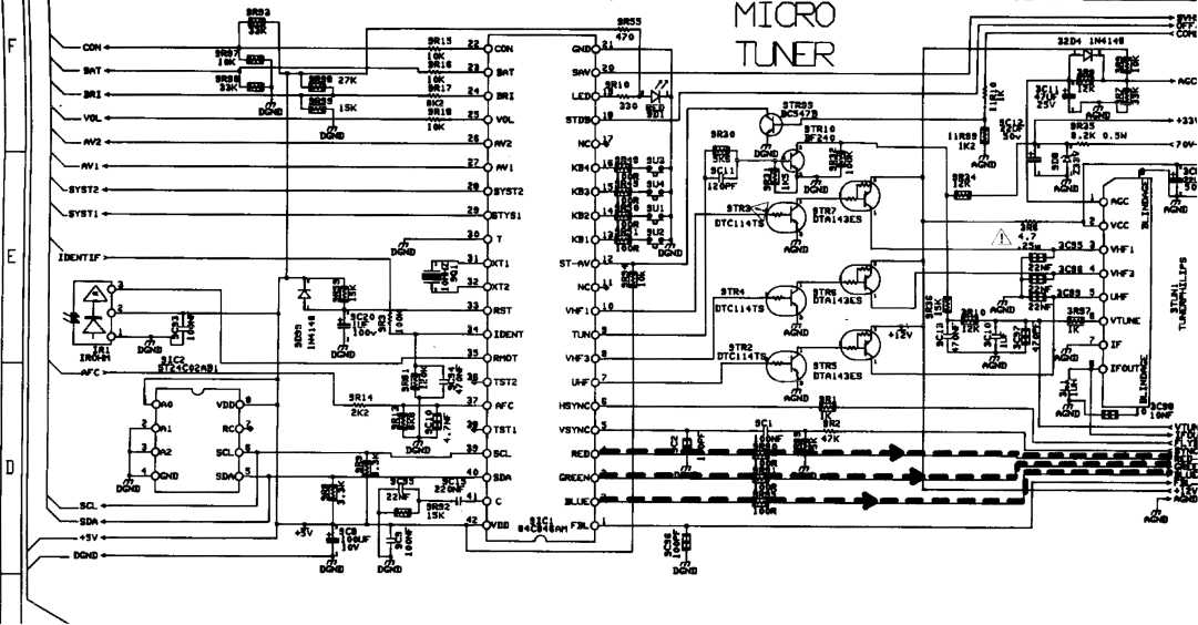
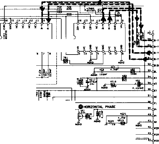
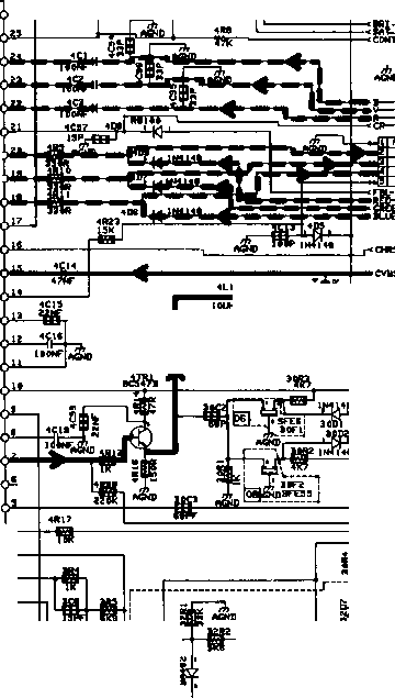
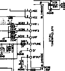
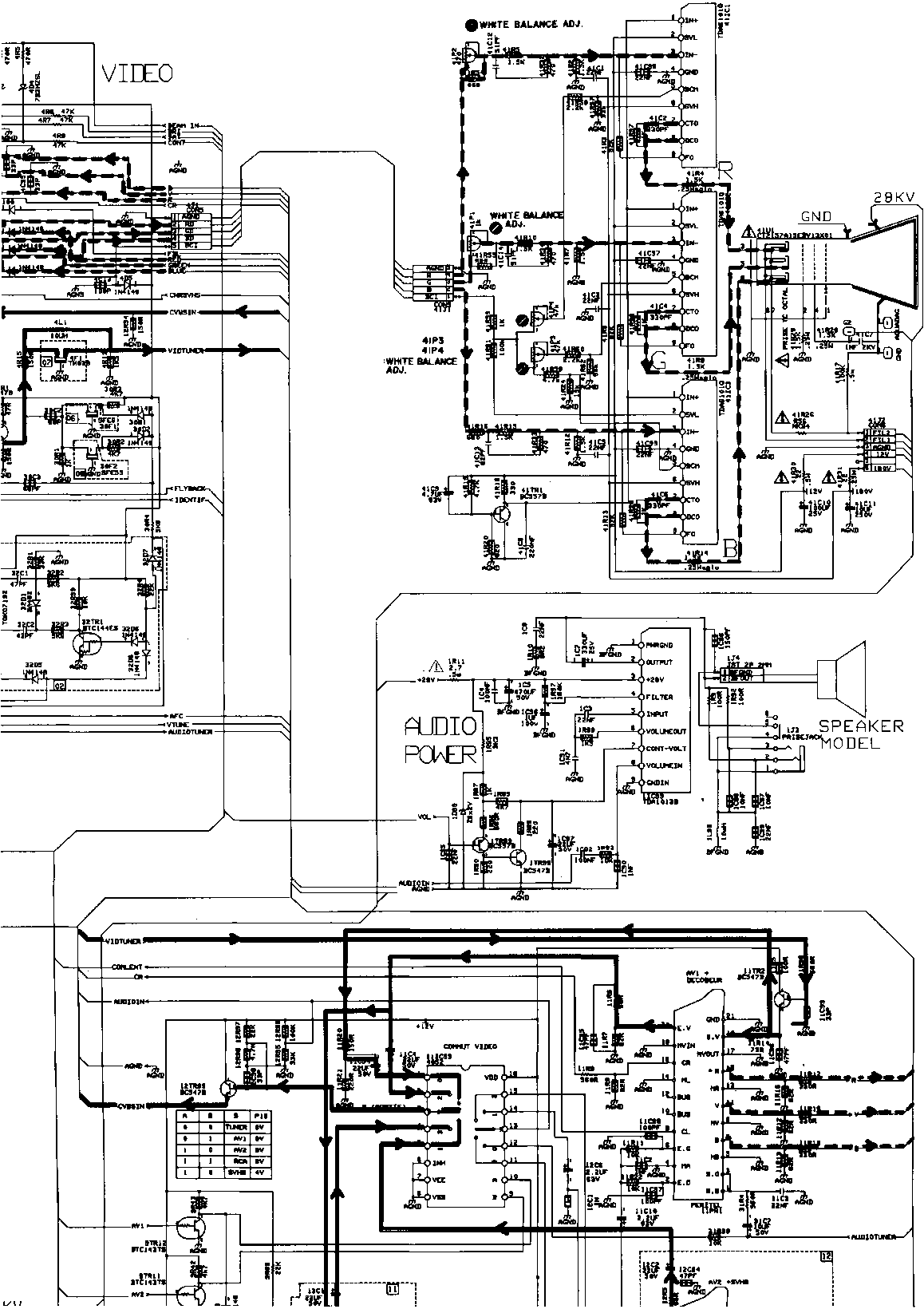
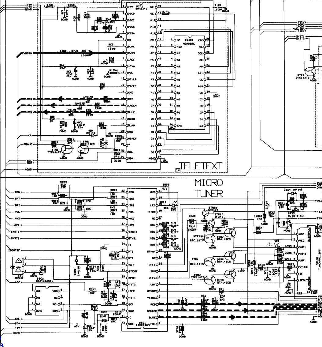
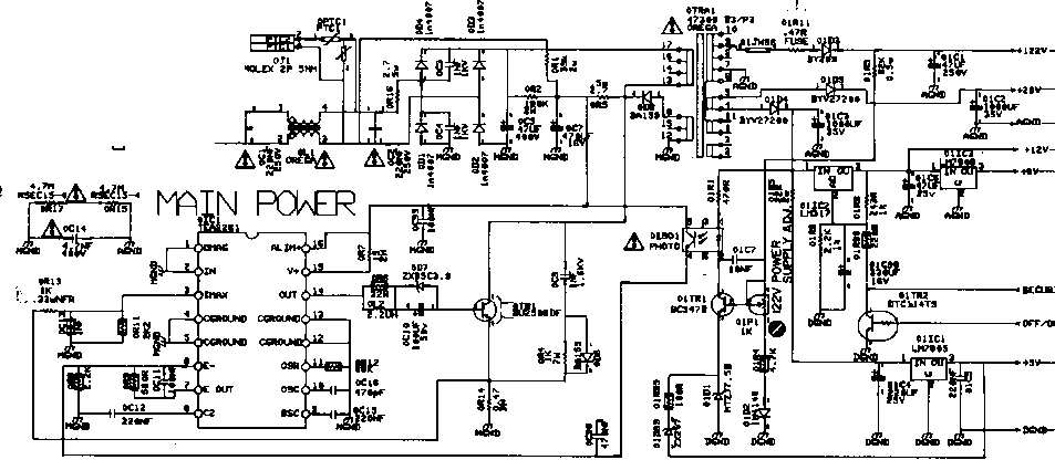
VI MAIN & SOCKET SCHEMATIC DIAGRAM
Video Signal Linę RGB Signal Linę
CT 2137 F/UKT
CT 2157 D/DT/E/ET/F/P/PT/UKT CTV Schematic diagram N° QF 001 F 301
I MEASURED YOLTAGES OF THE SEMICONDUCTORS
ICS
0IC1
4IC1
6IC1
8IC1
81101
9IC1
|
1 |
— |
|
2 |
— |
|
3 |
0.1 V |
|
4 |
— |
|
5 |
— |
|
6 |
2.4 V |
|
7 |
2.6 V |
|
8 |
0 V |
|
9 |
3.0 V |
|
10 |
2.4 V |
|
11 |
2.5 V |
|
12 |
— |
|
13 |
— |
|
14 |
1.1 V |
|
15 |
11.6 V |
|
16 |
12.9 V |
uiiCi
|
1 |
15.4 V |
|
2 |
— |
|
3 |
5.0 V |
01IC2
|
1 |
11.4 V |
|
2 |
17.4 V |
|
3 |
12.6 V |
01IC3
|
1 |
12.6 V |
|
2 |
— |
|
3 |
8.0 V |
1IC99
|
1 |
— |
|
2 |
14.3 V |
|
3 |
28.4 V |
|
3 |
14.2 V |
|
5 |
0 V |
|
6 |
0 V |
|
7 |
14.3 V |
|
8 |
0 V |
|
9 |
__ |
0IS01
|
1 |
16.5 V |
|
2 |
15.5 V |
|
3 |
0 V |
|
4 |
2.4 V |
|
5 |
12.9 V |
|
6 |
0 V |
|
1 |
3.2 V |
|
2 |
5.9 V |
|
3 |
5.9 V |
|
4 |
7.1 V |
|
5 |
1.6 V |
|
6 |
3.8 V |
|
7 |
3.2 V |
|
8 |
1.7 V |
|
9 |
4.7 V |
|
10 |
8.0 V |
|
11 |
— |
|
12 |
3.3 V |
|
13 |
4.4 V |
|
14 |
3.9 V |
|
15 |
3.8 V |
|
16 |
0.7 V |
|
17 |
1.2 V |
|
18 |
2.8 V |
|
19 |
2.6 V |
|
20 |
2.7 V |
|
21 |
3.3 V |
|
22 |
3.3 V |
|
23 |
3.3 V |
|
24 |
3.3 V |
|
25 |
2.1 V |
|
26 |
1.5 V |
|
27 |
5.8 V |
|
28 |
3.8 V |
|
29 |
3.8 V |
|
30 |
1.5 V |
|
31 |
1.5 V |
|
32 |
1.6 V |
|
33 |
4.8 V |
|
34 |
2.2 V |
|
35 |
2.0 V |
|
36 |
8.0 V |
|
37 |
4.4 V |
|
38 |
0.5 V |
|
39 |
3.1 V |
|
40 |
3.8 V |
|
41 |
— |
|
42 |
2.5 V |
|
43 |
2.6 V |
|
44 |
3.9 V |
|
45 |
4.0 V |
|
46 |
4.0 V |
|
47 |
7.8 V |
|
48 |
3.8 V |
|
49 |
1.9 V |
|
50 |
3.5 V |
|
51 |
4.7 V |
|
52 |
6.5 V |
|
1 |
1.2 V |
|
2 |
0 V |
|
3 |
1.9 V |
|
4 |
0 V |
|
5 |
14.8 V |
|
6 |
27.4 V |
|
7 |
0.5 V |
|
8 |
4.7 V |
|
9 |
27.2 V |
7IC1
|
1 |
5.0 V |
|
2 |
0 V |
|
3 |
— |
|
4 |
— |
|
5 |
0.5 V |
|
6 |
0 V |
|
7 |
0 V |
|
8 |
— |
|
9 |
4.9 V |
|
10 |
— |
|
11 |
3.1 V |
|
12 |
3.1 V |
|
13 |
0 V |
|
14 |
1.3 V |
|
15 |
0 V |
|
16 |
1.3 V |
71IC
|
1 |
1.6 V |
|
2 |
1.2 V |
|
3 |
8.0 V |
|
4 |
0 V |
|
5 |
0 V |
|
6 |
— |
|
7 |
3.2 V |
|
8 |
4.2 V |
|
9 |
1.5 V |
|
10 |
1.5 V |
|
11 |
0 V |
|
12 |
0 V |
|
13 |
0 V |
|
14 |
0 V |
|
15 |
0.5 V |
|
16 |
5.7 V |
|
1 |
5.1 V |
|
2 |
2.3 V |
|
3 |
3.6 V |
|
4 |
0 V |
|
5 |
— |
|
6 |
5.0 V |
|
7 |
2.2 V |
|
8 |
2.3 V |
|
9 |
2.5 V |
|
10 |
5.0 V |
|
11 |
— |
|
12 |
2.3 V |
|
13 |
5.1 V |
|
14 |
— |
|
15 |
0 V |
|
16 |
0 V |
|
17 |
0 V |
|
18 |
2.2 V |
|
19 |
0 V |
|
20 |
— |
|
21 |
0 V |
|
22 |
0 V |
|
23 |
3.1 V |
|
24 |
2.7 V |
|
25 |
— |
|
26 |
0 V |
|
27 |
0 V |
|
28 |
0 V |
|
29 |
0 V |
|
30 |
0 V |
|
31 |
4.7 V |
|
32 |
0 V |
|
33 |
0 V |
|
34 |
3.7 V |
|
35 |
3.6 V |
|
36 |
3.6 V |
|
37 |
1.2 V |
|
38 |
1.3 V |
|
39 |
4.0 V |
|
40 |
3.5 V |
|
41 |
1.0 V |
|
42 |
4.3 V |
|
43 |
4.3 V |
|
44 |
0.8 V |
|
45 |
0.8 V |
|
46 |
0.8 V |
|
47 |
2.5 V |
|
48 |
5.0 V |
|
1 |
0 V |
|
2 |
4.3 V |
|
3 |
1.0 V |
|
4 |
3.5 V |
|
5 |
4.0 V |
|
6 |
1.3 V |
|
7 |
1.2 V |
|
8 |
3.6 V |
|
9 |
3.6 V |
|
10 |
3.7 V |
|
11 |
0 V |
|
12 |
0 V |
|
13 |
4.7 V |
|
14 |
— |
|
15 |
0 V |
|
16 |
0 V |
|
17 |
0 V |
|
18 |
0 V |
|
19 |
0 V |
|
20 |
— |
|
21 |
4.4 V |
|
22 |
2.5 V |
|
23 |
0.8 V |
|
24 |
0.8 V |
|
25 |
0.8 V |
|
26 |
5.1 V |
|
27 |
5.0 V |
|
28 |
5.1 V |
11IC99
|
1 |
1.0 V |
|
2 |
0.3 V |
|
3 |
1.0 V |
|
4 |
0.3 V |
|
5 |
2.1 V |
|
6 |
— |
|
7 |
— |
|
8 |
— |
|
9 |
0 V |
|
10 |
0 V |
|
11 |
1.9 V |
|
12 |
1.6 V |
|
13 |
1.6 V |
|
14 |
2.2 V |
|
15 |
0.5 V |
|
16 |
12.6 V |
|
1 |
0 V |
|
2 |
0 V |
|
3 |
0 V |
|
4 |
0 V |
|
5 |
-0.1 V |
|
6 |
0.4 V |
|
7 |
5.1 V |
|
8 |
0 V |
|
9 |
4.1 V |
|
10 |
0 V |
|
11 |
1.5 V |
|
12 |
5.1 V |
|
13 |
5.1 V |
|
14 |
5.1 V |
|
15 |
5.1 V |
|
16 |
5.0 V |
|
17 |
5.0 V |
|
18 |
0 V |
|
19 |
0 V |
|
20 |
0 V |
|
21 |
0 V |
|
22 |
4.9 V |
|
23 |
2.0 V |
|
24 |
0.9 V |
|
25 |
1.2 V |
|
26 |
4.2 V |
|
27 |
4.2 V |
|
28 |
3.4 V |
|
29 |
5.0 V |
|
30 |
— |
|
31 |
2.3 V |
|
32 |
1.9 V |
|
33 |
4.9 V |
|
34 |
3.7 V |
|
35 |
5.0 V |
|
36 |
5.0 V |
|
37 |
2.4 V |
|
38 |
5.1 V |
|
39 |
3.4 V |
|
40 |
3.2 V |
|
41 |
5.0 V |
|
42 |
5.1 V |
9IC2
|
1 |
0 V |
|
2 |
— |
|
3 |
— |
|
4 |
— |
|
5 |
3.2 V |
|
6 |
3.4'V |
|
7 |
1.7 V |
|
8 |
5.1 V |
^ Voltages indicated above were measured when an RF signal was being receivedf (However, the DC voltmeter's negative input was connected to the M. GND when the primary section was measured.)
TRANSISTORS
|
BASE |
COLLECTOR |
EMITTER | |
|
0TR1 |
0 V |
294.0 V |
0 V |
|
01TR1 |
6.7 V |
15.5 V |
6.1 V |
|
01TR2 |
0 V |
11.4 V |
— |
|
01TR99 |
0 V |
122.0 V |
123.0 V |
|
1TR99 |
1.8 V |
0.5 V |
2.4 V |
|
1TR98 |
0.5 V |
4.9 V |
— |
|
3TR1 |
4.5 V |
8.0 V |
4.0 V |
|
4TR1 |
2.9 V |
7.2 V |
2.2 V |
|
5TR1 |
0.1 V |
27.4 V |
— |
|
5TR2 |
0 V |
121.0 V |
— |
|
5TR99 |
2.3 V |
8.0 V |
2.2 V |
|
6TR99 |
3.7 V |
11.4 V |
3.1 V |
|
8TR1 |
0 V |
2.7 V |
— |
|
8TR2 |
2.7 V |
0 V |
— |
|
9TR2 |
5.1 V |
0 V |
0 V |
|
9TR3 |
0 V |
12.6 V |
— |
|
9TR4 |
0 V |
12.6 V |
— |
|
9TR5 |
0 V |
12.6 V |
12.6 V |
|
9TR6 |
12.6 V |
0 V |
12.6 V |
|
9TR7 |
12.6 V |
0 V |
12.6 V |
|
9TR9 |
5.0 V |
0 V |
— |
|
9TR10 |
0.5 V |
2.0 V |
0 V |
|
9TR11 |
5.0 V |
0 V |
— |
|
9TR12 |
5.0 V |
0 V |
— |
|
9TR99 |
0 V |
5.1 V |
— |
|
11TR1 |
3.2 V |
6.1 V |
2.2 V |
|
11TR2 |
2.1 V |
12.6 V |
1.5 V |
|
11TR3 |
6.1 V |
12.6 V |
5.5 V |
|
12TR3 |
0.7 V |
4.7 V |
0 V |
|
12TR99 |
1.0 V |
12.6 V |
0.6 V |
|
41TR1 |
2.0 V |
— |
2.5 V |
BHMMAHME!!!3Ta cxeMa HE npe^HasHaneHa rjisl npo^a>KM Ha flMCKax.CxeMy mohcho cboóo^ho nonyHMTb Ha cahTe
"www.radiolom.by.ru" (www.hot.ee/juden001/).Ec;m Bbi ee KynMjiM Ha 6onBaHKe,TO Bac KanuTajibHO HaeójmIHe nofl^epHcnBahTe 3tmx nn,ii;opOB-TOproBijeB Kpa^eHHbiM!!! WARNING!!!This scheme not for selling on CD,its possible liberally get on put www.radiolom.by.ru.If You have sold this scheme on CD,that You have well defrauded.Do Not buy the thieved belongingsIThe Death thief!
5-4. SCREEN (G2) adjustment
1) Use the pattern generator (PM5518) to input a black signal into AV-1 (EURO Socket).
2) Set the TV’s contrast to minimum and the brightness to the centre position with the remote control.
3) Using an oscilioscope, measure the cathode voltages at the resistors 41R4 (R), 41R9 (G), 41R14 (B) on the SOCKET PCB and confirm which point is the highest.
4) After measurement, adjust “SCREEN” on the FBT so that the highest of the above three points becomes 150 V as shown.

DC 150V-
DC 0V
|
i |
0V |
20l |
f S | |||||||
|
1 |
f |
1 |
n |
n | ||||||
Fig. 5-6
5-5. Focus adjustment
1) Use the pattern generator (PM5518) to input a cross hatch signal into AV-1 (EURO socket).
2) Set the contrast to the 1/3 position of the control rangę and the brightness to the centre position with the remote control unit.
3) Adjust the "FOCUS" on the FBT so that the focus adjustment zone’s sharpness is optimum as shown.
Focus
Adjustment
Zonę
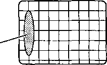
Fig. 5-7
5-6. TUNER adjustment
5-6-1. AFC adjustment
1) Set the RF output frequency of the pattern generator (PM5518) to exact 38.9 MHz (carrier only) [except UKT] or exact 38.5 MHz (carrier only) [UKT only] (IF carrier frequency) with 80 dBpV sensitivity.
2) Connect the RF output of the pattern generator to the 8 pin of the TUNER unit.
3) Connect the DC voltmeter to the resistor 9R14.
Select the menu STD-2 and a UHF band at the beginning of the bargraph with the remote control unit.
4) Adjust the 3L2 coil so that the meter indicates 3.4 ± 0.4 V.
5-6-2. AGC adjustment
1) Use the pattern generator (PM5518) to input the 60 dBpV (1mV) sensitivity RF UHF signal into the ANT.IN terminal.
2) Connect the DC voltmeter to the anodę of the 32D4.
3) Adjust VR3P1 so that the reading on the meter is 8 ± 0.5 V.
5-7. White balance adjustment
1) Set the contrast to the 1/4 position (130cd ± 10 in white signal) and brightness to the 3/4 position (2cd ± 0.2 in black signal) with the remote control unit.
2) Use the pattern generator (PM5518) to input a white signal into AV-1 (EURO socket).
3) Attach the sensor of the colour analyzer on the TV screen.
4) Adjust VR41P1 and VR41P2 on the SOCKET PCB so that the X and Y values are indicated within the following values of the coordinates of the colour temperaturo.
5) Use the pattern generator (PM5518) to input a black signal into AV-1 (EURO socket).
6) Adjust VR41P3 and VR41P4 on the SOCKET PCB so that the X and Y values are indicated within the following values of the coordinates ot the colour temperaturę.
X=0.295 ± 0.010, Y=0.303 ± 0.010 (8000 ± 1200 °K) According to CIE-xy chromaticity diagram
If results are not satisfactory, repeat adjustment from steps 5-7-4) to 5-7-6) untill correct white balance is obtained.
NOTĘ : If there is no colour analyzer available, adjust VR41P1, VR41P2, VR41P3 and VR41P4 so that the correct white picture is obtained.
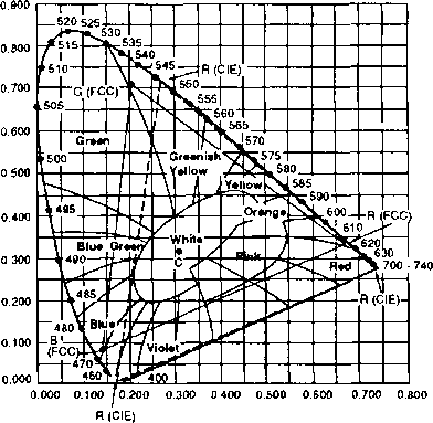
Fig. 5-8
SERYICE MANUAŁ
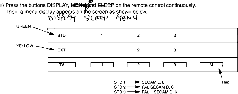
VI. FACTORY MODĘ
In the Akai factory, we choose for each model, standards and external inputs enable according to each destination. When the Main P.C. Board or EEPROM in the Main P.C. Board is replaced for any reason, memorize the content according to the following procedurę.
Choose
standards enable
EXT 1 EXT 2 EXT 3
SCART1 SCART 2
RCA in the front panel
Choose
external inputs enable
Buttons
2) Press the green button once. Then, at the same time the STD character by green colour is changed to white character.
3) Choose required STD number with 1 ~ 3 button.
4) Press the yellow button once. Then, at the same time the EXT character by yellow colour is changed to white character.
5) Choose required EXT number with 1 ~ 3 button.
6) Press the red button to memorize.
7) Press the TV button to return to normal picture.
SPECIFICATION
Description Product
|
Model |
CT |
CT |
CT |
CT |
CT |
CT |
CT |
CT |
CT |
CT | ||||||||
|
2137F |
2137UKT |
2157P |
2157E |
2157F |
2157D |
2157PT |
2157ET |
2157DT |
2157UKT | |||||||||
|
F |
U |
S |
S |
I |
G |
G |
F |
EE |
s |
S |
I |
G |
B/ |
EE |
U | |||
|
R |
K |
P |
C |
T |
E |
R |
R |
AU |
p |
C |
T |
E |
EG |
AU |
K | |||
|
A |
A |
A |
A |
R |
E |
A |
SR |
A |
A |
A |
A |
N R |
SR | |||||
|
Country |
N |
l |
NA |
L |
M |
E |
N |
TO |
I |
NA |
L |
M |
EE |
TO | ||||
|
C |
N |
DV |
I |
A |
C |
C |
P |
N |
DV |
I |
A |
L E |
P | |||||
|
E |
I I |
A |
N |
E |
E |
E |
I I |
A |
N |
UC |
E | |||||||
|
NA |
Y |
NA |
Y |
X E | ||||||||||||||
|
Classification |
E5 |
B1/B2 |
E1 |
E2 |
V2 |
V1 |
E1 |
E5 |
Y1 |
E1 |
E2 |
V2 |
V1 |
E1 |
Y1 |
B1/B2 | ||
|
1 |
Secam B/G |
o |
o |
o |
o |
o |
0 | |||||||||||
|
Reception |
2 |
Secam L/L’ |
o |
0 | ||||||||||||||
|
3 |
PAL B/G |
o |
o |
o |
o |
o |
o |
0 |
0 |
o |
o |
o |
o |
o |
o | |||
|
Standard | ||||||||||||||||||
|
4 |
PALI |
o |
o |
o |
o | |||||||||||||
|
Secam D/K |
o |
o | ||||||||||||||||
|
Input |
PAL |
o |
o |
o |
o |
o |
o |
o |
o |
o |
0 |
0 |
o |
o |
o |
o |
o | |
|
Video | ||||||||||||||||||
|
Standard |
Secam |
o |
o |
o |
o |
o |
o | |||||||||||
|
Input |
E1:Scart 1 |
o |
0 |
o |
o |
o |
o |
o |
o |
o |
o |
o |
o |
o |
o |
o |
o | |
|
E2:Scart 2 |
o |
o |
o | |||||||||||||||
|
Video | ||||||||||||||||||
|
E3:RCA |
o |
o |
o |
o |
o |
o |
o |
o |
o |
o |
o |
o |
o |
o | ||||
|
Head Phone Jack |
o |
o |
o |
o |
o |
o |
o |
o |
o |
0 |
o |
o |
o |
o |
o |
o | ||
|
Teletext |
Flof+Standard (Euro) |
o |
o |
o |
o | |||||||||||||
|
Standard (Euro) |
o |
o |
o |
o | ||||||||||||||
SERYICE MANUAŁ
9
Wyszukiwarka
Podobne podstrony:
CL2894 djvu BHMMAHME!!!3Ta cxeMa HE npeflHa3HaueHa fljiu npop;a>KM Ha ,u;MCKax.CxeMy io>k
pc 58b djvu 58B Chassis BHMMAHME!!!3Ta cxeMa HE npeffHa npeffHa3Ha»ieHa win npoffaacn Ha flncKax.Cxe
SKV2080 TXT djvu BHMMAHME!3Ta cxeMa He npe^HasHaneHa ftjiH npo^aacM js,a flMCKax.CxeMy mo>kho cbo
PC14A djvu 2.Audio Błock Diagram BHMMAHME!!!3Ta cxeMa HE npe^Ha3HaHeHa p,jin npo^aacM Ha ^MCKax.CxeM
tx92f + Service Mode djvu TX92FSchematic Diagram BHMMAHME!!!3Ta cxeMa HE npe,n;Ha3HaueHa npoftaacn H
AV 20NMG3 djvu BHMMAHME!!!3Ta cxeMa HE npe^HasHaneHa ujm npo,na>KH Ha fflHCKax.CxeMy mo^kho cboóo
4288 djvu ALIGNMENT INSIRUCTIONS BHMMAHME!!!3Ta cxeMa HE npe^Ha3HaHeHa rml npo^a^oi Ha ftMCKax.CxeMy
COLOR17DK djvu BHMMAHME!!!3xa cxeMa HE npe^HasHaneHa jpia npop;a>KM Ha ^CKax.CxeMy mo^cho cbo6o,o
SOB (3) głol-og <<- <>&■€ hjy D/HAl.ANi nK iAM/AiMl l’( i/.AK/Al " >WYf H A
DSC06877 I K< H łtf i M C / W,M 1 " Sl 1 ,r< 11DOBRE I SŁABE STRONY KONRADOWA AK Al >1
DSC06877 I K< H łtf i M C / W,M 1 " Sl 1 ,r< 11DOBRE I SŁABE STRONY KONRADOWA AK Al >1
MRTS - marginalna stopa substytucji technicznej -AK AL MRTS = Izokoszta - linie jednakowego
CCF20130324�000 R Ak ?c A. -7 AL U E - ?oooo HF* v -0.5 C^/ - 3 nov>, . ^ P;&l
slide0052 image217 Al MW t* yx * ~ ^ IsX* ®ndc» tr* 0> 9 HE & }-M*- i> O. tro/ I - C*iH &n
7028VTc25VT ch 7000LX djvu DIGI- !5ni/iMAiii/iŁi
5194 Combi djvu BHHMAHHE!!!3Ta cxena HE npeAHa3HaHeHa juw npoflajKH Ha AHCKax.Cxeny MOJKHO
więcej podobnych podstron