32419 p76

SERVI-CAR

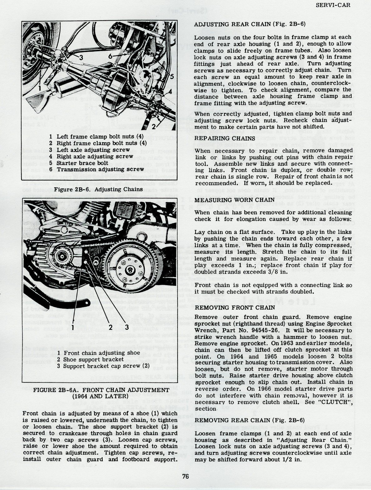
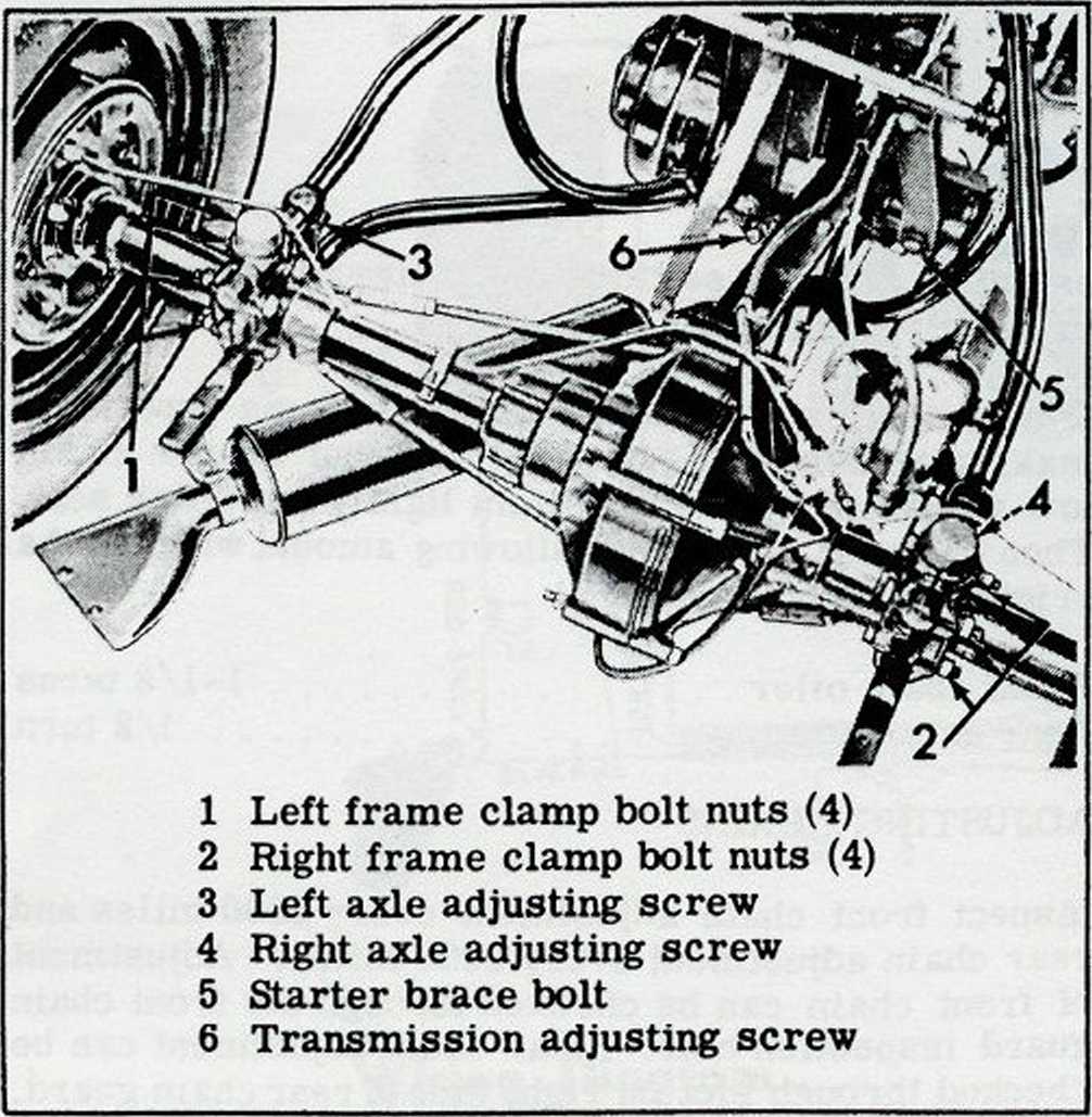
Figurę 2B-6. Adjusting Chains

1 2 3
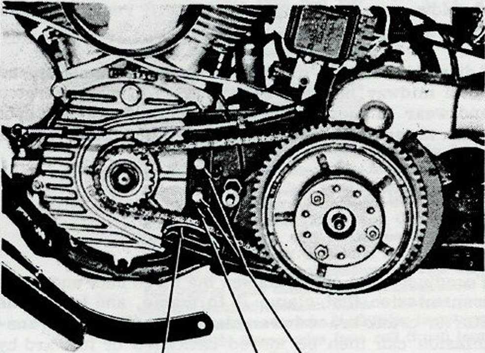
1 Front Chain adjusting shoe
2 Shoe support bracket
3 Support bracket cap screw (2)
FIGURĘ 2B-6A. FRONT CHAIN ADJUSTMENT
(1964 AND LATER)
Front chain is adjusted by means of a shoe (1) which is raised or lowered, underneath the chain, to tighten or loosen chain. The shoe support bracket (2) is secured to crankcase through holes in chain guard back by two cap screws (3). Loosen cap screws, raise or lower shoe the amount reąuired to obtain correct chain adjustment. Tighten cap screws, re-install outer chain guard and footboard support.
ADJUSTING REAR CHAIN (Fig. 2B-6)
Loosen nuts on the four bolts in frame clamp at each end of rear axle housing (1 and 2), enough to allow clamps to slide freely on frame tubes. Also loosen lock nuts on axle adjusting screws (3 and 4) in frame fittings just ahead of rear axle. Turn adjusting screws as necessary to correctly adjust chain. Turn each screw an eąual amount to keep rear axle in alignment, clockwise to loosen chain, counterclock-wise to tighten. To check alignment, compare the distance between axle housing frame clamp and frame fitting with the adjusting screw.
When correctly adjusted, tighten clamp bolt nuts and adjusting screw lock nuts. Recheck chain adjustment to make certain parts have not shifted.
REPAIRING CHAINS
When necessary to repair chain, remove damaged link or links by pushing out pins with chain repair tool. Assemble new links and secure with connect-ing links. Front chain is duplex, or double row; rear chain is single row. Repair of front chain is not recommended. If worn, it should be replaced.
MEASURING WORN CHAIN
When chain has been removed for additional cleaning check it for elongation caused by wear as follows:
Lay chain on a fiat surface. Take up playin the links by pushing the chain ends toward each other, a few links at a time. When the chain is fully compressed, measure its length. Stretch the chain to its fuli length and measure again. Replace rear chain if play exceeds 1 in.; replace front chain if play for doubled strands exceeds 3/8 in.
Front chain is not eąuipped with a connecting link so it must be checked with strands doubled.
REMOVING FRONT CHAIN
Remove outer front chain guard. Remove engine sprocket nut (righthand thread) using Engine Sprocket Wrench, Part No. 94545-26. It will be necessary to strike wrench handle with a hammer to loosen nut. Remove engine sprocket. On 1963 andearlier models, chain can then be lifted off clutch sprocket at this point. On 1964 and 1965 models loosen 2 bolts securing starter housing to transmission cover. Also loosen, but do not remove, starter motor through bolt nuts. Raise starter drive housing above clutch sprocket enough to slip chain out. Install chain in reverse order. On 1966 model starter drive parts do not interfere with chain removal, however it is necessary to remove clutch Shell. See "CLUTCH", section
REMOVING REAR CHAIN (Fig. 2B-6)
Loosen frame clamps (1 and 2) at each end of axle housing as deseribed in "Adjusting Rear Chain.'* Loosen lock nuts on axle adjusting screws (3 and 4), and turn adjusting screws counterclockwise until axle may be shifted forward about 1/2 in.
76
Wyszukiwarka
Podobne podstrony:
12422 p78 SERYI-CAR Figurę 2B-7. Servi-Car Differentiai and Axle - Exploded View 78
p79 (2) SERYI-CAR KEY FOR FIGURĘ 2B-7 1 Hydraulic brake linę assembly 2
p80 Early ModelRemoving Front Wheel (Servi-Car) Raise front end of Servi-Car by blocking-up unddrnea
- 83 - FIGURĘ 2a FIGURĘ 2b
lm Figurę 13. Adjustable Output Regulator (7V to 30V) Figurę 14. High Current Voltage Regulator Figu
p75 (2) (Seryi-Car)DRIVE CHAINS FRONT CHAIN OILER (Fig. 2B-5) At regular service intervals remove in
00225 ?49267320ac3d7851e1017e71c81bec 227 Applications of the EWMA Figurę 6. Esample of Modified Sh
00226 ?ff5d9dd7f87bcdc11138bd181d09bc 228 Baxlcy Figurę 7. Esample of Modified Shewhart Control Lar
readmylips Read My Lips A publ< figurę appeun on nationol TV and ralks his woy out of eve/ything!
> ADAMS/Car 2003.0.0 File Edit View Adjust Simulate Review Settincjs lools Hd crear nr snrin fiSW
więcej podobnych podstron