50628 Изображение29
4-20
Chapter 4 Fuel and exhaust systems


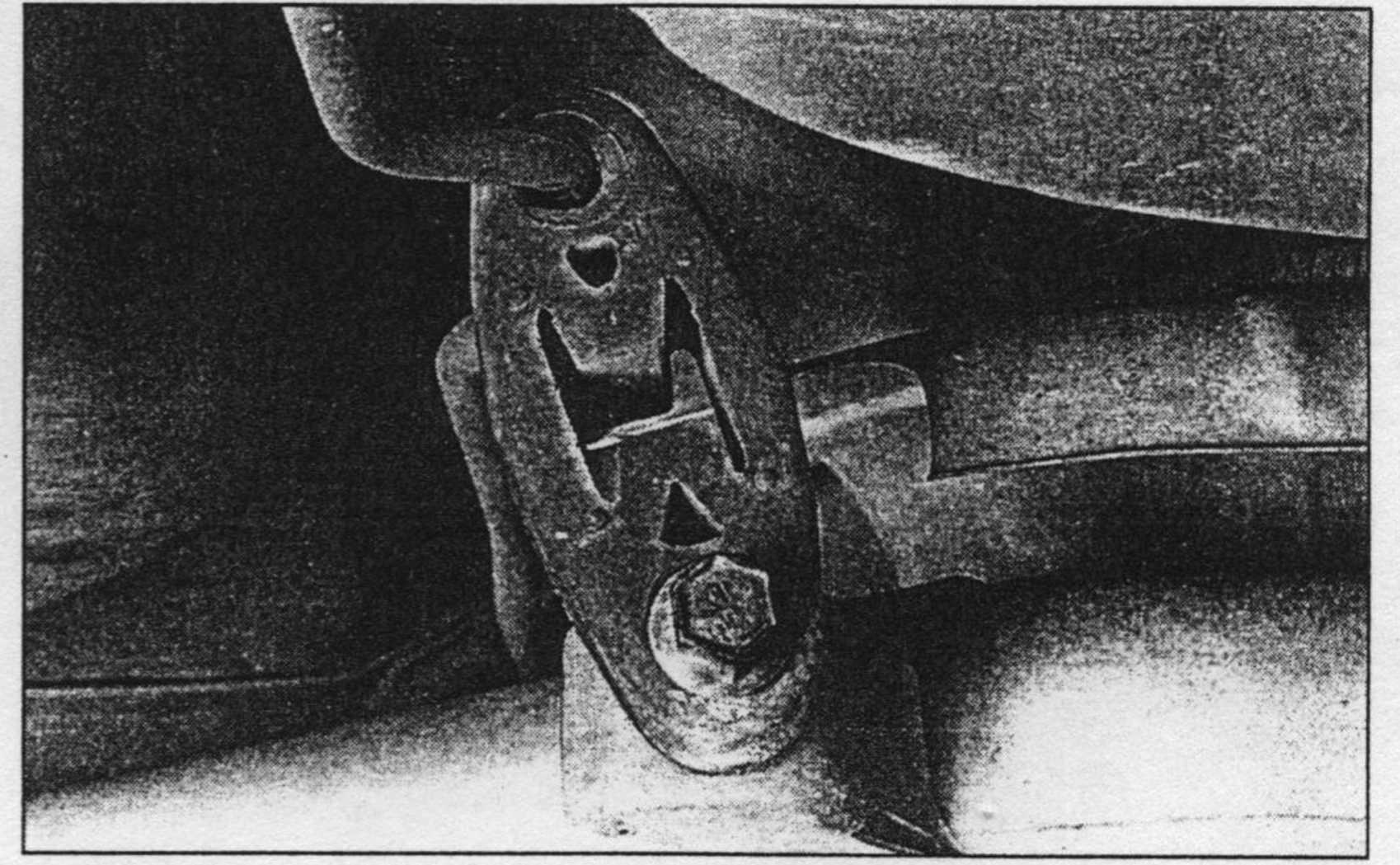
17.4 To detach this rubber błock type hanger from the
exhaust pipę, remove the bolt
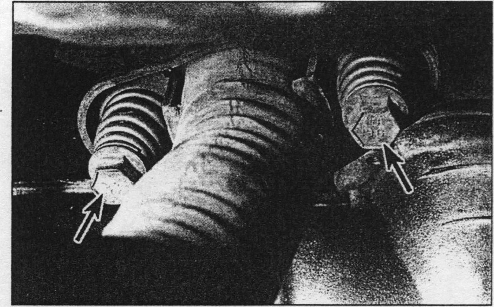
17.3 The exhaust pipę to exhaust manifold fiange boits - make surę you don’t lose the springs when removing these boits
7 Remove the oil drain hose from the tur-bocharger.
8 Remove the water return pipę.
9 Lower the vehicle.
10 Remove the coolant recovery pipę and move it to one side.
11 Remove the turbocharger induction tubę.
12 Remove the engine cooling fan (see Chapter 3).
13 Remove the oxygen sensor.
14 Disconnect the oil feed hose.
15 Remove the water feed pipę.
16 Remove the air intake duet and vacuum hose at the actuator.
17 Remove the turbocharger-to-exhaust manifold fasteners and remove the turbocharger.
18 Installation is the reverse of removal. Tighten all fasteners to the torque values listed in this Chapter’s Specifications.
17 Exhaust system components -generał information, removal and installation
Ref er to illustrations 17.3 and 17.4 Waming: The vehicle ’s exhaust system gen-erates very high temperatures and should be allowed to cool down completely before any of the components are touched. Be espe-cially careful around the catalytic converter, where the highest temperatures are gener-ated.
1 Disconnect the cable from the negative terminal of the battery. Caution: If the vehicle is eguipped with a Delco Loc II audio system, make surę you have the correct activation codę before disconnecting the battery. See the information at the front of this manuał for the radio re-activation procedurę.
2 Raise the vehicle and support it securely on jackstands.
3 Disconnect the exhaust pipę from the exhaust manifold fiange by removing the two fiange boits (see illustration).
4 Remove the bolt from the exhaust pipę rubber hanger just in front of the fuel tank (see illustration).
5 Remove the bolt and detach the hanger from the forward end of the muffler.
6 Remove the bolt and detach the hanger from the rear end of the muffler.
7 Remove the exhaust pipę, catalytic con-verter and muffler as an assembly. Notę: These components cannot be separated without cutting. If you need to replace any of these parts, take the entire assembly to a dealer or a muffler shop for further sen/ice.
Wyszukiwarka
Podobne podstrony:
Chapter 4 Fuel and lubrication systems 99 1 Always perform service procedures in a well-ventilated a
89 TransAlp Manual Fuel System 4 5 FUELSYSTEM Loosen the lock nut, and remove the fuel valve from th
65026 system 17 17 of respiration, or intestinal gases, but purely and simply of ill-smelling emanat
Abstract This study investigates the performance of a hybrid turboexpander and fuel celi (HTEFC) sys
system 17 17 of respiration, or intestinal gases, but purely and simply of ill-smelling emanations f
Zdj?cie 0047 13 14 System Park and Ride System metra na święcie iw Polsce Rozwój światowej motoryzac
Training and competence P.T.W systems are only as good as the care and competence of the people who
SCAN0122 CHAPTER 2 ▼ Cornea and Selera 27FIGURĘ 2-17 Limbus. Limbal conjunctiva (A) is formed by an
Suzuki RM125t CYLINDER, PISTON AND EXHAUST VALVE 6-1CYLINDER, PISTON AND EXHAUST VALVECONTENTS CONST
49710 n10 (4) 170 Myślenie systemowe 17 językjTTyśleniaj wygląda zupełnie inaczej dla kierownictwa,
Laptop org from PCWorld May 07 Tech lnnovations Fuel Low-Cost LaptopSTURDINESS AND SIMPLICITY ARE
więcej podobnych podstron