50634 p53

its seat as per mark madę on cable. After cables are inserted, tum seal nuts down against rubber packing washers to secure cables and to prevent water from getting inside coil.
When replacing pług cables do not heat coil to a higher degree than just warm as doing so will soften sealing compound to the extent that cable holes through compound will close up as the old cables are pulled out, blocking the insertion of new cables. In this case it is necessary to allow coil to cool and then form new cable holes by means of a piece of tubing with saw teeth filed in one end. Tubing should be of slightly larger diameter than cable. Holes through compound must be open so cables can be inserted all the way to their seats, where they con-tact high tension winding terminals; otherwise there is a gap in the high tension Circuit and coil will not function.
Servicing Ignition-Light Switch
See "Wiring Details," Page 54 for information on switch operating positions.
1. After removing instrument panel cover, dis-connecting wires and removing switch from panel, a faulty switch can be disassembled for inspection and repair as follows:
2. (All switch part positions mentioned below apply with switch up-side-down and with lock-out hutton away from you. Switch must be in "OFF" position and unlocked).
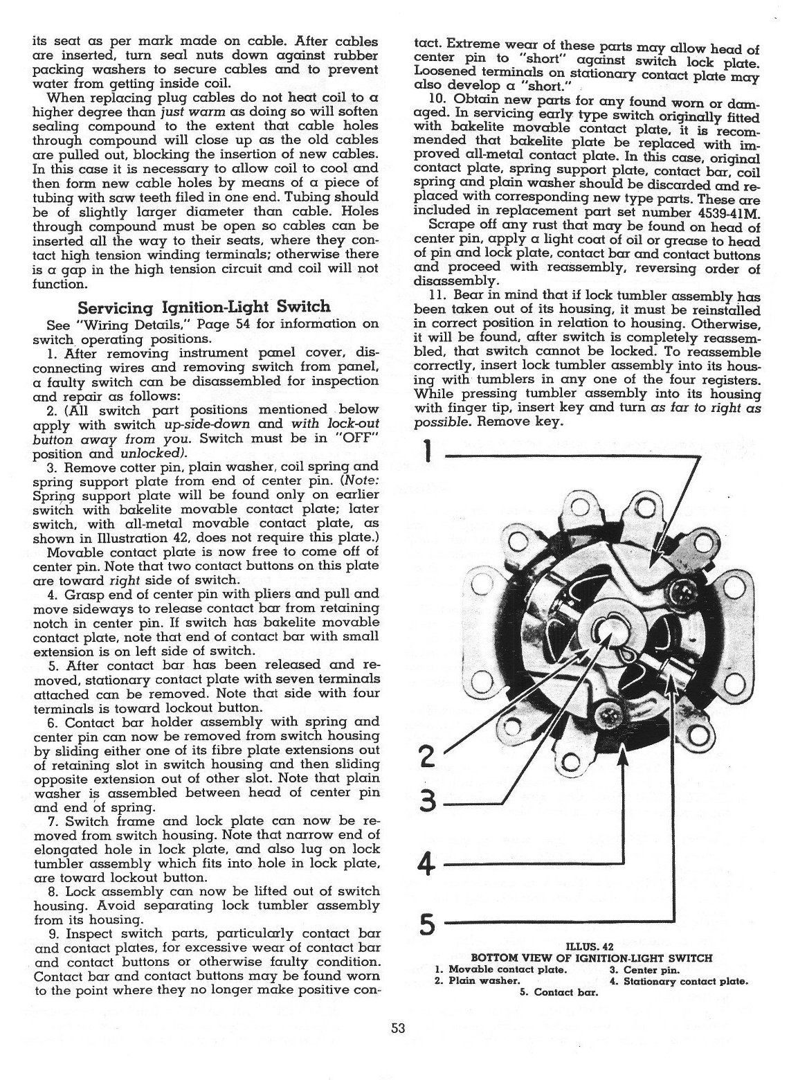
3. Remove cotter pin, plain washer, coil spring and spring support piąte from end of center pin. (Notę: Spring support piąte will be found only on earlier switch with bakelite movable contact piąte; later switch, with all-metal movable contact piąte, as shown in Illustration 42, does not reąuire this piąte.)
Movable contact piąte is now free to come off of center pin. Notę that two contact buttons on this piąte are toward right side of switch.
4. Grasp end of center pin with pliers and puli and move sideways to release contact bar from retaining notch in center pin. If switch has bakelite movable contact piąte, notę that end of contact bar with smali extension is on left side of switch.
5. After contact bar has been released and re-moved, stationary contact piąte with seven terminals attached can be removed. Notę that side with four terminals is toward lockout button.
6. Contact bar holder assembly with spring and center pin can now be removed from switch housing by sliding either one of its fibrę piąte extensions out of retaining slot in switch housing and then sliding opposite extension out of other slot. Notę that plain washer is assembled between head of center pin and end of spring.
7. Switch frame and lock piąte can now be re-moved from switch housing. Notę that narrow end of elongated hole in lock piąte, and also lug on lock tumbler assembly which fits into hole in lock piąte, are toward lockout button.
8. Lock assembly can now be lifted out of switch housing. Avoid separating lock tumbler assembly from its housing.
9. Inspect switch parts, particularly contact bar and contact plates, for excessive wear of contact bar and contact buttons or otherwise faulty condition. Contact bar and contact buttons may be found worn to the point where they no longer make positive contact. Extreme wear of these parts may allow head of center pin to "short" against switch lock piąte. Loosened terminals on stationary contact piąte may also develop a "short." .
10. Obtain new parts for any found wora or dam-aged. In servicing early type switch originally fitted with bakelite movable contact piąte, it is recom-mended that bakelite piąte be replaced with im-proved all-metal contact piąte. In this case, original contact piąte, spring support piąte, contact bar, coil spring and plain washer should be discarded and replaced with corresponding new type parts. These are included in replacement part set number 4539-4IM.
Scrape off any rust that may be found on head of center pin, apply a light coat of oil or grease to head of pin and lock piąte, contact bar and contact buttons and proceed with reassembly, reversing order of disassembly.
11. Bear in mind that if lock tumbler assembly has been taken out of its housing, it must be reinstalled in correct position in relation to housing. Otherwise, it will be found, after switch is completely reassem-bled, that switch cannot be locked. To reassemble correctly, insert lock tumbler assembly into its housing with tumblers in any one of the four registers. While pressing tumbler assembly into its housing with finger tip, insert key and turn as far to right as possible. Remove key.

3
4 -1
5 -1
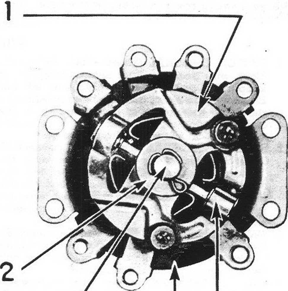
ILLUS. 42
BOTTOM VIEW OF IGNITION-LIGHT SWITCH
1. Movable contact piąte. 3. Center pin.
2. Plain washer. 4. Stationary contact piąte.
5. Contact bar.
53
Wyszukiwarka
Podobne podstrony:
a) Completely filled claiin form as per Annexure 4 b) Attested c
IMG 140228�01 E S S A Y Garrison KeillorWalking Down the Canyon AS A CHILD, I WAS MADĘ TO LOOK OUT T
The Online examinations are conducted as per the time table published by MSBTE on Ihe Website. The e
skanuj0267 OLIYIA 2 shuttles The upper part of thc wing is madę in 2 rounds. The rings b - B are tat
Sc^eeze [Uruchomiona] - Sun VirtualBo> lamed.co~lt-zones [----] i L:[ u + ii // broadcast zones a
II. War on terrorism and its rules as depicted in popular culture 5-6. Thomas Hurka. Proportionality
(magic crochet) m PATTERN STITCHES : Work in om. sm and lacet st. alternating as per diagram. Lacet
TUYNORD CERTIFICATE Management system as per PN-EN ISO 9001 : 2015 In accordance with TUV NORD Polsk
Ea»r«14 tia« ŁW« Oni ■trkin*. WCi *• Jf** We can make jewelry certificate as per customer
As Per The Revised Syllabus w.e.f. June 2018 Core Course IV HISTORY OF MEDIEVAL INDIA (1526 CE-1707
CERTIFICATE TuMNORD Management system as per EN ISO 9001 : 2008 In accordance v»«h TOV NORO CERT pro
86725 system 60 w respiration be noisy, it is a prool that the air passage is narrowed, as per examp
Tamil counterparts kojja and pottai, is “rarely used” as a derogatory term in Hindi; in fact, its em
Applications are invited from the pakistani nationals for Academic positions as per HEC approved cri
Practical Lab Manuał of Pharmaceutical Organie Chemistry -1 As Per PCI Syllabus B. Pharm 2nd Semeste
więcej podobnych podstron