73865 Page20
The Lambda sensor
The signal from the Lambda sensor is dependent on the air-fuel ratio.
The Lambda sensor measures the oxy-gen content of the exhaust gas. This oxygen content is dependent on the air-fuel mixture. The special feature of the Lambda sensor is that deviations in the air ratio /. = 1 lead to a spontaneous change in the output signal of the sensor.
The sensor consists principally of a special ceramic body, the surfaces of which are fitted with platinum elec-trodes through which gas can pass. The sensor works on the principle of the ceramic materiał, which is doped with certain metal oxides, becoming conductive at high temperatures. If the oxygen content on each side of the electrodes varies in size, then an electric voltage occurs at the electrodes. This voltage represents the measuring signal.
The sensor is arranged in the exhaust pipę from the engine in such a manner that the outer surface of the ceramic body lies in the exhaust-gas flow. The inner part, however, is in contact with theoutsideair. Thedemandsplacedon a ż-sensor are. by their very naturę, se-vere. High thermal, mechanical and even Chemical stresses occur, all of which are mastered by the sensor thanks to its clever design.
1 2

7 8
9 10
W
11
w
Li-:_—;
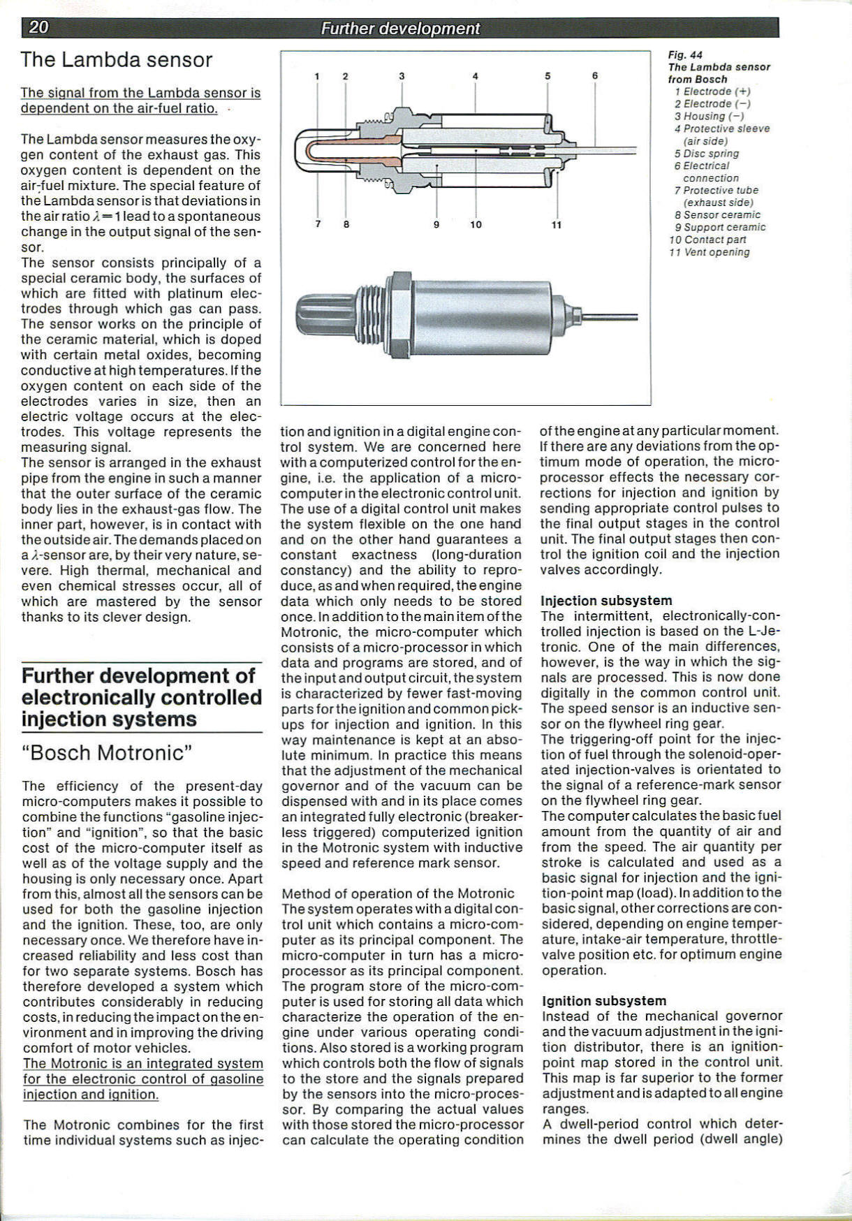
Fig. 44
The Lambda sensor from Bosch
1 Electrode (+)
2 Elecirode (-)
3 Housing (-)
4 Protective sleeve (air side)
5 Disc spring
6 Electrical connection
7 Protective tubę (exhaust side)
8 Sensor ceramic
9 Suppon ceramic
10 Contact part
11 Ventopening
Further development of electronically controlled injection systems_
“Bosch Motronic”
The efficiency of the present-day micro-computers makes it possible to combine thefunctions “gasoline injection” and “ignition”, so that the basie cost of the micro-computer itself as well as of the voltage supply and the housing is only necessary once. Apart from this, almost all the sensors can be used for both the gasoline injection and the ignition. These, too, are only necessary once. We therefore have in-creased reliability and less cost than for two separate systems. Bosch has therefore developed a system which contributes considerably in reducing costs, in reducing the impact on the en-vironment and in improving the driving comfort of motor vehicles.
The Motronic is an integrated system for the electronic control of gasoline injection and ignition.
The Motronic combines for the first time individual systems such as injec-
tion and ignition in a digital engine contro! system. We are concerned here with a computerized control for the engine, i.e. the application of a micro-computer in the electronic control unit. The use of a digital control unit makes the system flexible on the one hand and on the other hand guarantees a constant exactness (long-duration constancy) and the ability to repro-duce, as and when required, the engine data which only needs to be stored once. In addition to the main item of the Motronic, the micro-computer which consists of a micro-processor in which data and programs are stored, and of the input and output Circuit, the system is characterized by fewer fast-moving parts for the ignition and common pick-ups for injection and ignition. In this way maintenance is kept at an abso-lute minimum. In practice this means that the adjustment of the mechanical governor and of the vacuum can be dispensed with and in its place comes an integrated fully electronic (breaker-less triggered) computerized ignition in the Motronic system with inductive speed and reference mark sensor.
Method of operation of the Motronic The system operates with a digital control unit which contains a micro-computer as its principal component. The micro-computer in turn has a micro-processor as its principal component. The program storę of the micro-computer is used for storing all data which characterize the operation of the engine under various operating condi-tions. Also stored is a working program which Controls both the flow of signals to the storę and the signals prepared by the sensors into the micro-processor. By comparing the actual va!ues with those stored the micro-processor can calculate the operating condition
of the engine atany particuiar moment. If there are any deviations from the optimum modę of operation, the micro-processor effects the necessary cor-rections for injection and ignition by sending appropriate control pulses to the finał output stages in the control unit. The finał output stages then control the ignition coil and the injection valves accordingly.
Injection subsystem
The intermittent, eiectronically-con-trolled injection is based on the L-Je-tronic. One of the main differences, however, is the way in which the signals are processed. This is now done digitally in the common control unit. The speed sensor is an inductive sensor on the flywheel ring gear.
The triggering-off point for the injection of fuel through the solenoid-oper-ated injection-valves is orientated to the signal of a reference-mark sensor on the flywheel ring gear.
The Computer calculates the basie fuel amount from the quantity of air and from the speed. The air quantity per stroke is calculated and used as a basie signal for injection and the igni-tion-point map (load). In addition to the basie signal, other corrections are con-sidered, depending on engine temperaturę, intake-air temperaturę, throttle-valve position etc. for optimum engine operation.
Ignition subsystem
Instead of the mechanical governor and the vacuum adjustment in the ignition distributor, there is an ignition-point map stored in the control unit. This map is far superior to the former adjustment and is adapted to all engine ranges.
A dwell-period control which deter-mines the dwell period (dwell angle)
Wyszukiwarka
Podobne podstrony:
007 6 Sailbaot Connect the dots from A to P. Color. Sara is sailing on a sunny day. O Pmr.ie Schaler
Suzuki RM125G MACHINĘ TUNING 4-3 As shown below, each tuning part is located between the air/fuel pa
DSC07452 cUMMARY FROM „HINTERLAND" TO „INNOLAND" - THAT IS HOW TO DEYELOP THE RURAL AREAS
81764 Page21 Further deyelopment21 dependent on the speed and supply voltage, adapts the ignition en
GROWTł I. NODE DEYELOPM ENT AND ESTIMATED Y1ELD OF (Al A MUS MANAN increase instem length. On the lo
image001 SJL3ira0l)NlAlŁjaililiN30! The only book about FlYłNG SAUCERS based enłirely on OFFICIAL AI
image002 The only book obouł FlYtłiG SAUCERS based entirely on OFFiCIAL AIR FORCF REĆOROS
00233 ?994b263585678f9e7929f08dc27281 235 Applications of the EWMA Closed-loop sigma (ar) is calcul
00435 ?638d50a938c7a2f85d18a38dd8caa3 440Russell c) the iterates exhibit sensitive dependence on in
SNC00523 32 Thermography m human medicine Thermography or thermovision jn medfcme is based on the na
więcej podobnych podstron