Suzuki RM125G
MACHINĘ TUNING 4-3
As shown below, each tuning part is located between the air/fuel passage and has its own air/fuel mixture adjustable rangę in terms ot the throttle valve opening. The chart indicates that the carburetor can supply correct air/fuel mixture to the engine in any rangę because of the overlapping adjustable rangę of the each part.
|
TUNING PARTS |
THROTTLE VALVE OPENING | |||
|
MAIN JET | ||||
|
JET NEEDLE CLIP POSITION |
<T a |
D | ||
|
JET NEEDLE O.D. | ||||
|
PILOT JET AND AIR SCREW | ||||
|
THROTTEL OPENING |
1/ |
4 1 _J |
f2 ... 3 _ |
'4 _ |
© MAIN SYSTEM ® INTERMEDIATE SYSTEM @ PILOT SYSTEtój>
AIRSCREW
i *

X /
<r
V
V
V \

When performing carburetor tuning, first find out in. what throttle opening rangę an improper air/fuel \ mixture is supplied, by checking the . cobr of\ exhaust smoke, spark pług, throttle ręspbiise/ power, etc. Second, replace orradjust thepart(ś), related to the throttle opening rapgę by referring to
./f ^ ii
the following instructipńs. The siżeś refejred to in
• i .*■
the illustrations are those óf. standard setting.
PILOT JET
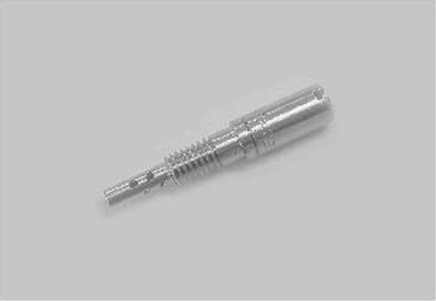
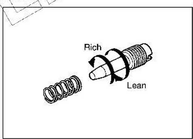
The air screw is located in the inlet air passage and meters the air for the slow system. As it has a right-hand thread, tightening it makes the passage narrower, allowing less amount of intake air to flow and resulting in richer air/fuel mixture. Air flow adjustment is effective within a rangę of 1/2-2 turns out.
The pilot jet meters the fuel supplied to the pilot system. Each jet size is indicated by a number. Larger number means a larger borę diameter and fitting a larger numbered pilot jet enriches the air/fuel mix-ture.
Wyszukiwarka
Podobne podstrony:
42791 Suzuki RM250? 94 FUEL SYSTEM As shown below, each of the asterisk (*) marked parts is located
Suzuki RM125F 4-2 MACHINĘ TUNINGCARBURETOR TUNING The carburetion of your motorcycle was carefully s
Suzuki RM125T 4-10 MACHINĘ TUNINGOIL OUANTITY MINOR ADJUSTMENT ADDING THE FORK OIL • &nb
47618 Suzuki RM125R 4-8 MACHINĘ TUNING 4-8 MACHINĘ TUNING Lean Rich Ex. Pilot jet #42.5
74863 Suzuki RM125E MACHINĘ TUNING 4-1MACHINĘ TUNINGCONTENTS CARBURETOR
86082 Suzuki RM125W MACHINĘ TUNING 4-13 MACHINĘ TUNING 4-13 v- DS5HSPRING CHANGE *
Suzuki RM125I MACHINĘ TUNING 4-5THROTTLE STOP SCREW The throttle stop screw determines the fuli clos
Suzuki RM125P 4-6 MACHINĘ TUNINGCARBURETOR TUNING IN PRACTICE In the previous section. basie princip
Suzuki RM125S MACHINĘ TUNING 4-9FRONT FORK TUNING The front fork compression and rebound damping for
Suzuki RM125U MACHINĘ TUNING 4-11OIL CHANGE (Only for outer tubę oil cham-ber) • R
36970 Suzuki RM125a MACHINĘ TUNING 4-17 MACHINĘ TUNING 4-17 D2S3SPRING PRE-LOAD ADJUSTMENT • &
więcej podobnych podstron