9

HOW TO USE THIS MANUAŁ
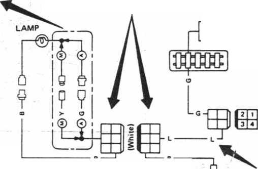
10. Symbols used in WIRING DIAGRAM are shown below. "Example"
BRANCH
M/T model
A/T model
|
— | |
|
CONNECTOR | |
|
This shows that these connectors are white 6 terminal pin-type connectors. | |
|
_ Pin-type connector (Małe) | |
|
Ug Pin-type connector ™ (Female) | |
|
rm Plain-type connector “ (Małe) | |
|
rm Plain-type connector ™ (Female) | |
POWER
• This shows the igni-tion switch position in which the system can be operated.
• For details, refer to POWER SUPPLY.
@ : M/T model @ : A/T model
t
ABBREYIATIONS
IGNITION SWITCH ACCorON
FUSE
BŁOCK
@> • j (łD body
V GROUND

|
OM |
OM | |
|
1 | ||
|
2 |
T | |
|
3 |
O | |
|
4 |
SWITCH
SWITCH
This shows that conti-nuity exists between terminals (]) and S), when the switch is turned to ON position.
LOCATION NUM8ER This number is identical with the one of the HARNESS LAYOUT. This shows where the connector is located. I
©

Main harness
Instrument
harness
WIRE COLOR CODING
|
B |
- Black |
BR |
* Brown |
|
W |
* White |
OR |
* 0rangę |
|
R |
- Red |
P |
» Pink |
|
G |
■ Green |
PU |
■ Purple |
|
L |
■ Blue |
GY |
* Gray |
|
Y |
” Yellow |
SB |
■ Sky blue |
|
LG |
• Light Green |
In case of color coding using a Stripe. Base Color is given first, followed by the Stripe Color:
Example: L/W - Blue with White Stripa
SEL984C
11. TROUBLE DIAGNOSES AND CORRECTIONS are included in sections dealing with complicated units.
12. SERVICE DATA AND SPECIFICATIONS and a list of SPECIAL SERVICE TOOLS are contained at the end of each section for quick reference of data and special tools.
13. The captions WARNING and CAUTION warn you of steps that must be followed to prevent personal injury and/or damage to some part of the vehicle.

Wyszukiwarka
Podobne podstrony:
Suzuki RM250 4 HOW TO USE THIS MANUAŁTO LOCATE WHAT YOU ARE LOOKING FOR: 1. The te
HOW TO USE THIS MANUAŁ 1. A Ql)ICK REFERENCE INDEX, a black tab
89 TransAlp Manual How To Use 1 0 HOW TO USE THIS MANUAŁ Follow the Maintenance Schedule (Section 3)
HOW TO USE THIS MANUAŁ "Example" 7. THE FOLLOWING SMALL ILLUSTRATION shows the important s
Suzuki RM250 4 HOW TO USE THIS MANUAŁTO LOCATE WHAT YOU ARE LOOKING FOR: 1. The te
34581 img025 4°C,3cl° p C o cioc; ci° ci cJ° c:z 0 ( How To Use This Manuał This book is primarily a
How to use ?Walnut has two joints. In this method, using the soft side of the walnut is very easy to
let s cut paper00 How to use this book ’Keła mul rnjov.f Kumon’s First Steps Workbooks are designed
Spis treści Wstęp........................................................ A glimpse on how to use th
How to use this bookI Rolo* and eii)ovf Kumon s First Steps Workbooks are designed so that children
How to use this book B Iłem (o ciił with .scissors Show your child how to cut along the designated l
ELECTRICAL SYSTEMSECTION When you read wiring diagrams: • Read Gl section, "HOW TO USE THIS
Actions 2 actions in Photoshop. This tutorial will teach you how to use actions in Photoshop CS. An
więcej podobnych podstron