3582278881
POWER ELECTRONICS LAB. EED
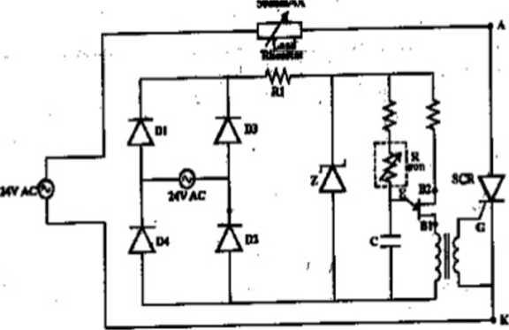
Circuit Diagram :
s
Procedurę:
1. Connect the input supply to the trainer module
2. Connect one end of the load rheostat to A of the SCR
3. Connect the otlier end of the load rheostat to P terminal of 24V AC supply
4. Connect G| &. K] terminals of UJT firing Circuit to G & K of SCR
5. Switch ON tlte supply. Power ON/OFF switch. 24V ac Switch. Supply to CRO
6. Observe the waveform for input AC voltage &. PuLsating DC voltage
7. Obsenre the Zener diodę vohage( T4) & capacitor vohage (T5)
8. Plot tli e wa ve form s
9. Repeat the e.\periment for various firing angles Ohservation Tahle:
|
Vrms |
T(mscc) |
t (msec) |
(l (degrees) |
Votmea.su red) |
Vo(cal) Vm =-(l+cosa) V 2n_ . |
|
25.8 |
3.2 |
0.4 |
O 10.78 |
10.99 |
11.5 |
19
Wyszukiwarka
Podobne podstrony:
POWER ELECTRONICS LAB. EED Transfer Characteristics: 15) Keep the V o: constant us
POWER ELECTRONICS LAB. EED 8) Connect a voltmeter across the gate -emitter and another voltmeter acr
POWER ELECTRONICS LAB. EED 4. Draw the equivalent Circuit of IGBT. 5. What arc on
POWER ELECTRONICS LAB. EED Ołuscry ation Ta Mc: I«; =--------- mA Iu (mA) Vak l
Jvc av25vm1en,av28vm1en,ja chassis djvu AV-25VM1 EN AV-28VM1EN CRT SOCKET PWB CIRCUIT DIAGRAM_ Refer
CIRCUIT DIAGRAM SYMBOLS electrical netwcrk ełemerts three-phase ine or cable single-phase Ihe or
ch TPM5 1E LA Power 42" & 47" mt PowerLIPS-1 Circuit Diagrams and PWB Layouts TPM5.1E
(YMYA)600W AUDIO AMP Amplifier Circuit diagram Power supply Circuit diagram Audio amp You can use on
76919 skan8 (6) 1 CONTROL CIRCUIT DIAGRAM C5001 0.0047/250 IARD (TN-A) TUNER IF CONNECTION CIRCUIT D
Electronic Lab ManuałBCA I SEMESTERSubject Codę: BCA-104P ELECTRONICS LABORATORY MANUAŁ Digital circ
2? If you want lo connect an electret microphone to the FM oscilator connect the ♦ of the power supp
00041 ?5182e98865725a7daf6c31d7124360 40 Molnau PROGRAM CONTROL DIAGRAM PROCEDURĘ
POWER ELECTRONICS * Power Electronics Espofia S.L. Leonardo da Vinci 24-26 46980 PA
Circuit Diagrams:- RADIAL FEEDER Fig 3.3 Loop Feeder A I,C
Note.Resistors watt onless marked. CapadtowMTD dcnotcd by decimals, MMFD by wbole numbers. Circuit d
WP 150309�1 Lab No 3. Tablicy -1) Napisz procedurę (patrz niżej) która w pętli generuje jednowymiaro
więcej podobnych podstron