1310109087
Projektowanie procesów technologicznych wytloczek ... 53
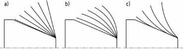
Rys. 5. Rodzaje trajektorii ruchów narzędzia podczas wyoblania: a) liniowa b) łukowo wypukła c) łukowo wklęsła Fig. 5. Kinds of tool trajectories in spinning: a) linear, b) convex arc, c) concave arc
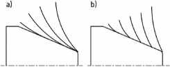
Rys. 6. Rozkład kolejnych ruchów rolki podczas procesu wyoblania: a) stopniowe zmniejszanie średnicy krążka, b) stopniowe kształtowanie na wzorniku
Fig. 6. Roller motions during the spinning process: a) gradual reduction ofthe disk diameter, b) gradual forming on the mandrel
Wybór rodzaju kolejnych ruchów narzędzia jest uzależniony przede wszystkim od kształtu oraz od długości wytłoczki. Dla długich wyrobów korzystne jest stosowanie ruchów ze stopniowym odkształcaniem materiału na wzorniku (rys. 6b). Natomiast dla przedmiotów krótkich korzystniej jest stosować ruchy o stałym zmniejszaniu średnicy krążka (rys. 6a). Podyktowane jest to uzyskaniem większej równomierności rozkładu grubości ścianki oraz krótszym czasem trwania procesu kształtowania.
Narzędzie kształtujące - rolka pracuje zarówno podczas ruchu w kierunku brzegu krążka jak i odwrotnym (rys. 7). Kierunek poruszania się rolki wpływa na rodzaj wprowadzanych naprężeń do materiału. Rolka poruszając się ku brzegowi krążka pocienia go na mniejszych średnicach a pogrubia na większych. W przypadku ruchu w przeciwnym kierunku sytuacja jest odwrotna. Należy pamiętać, że podczas ruchu rolki w kierunku dociskacza materiał zbiera się przed rolką i konieczne jest rozprowadzenie tego materiału. Nierozprowadzenie tego materiału może spowodować powstanie zgrubień materiału na części wyrobu dociśniętej już do wzornika.
The selection of the tool motion kind is related, first of all, to the drawpiece shape and length. For long products, it disadvanta-geous to apply motions with gradual materiał deformation of the mandrel (fig. 6b). For short objects, on the other hand, it is better to apply motions with smali reduction ofthe disk diameter (fig. 6a). This is to obtain a morę even distribution of the wali thickness and shorter forming process time.
The forming, i.e. the roller, works both during its movement towards the disk edge and in the opposite direction (fig. 7). The roller movement direction influences the kind of stresses introduced into the materiał. The roller, moving towards the disk edge, thins it on the smaller diameters and makes it thicker on the longer ones. In the case of the other roller movement direction, the situation is opposite. It should be kept in mind that, during the roller movement toward the blankholder, the materiał gathers in front of the roller and it has to be distributed. If it is not distributed, shoulders of materiał can arise on the product part already pressed to the mandrel.
Wyszukiwarka
Podobne podstrony:
Projektowanie procesów technologicznych wytloczek ... 55 Rys. 10. Rozkład grubości ścianki osłony
Projektowanie procesów technologicznych wytioczek ... 51 Rys. 4. Rodzaje wad podczas wyoblania: a)
Projektowanie procesów technologicznych wytloczek ... 473. SCHEMAT PROCESU WYOBLANIA Na rys. 2 przed
Projektowanie procesów technologicznych wytloczek ... 49 Stosowanie większego promienia rolki popraw
M Feld TBM392 392 9. Projektowanie procesu technologicznego części klasy tuleja i tarcza TABLICA 9.1
M Feld TBM320 320 8. Projektowanie procesu technologicznego części klasy wał RYS. 8.90. Rodzaje noży
M Feld TBM031 31 1.4. Dane wejściowe do projektowania procesu technologicznego TABLICA 1.3. Wpływ ro
M Feld TBM033 33 1.4. Dane wejściowe do projektowania procesu technologicznego RYS. 1.13. Szkic do o
M Feld TBM268 268 8. Projektowanie procesu technologicznego części kiasy wał RYS. 8.13. Kolejność pl
więcej podobnych podstron