8342936734

2. PERMANENT MAGNET BRUSHLESS MOTOR (BLDC)
A typical topology of a conventional DC brush motor with stator PM (or electromagnetic) excitation and a rotor comprising the armaturę winding and the mechanical commutator with brushes is shown in Fig.2.1a. The mechanical commutator is in fact an electromechanical DC - AC bi-directional power flow power converter as the currents in the rotor armaturę coils are AC while the brush current is DC. Brushes make mechanical contact with a set of electrical contacts on the rotor (called the commutator), forming an electrical Circuit between the DC electrical source and the armaturę coil-windings. As the armaturę rotates on axis, the stationary brushes come into contact with different sections of the rotating commutator. The commutator and brush system form a set of electrical switches, each firing in seąuence, such that electrical-power always flows through the armaturę coil closest to the stationary stator pole (permanent magnet or electrically excited).
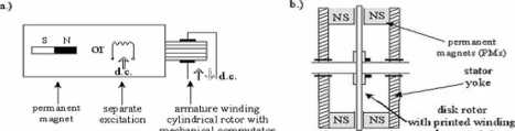
Fig.2.1. a) ConventionaI DC brush motor with cylindrical rotor, b) PM DC motor with disk rotor.
mechanical commulalor
and commntator
Fig.2.1b shows an axial air gap PM DC brush motor with a printed - winding ironless -disk rotor and the mechanical commutator with brushes. PM excitation, especially with the nonmagnetic disk rotor, yields extremely Iow electric time constants L/R (around or less than 1 ms in the sub kW power rangę). Thus ąuick response in current (torąue) is expected, though the current (torąue) harmonics are large unless the switching freąuency in the PEC is not high enough.
Unfortunately the mechanical commutator though not bad in terms of losses and power density has serious commutation current and speed limits and thus limits the power per unit to 1 - 2 MW at 1000 rpm and may not be at all accepted in chemically aggressive or explosion -prone environments.
In a BLDC motor, the electromagnets do not move; instead, the permanent magnets rotate and the armaturę remains static (Fig.2.2). This gets around the problem of how to transfer current to a moving armaturę. In order to do this, the brush-system/commutator assembly is replaced by an intelligent electronic controller. The controller performs the same power distribution found in a brushed DC motor, but using a solid-state Circuit rather than a commutator/brush system.
BLDC motors offer several advantages over brushed DC motors, including higher reliability, reduced noise, longer lifetime (no brush erosion), elimination of ionizing sparks

UNIA EUROPEJSKA
EUROPEJSKI FUNDUSZ SPOŁECZNY
m
Materiały dydaktyczne dystrybuowane bezpłatnie.
Projekt współfinansowany ze środków Unii Europejskiej w ramach Europejskiego Funduszu Społecznego
18
Wyszukiwarka
Podobne podstrony:
PROGRAM ROZWOJOWY ^1 POLITECHNIKI WARSZAWSKIEJPROGRAM ROZWOJOWY 2. PERMANENT MAGNET BRUSHLESS MOTOR
program rozwojowy Ćwiczenie 51 politechniki warszawskiej „Czujniki pól magnetyczn
PROGRAM ROZWOJOWY^1 POLITECHNIKI WARSZAWSKIEJ Only for the linear case (no magnetic saturation) the
PROGRAM ROZWOJOWY^1 POLITECHNIKI WARSZAWSKIEJ The symmetry of magnetic Circuit leads to the almost z
PROGRAM ROZWOJOWY^1 POLITECHNIKI WARSZAWSKIEJ Only for the linear case (no magnetic saturation) the
PROGRAM ROZWOJOWY^1 POLITECHNIKI WARSZAWSKIEJ The symmetry of magnetic Circuit leads to the almost z
PROGRAM ROZWOJOWY POLITECHNIKI WARSZAWSKIEJ Ćwiczenie 11 „Czujniki pól magnetycznych. Badanie
PROGRAM ROZWOJOWY lUl POLITECHNIKI WARSZAWSKIEJ Ćwiczenie 3 „Czujniki pól magnetycznych. Badanie
PROGRAM ROZWOJOWY POLITECHNIKI WARSZAWSKIEJ Ćwiczenie 7 „Czujniki pól magnetycznych. Badanie
PROGRAM ROZWOJOWY POLITECHNIKI WARSZAWSKIEJ Ćwiczenie 9 „Czujniki pól magnetycznych. Badanie
PROGRAM ROZWOJOWY ^1 POLITECHNIKI WARSZAWSKIEJ dr inż. Adam BiernatElectrical Machines in the Power
PROGRAM ROZWOJOWY^1 POLITECHNIKI WARSZAWSKIEJ phase conducts), and maximum torąue is achieved by max
PROGRAM ROZWOJOWY^1 POLITECHNIKI WARSZAWSKIEJ a = Ua — The maximum value of #w, for Qon = 0 (zero ad
PROGRAM ROZWOJOWY^1 POLITECHNIKI WARSZAWSKIEJ It should be noticed that the interval of conduction i
PROGRAM ROZWOJOWY^1 POLITECHNIKI WARSZAWSKIEJ By adjusting the turn-on and turn-off angles so that t
PROGRAM ROZWOJOWY^1 POLITECHNIKI WARSZAWSKIEJ To solve above eąuation one must find transient curren
PROGRAM ROZWOJOWY^1 POLITECHNIKI WARSZAWSKIEJ Fig. 1.15. Instantaneous value of voltage and current
PROGRAM ROZWOJOWY^1 POLITECHNIKI WARSZAWSKIEJ Fig. 1.17. a) One key switch. b) Unipolar current
PROGRAM ROZWOJOWYPOLITECHNIKI WARSZAWSKIEJPERMANENT MAGNET AND SWITCHED RELUCTANCE
więcej podobnych podstron